SUZUKI GRAND VITARA 1987 Service Repair Manual
Manufacturer: SUZUKI, Model Year: 1987, Model line: GRAND VITARA, Model: SUZUKI GRAND VITARA 1987Pages: 962, PDF Size: 27.87 MB
Page 381 of 962
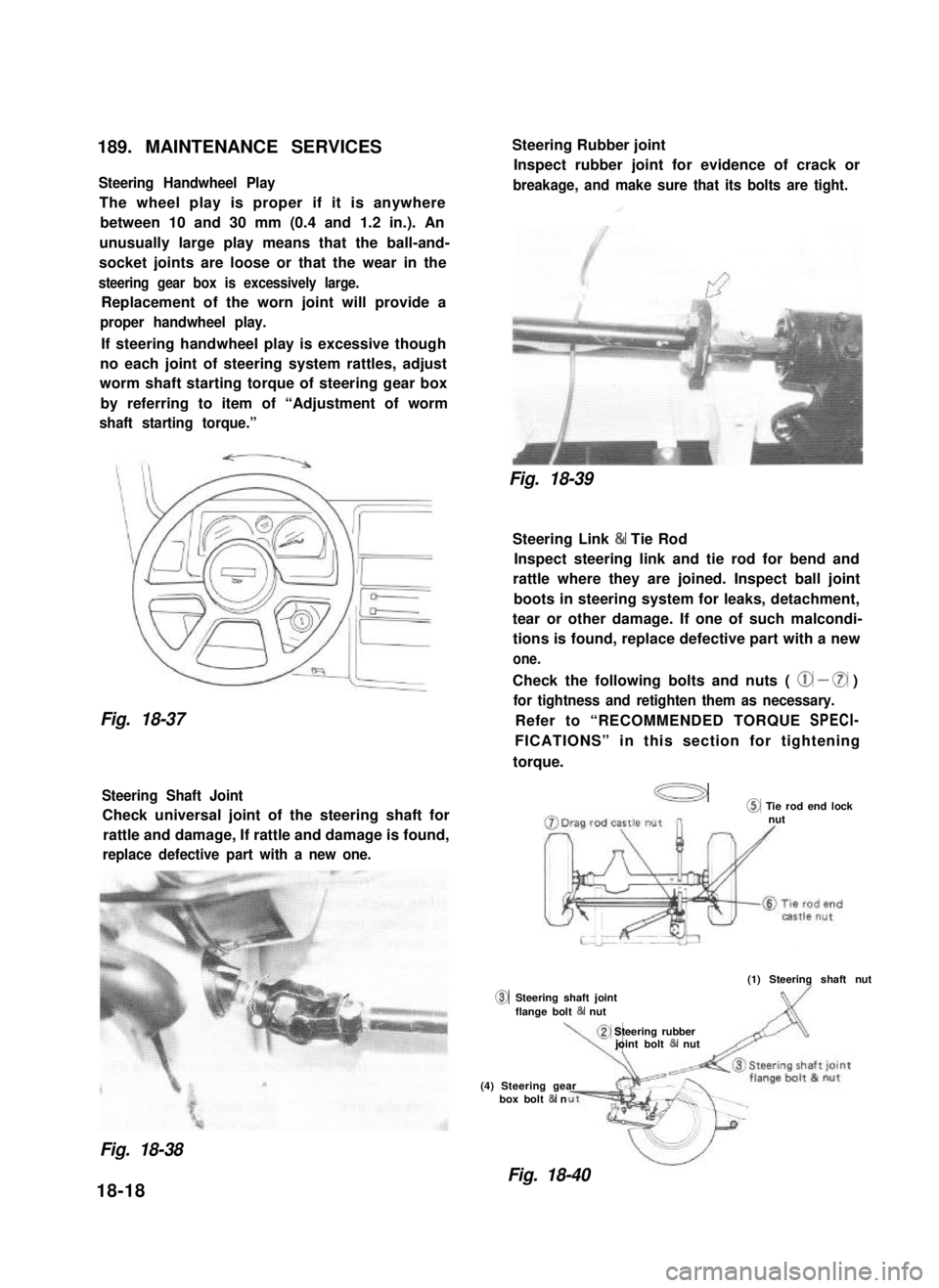
189. MAINTENANCE SERVICES
Steering Handwheel Play
The wheel play is proper if it is anywhere
between 10 and 30 mm (0.4 and 1.2 in.). An
unusually large play means that the ball-and-
socket joints are loose or that the wear in the
steering gear box is excessively large.
Replacement of the worn joint will provide a
proper handwheel play.
If steering handwheel play is excessive though
no each joint of steering system rattles, adjust
worm shaft starting torque of steering gear box
by referring to item of “Adjustment of worm
shaft starting torque.”
Fig. 18-37
Steering Shaft Joint
Check universal joint of the steering shaft for
rattle and damage, If rattle and damage is found,
replace defective part with a new one.
0
Steering Rubber joint
Inspect rubber joint for evidence of crack or
breakage, and make sure that its bolts are tight.
Fig. 18-39
Steering Link & Tie Rod
Inspect steering link and tie rod for bend and
rattle where they are joined. Inspect ball joint
boots in steering system for leaks, detachment,
tear or other damage. If one of such malcondi-
tions is found, replace defective part with a new
one.
Check the following bolts and nuts ( @ - 0 )
for tightness and retighten them as necessary.
Refer to “RECOMMENDED TORQUE SPECI-
FICATIONS” in this section for tightening
torque.
a@ Tie rod end locknut
(1) Steering shaft nut
Steering shaft jointflange bolt 84 nut
\,
@ Steering rubberjoint bolt & nut
(4) Steering gearbox bolt & n
Fig. 18-38
Fig. 18-40
18-18
Page 382 of 962
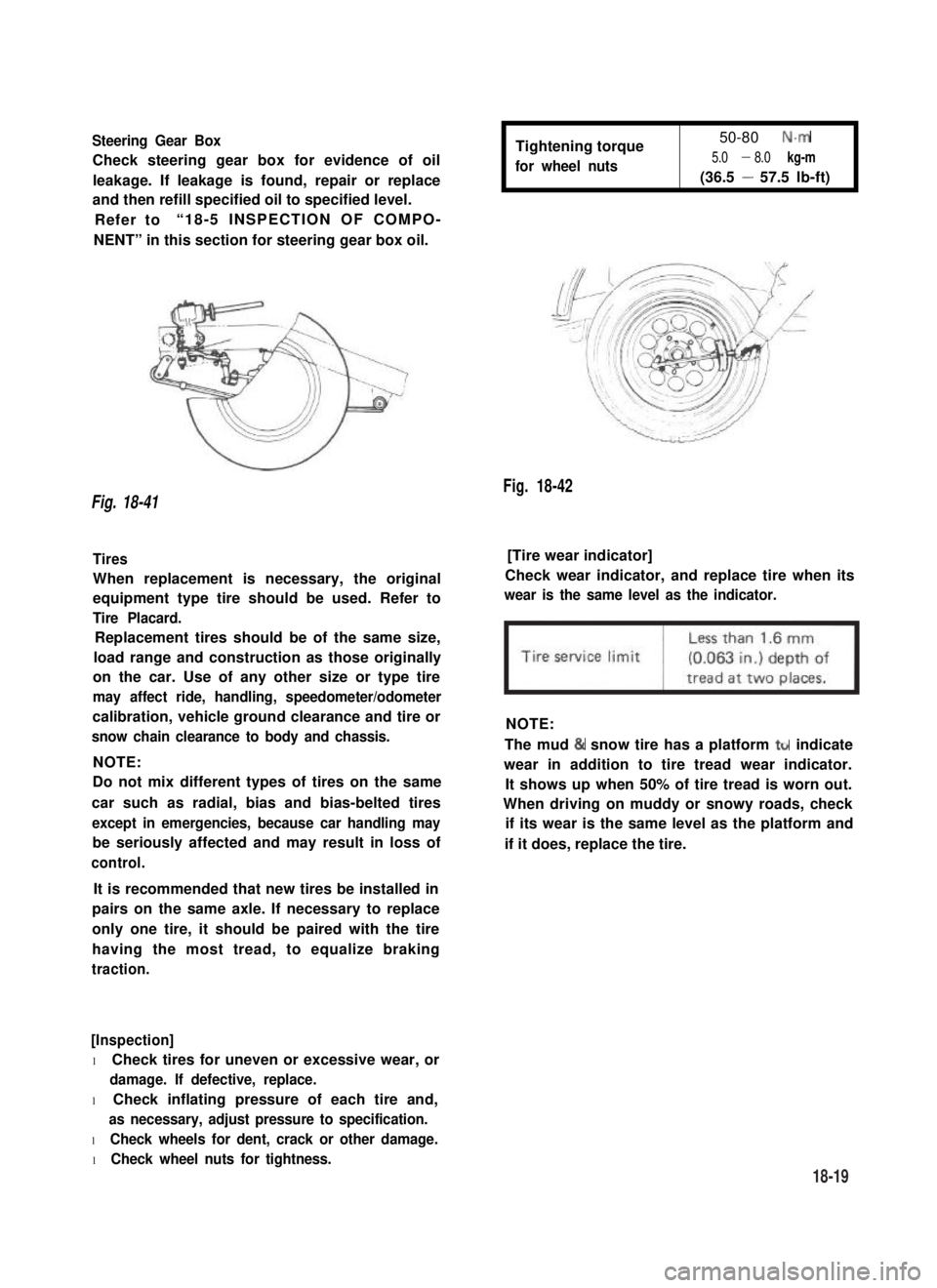
Steering Gear Box
Check steering gear box for evidence of oil
leakage. If leakage is found, repair or replace
and then refill specified oil to specified level.
Refer to“18-5 INSPECTION OF COMPO-
NENT” in this section for steering gear box oil.
Tightening torque
for wheel nuts
50-80 N.m
5.0 - 8.0 kg-m
(36.5 - 57.5 lb-ft)
Fig. 18-42
Fig. 18-41
Tires[Tire wear indicator]
When replacement is necessary, the original
equipment type tire should be used. Refer to
Tire Placard.
Check wear indicator, and replace tire when its
wear is the same level as the indicator.
Replacement tires should be of the same size,
load range and construction as those originally
on the car. Use of any other size or type tire
may affect ride, handling, speedometer/odometer
calibration, vehicle ground clearance and tire or
snow chain clearance to body and chassis.
NOTE:
NOTE:
Do not mix different types of tires on the same
car such as radial, bias and bias-belted tires
except in emergencies, because car handling may
be seriously affected and may result in loss of
control.
The mud & snow tire has a platform ttr indicate
wear in addition to tire tread wear indicator.
It shows up when 50% of tire tread is worn out.
When driving on muddy or snowy roads, check
if its wear is the same level as the platform and
if it does, replace the tire.
It is recommended that new tires be installed in
pairs on the same axle. If necessary to replace
only one tire, it should be paired with the tire
having the most tread, to equalize braking
traction.
[Inspection]
l Check tires for uneven or excessive wear, or
damage. If defective, replace.
l Check inflating pressure of each tire and,
as necessary, adjust pressure to specification.
l Check wheels for dent, crack or other damage.
l Check wheel nuts for tightness.
18-19
Page 383 of 962
![SUZUKI GRAND VITARA 1987 Service Repair Manual Fig. 18-43 @ Tire tread wear indicator
@ Wear indicating platform
[ Inflation of tires]
l Tire inflation pressures are listed on the
Tire Placard at driver’s side of instrument
panel.
l Tire inflati SUZUKI GRAND VITARA 1987 Service Repair Manual Fig. 18-43 @ Tire tread wear indicator
@ Wear indicating platform
[ Inflation of tires]
l Tire inflation pressures are listed on the
Tire Placard at driver’s side of instrument
panel.
l Tire inflati](/img/20/57437/w960_57437-382.png)
Fig. 18-43 @ Tire tread wear indicator
@ Wear indicating platform
[ Inflation of tires]
l Tire inflation pressures are listed on the
Tire Placard at driver’s side of instrument
panel.
l Tire inflation pressures should be checked
(including spare tire) at least monthly and
when significantly changing the load in the
car.
l Always check tire inflation pressures when
tires are “cold”.
l Always use tire pressure gauge when checking
inflation pressure.
l Be sure to reinstall tire inflation valve caps to
prevent dirt and moisture from getting into
valve core, as they may cause air leakage.
l If air loss occurs while driving, do not drive
on the deflated tire more than is needed to
stop safety. Driving even a short distance on a
deflated tire can damage a tire and wheel
beyond repair.
NOTE:
Before installing wheels, remove any build-up of
corrosion on the wheel mounting surface and
brake drum or disc mounting surface by scraping
and wire brushing. Installing wheels without
good metal-to-metal contact at the mounting
surfaces can cause wheel nuts to loosen, which
can later allow a wheel to come off while the
car is moving.
RADIAL TIRES
.i II
9T
\
I
4-wheels
Fig. 18-44
fT
u
[I
5-wheels
[Wheels]
Wheels must be replaced if they are bent, dented,
have excessive lateral or radial runout, leak air
through welds, have elongated bolt holes, if
lug nuts won’t stay tight, or if they are heavily
rusted. Wheels with greater runout than shown
in below figure may cause objectional vibrations.
Replacement wheels must be equivalent to the
original equipment wheels in load capacity,
diameter,rim width, offset and mounting
configuration. A wheel of improper size or type
may affect wheel and bearing life, brake cooling,
speedometer/odometer calibration, car ground
clearance and tire clearance to the body and
chassis.
[Tire rotation]
“Rotate” tires at the regular intervals in order to
equalize tire wear and thereby make full use of
each tire. Refer to below figure for the scheme
of rotation. Adherence to this scheme prolongs
tire life.
18-20
Page 384 of 962
/I
d-
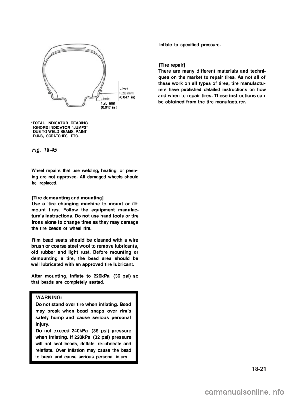
Limitl.Mmm(0.047 in)
1.20 mm(0.047 in 1
*TOTAL INDICATOR READINGIGNORE INDICATOR “JUMPS”DUE TO WELD SEAMS, PAINTRUNS, SCRATCHES, ETC.
Fig. 18-45
Wheel repairs that use welding, heating, or peen-
ing are not approved. All damaged wheels should
be replaced.
[Tire demounting and mounting]
Use a ‘tire changing machine to mount or de-
mount tires. Follow the equipment manufac-
ture’s instructions. Do not use hand tools or tire
irons alone to change tires as they may damage
the tire beads or wheel rim.
Rim bead seats should be cleaned with a wire
brush or coarse steel wool to remove lubricants,
old rubber and light rust. Before mounting or
demounting a tire, the bead area should be
well lubricated with an approved tire lubricant.
After mounting, inflate to 220kPa (32 psi) so
that beads are completely seated.
WARNING:
Do not stand over tire when inflating. Bead
may break when bead snaps over rim’s
safety hump and cause serious personal
injury.
Do not exceed 240kPa (35 psi) pressure
when inflating. If 220kPa (32 psi) pressure
will not seat beads, deflate, re-lubricate and
reinflate. Over inflation may cause the bead
to break and cause serious personal injury.1
Inflate to specified pressure.
[Tire repair]
There are many different materials and techni-
ques on the market to repair tires. As not all of
these work on all types of tires, tire manufactu-
rers have published detailed instructions on how
and when to repair tires. These instructions can
be obtained from the tire manufacturer.
18-21
Page 385 of 962

18-10. RECOMMENDED TORQUE SPECIFICATIONS
Fastening partsN-m
Tightening torque
kg-mlb-ft
Steering shaft nut25 - 402.5 - 4.018.5 - 28.5
ISteering shaft rubber joint boltI15-25I1.5- 2.5Ill.O- 18.0IL,
Steering shaft joint flangebolt20 - 302.0-3.014.5-21.5
Steering gear box nut70-907.0-9.051 .O-65.0
Drag rod castle nut30 - 703.0-7.022.0-50.5III
Tierodendcastlenut30-553.0-5.522.0-39.5
Tie rod end locknut70 - 1007.0- 10.051 .O-72.0
Steering damperstaynut18-281.8-2.813.5-20.0
Steeringdampernut35-553.5-5.525.5-39.5
Steeringdamperpin nut22-352.2-3.516.0-25.0
Steeringcolumnbolt & nut11-171.1-1.78.0-12.0
18-22
Page 386 of 962

SECTION 19
BRAKES
CONTENTS
19-1. GENERAL DESCRIPTION................................. 19-2
19-2. FRONT DISC BRAKE..................................... 19-14
19-3. REAR DRUM BRAKE..................................... 19-20
19-4. MASTER CYLINDER..................................... 19-27
19-5. BRAKE BOOSTER....................................... 19-30
19-6. PARKING BRAKE........................................ 19-38
19-7. BRAKE PIPES AND HOSES . . . . . . . . . . . . . . . . . . . . . . . . . . . . . . . 19-39
19-8. MAINTENANCE SERVICE . . . . . . . . . . . . . . . . . . . . . . . . . . . . . . . . 19-42
19-9. TORQUE SPECIFICATION.. . . . . . . . . . . . . . . . . . . . . . . . . . . . . . . 19-49
NOTE:
All brake fasteners are important attaching parts in that they could affect the performance
of vital parts and systems, and/or could result in major repair expense. They must be
replaced with one of same part number or with an equivalent part if replacement becomes
necessary. Do not use a replacement part of lesser quality or substitute design. Torque
values must be used as specified during reassembly to assure proper retention of all parts.
There is to be no welding as it may result in extensive damage and weakening of the
metal.
WARNING:
When servicing wheel brake parts, do not create dust by grinding, sanding brake linings,
or by cleaning wheel brake parts with a dry brush or with compressed air. Many wheel
brake parts contain asbestos fibers which can become airborned if dust is created dur-
ing servicing. Breathing dust containing asbestos fibers may cause serious bodily harm.
A water dampened cloth or water based solution should be used to remove any dust
on brake parts. Equipment is commercially available to perform this washing function.
These wet methods will prevent asbestos fibers from becoming airborne.
19-1
Page 387 of 962
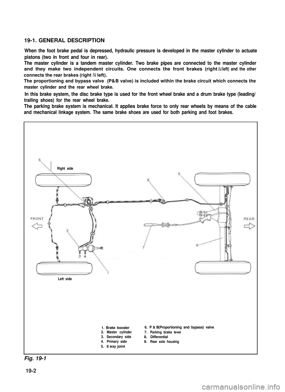
19-1. GENERAL DESCRIPTION
When the foot brake pedal is depressed, hydraulic pressure is developed in the master cylinder to actuate
pistons (two in front and four in rear).
The master cylinder is a tandem master cylinder. Two brake pipes are connected to the master cylinder
and they make two independent circuits. One connects the front brakes (right & left) and the other
connects the rear brakes (right & left).
The proportioning and bypass valve (P& B valve) is included within the brake circuit which connects the
master cylinder and the rear wheel brake.
In this brake system, the disc brake type is used for the front wheel brake and a drum brake type (leading/
trailing shoes) for the rear wheel brake.
The parking brake system is mechanical. It applies brake force to only rear wheels by means of the cable
and mechanical linkage system. The same brake shoes are used for both parking and foot brakes.
\Right side
Left side
1. Brake booster2.Master cylinder
3.Secondary side
4.Primary side
5.6 jointway
6. P & B (Proportioning and bypass) valve
7.Parking brake lever
8.Differential
9.Rear axle housing
Fig. 19-1
19-2
Page 388 of 962
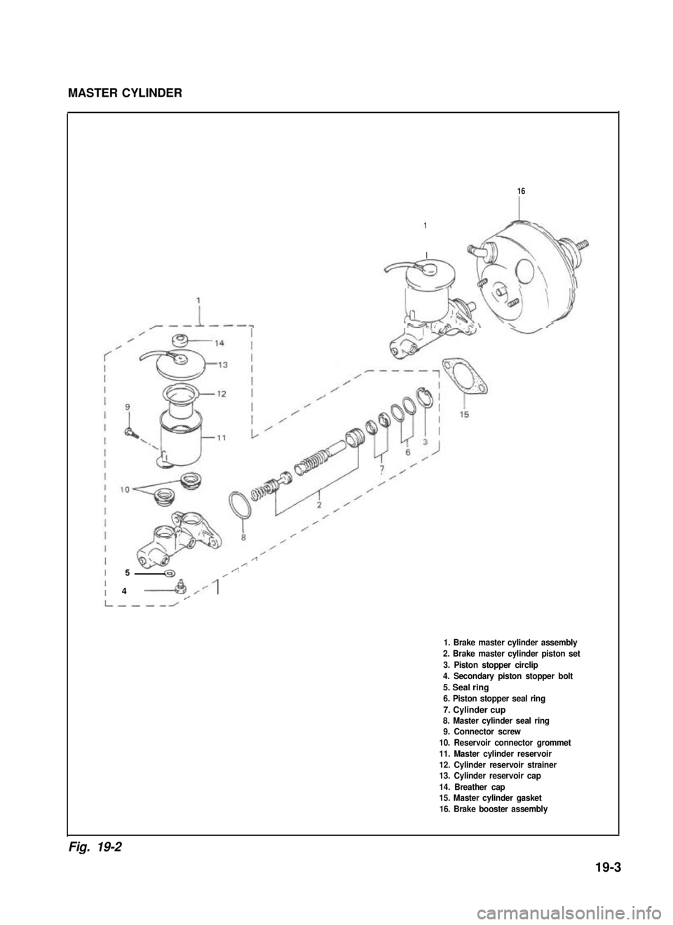
MASTER CYLINDER
16
1
I
/
//5//
4 ----A /’/
1. Brake master cylinder assembly
2. Brake master cylinder piston set
3. Piston stopper circlip
4. Secondary piston stopper bolt
5. Seal ring
6. Piston stopper seal ring
7. Cylinder cup8. Master cylinder seal ring9. Connector screw
10. Reservoir connector grommet
11. Master cylinder reservoir
12. Cylinder reservoir strainer13. Cylinder reservoir cap
14. Breather cap15. Master cylinder gasket
16. Brake booster assembly
Fig. 19-2
19-3
Page 389 of 962
![SUZUKI GRAND VITARA 1987 Service Repair Manual MASTER CYLINDER ASSEMBLY
[GENERAL DESCRIPTION]
The master cylinder has two pistons and three piston cups. Its hydraulic pressure is produced in the
primary (“a” in the below figure) and secondary SUZUKI GRAND VITARA 1987 Service Repair Manual MASTER CYLINDER ASSEMBLY
[GENERAL DESCRIPTION]
The master cylinder has two pistons and three piston cups. Its hydraulic pressure is produced in the
primary (“a” in the below figure) and secondary](/img/20/57437/w960_57437-388.png)
MASTER CYLINDER ASSEMBLY
[GENERAL DESCRIPTION]
The master cylinder has two pistons and three piston cups. Its hydraulic pressure is produced in the
primary (“a” in the below figure) and secondary (“b”) chambers. The hydraulic pressure produced in the
primary chamber (“a”) acts on the front wheel brakes (right & left).
Also, the hydraulic pressure produced in the secondary chamber (“b”) acts on the rear wheel brakes
(right & left).
NOTE:
Replace all components included in repair kits to service this master cylinder. Lubricate rubber parts with
clean, fresh brake fluid to ease assembly. Do not use lubricated shop air on brake parts as damage to rubber
components may result. If any hydraulic component is removed or brake line disconnected, bleed the
brake system. The torque values specified are for dry, unlubricated fasteners.
1.Piston stopper circllp
2.Piston stopper
3.Piston stopper sealing
4.Primary piston
5.Piston cup
6.Secondary piston pressure cup
7.Piston cup
8Secondary piston
9.Return spring secondary seat
10.Secondary piston return spring
11.Secondary piston stopper bolt
12.Master cylinder body
A :Primary piston
BSecondary piston
Fig. 19-3
[Master cylinder OPERATION]
Normal operation
Depressing the brake pedal forces the primary piston“A” to move to the left in the below figure and
consequently the hydraulic pressure is produced in the chamber “a”.
By means of this pressure and the return spring force, the secondary piston “B” is also pushed to the left
and thus the hydraulic pressure is produced in the chamber “b”.
Fig. 19-3-1
19-4
Page 390 of 962
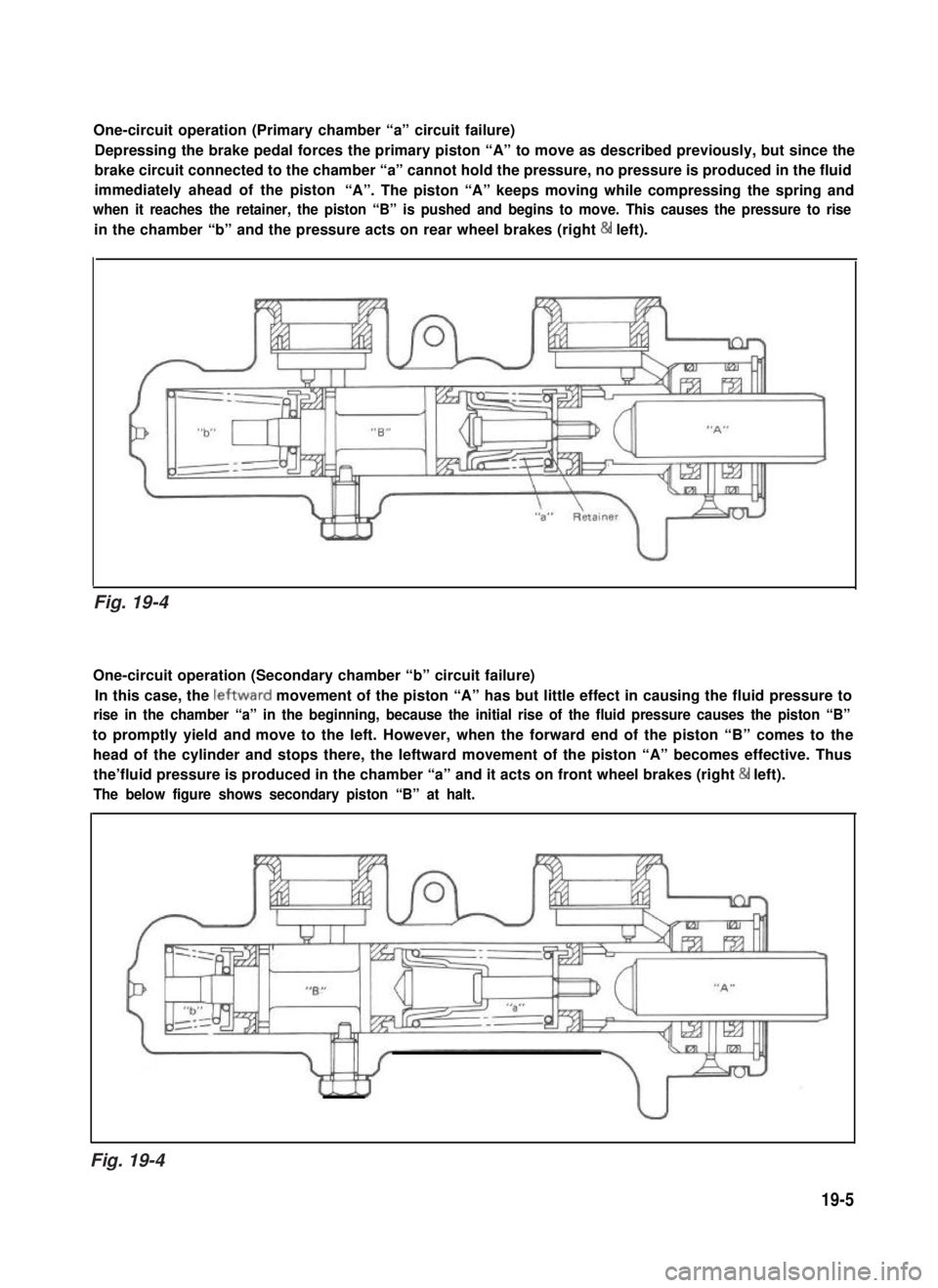
One-circuit operation (Primary chamber “a” circuit failure)
Depressing the brake pedal forces the primary piston “A” to move as described previously, but since the
brake circuit connected to the chamber “a” cannot hold the pressure, no pressure is produced in the fluid
immediately ahead of the piston“A”. The piston “A” keeps moving while compressing the spring and
when it reaches the retainer, the piston “B” is pushed and begins to move. This causes the pressure to rise
in the chamber “b” and the pressure acts on rear wheel brakes (right & left).
One-circuit operation (Secondary chamber “b” circuit failure)
In this case, the leftward movement of the piston “A” has but little effect in causing the fluid pressure to
rise in the chamber “a” in the beginning, because the initial rise of the fluid pressure causes the piston “B”
to promptly yield and move to the left. However, when the forward end of the piston “B” comes to the
head of the cylinder and stops there, the Ieftward movement of the piston “A” becomes effective. Thus
the’fluid pressure is produced in the chamber “a” and it acts on front wheel brakes (right & left).
The below figure shows secondary piston “B” at halt.
19-5
Fig. 19-4
Fig. 19-4