SUZUKI SWIFT 2000 1.G RG413 Service Workshop Manual
[x] Cancel search | Manufacturer: SUZUKI, Model Year: 2000, Model line: SWIFT, Model: SUZUKI SWIFT 2000 1.GPages: 698, PDF Size: 16.01 MB
Page 201 of 698

3D-8 FRONT SUSPENSION
Tighten strut nut to specified torque by using special tools.
Tightening torque
Strut nut (a) : 50 N·m (5.0 kg-m, 36.5 lb-ft)
Special tool
(A) : 09900-00411
(B) : 09900-00414
(C) : 09945-26010
INSTALLATION
Install strut assembly by reversing removal procedure, noting the
following instructions.
Insert bolts in such direction as shown in figure.
Tighten all fasteners to specified torque.
Tightening torque
Strut bracket nut (a) : 105 N·m (10.5 kg-m, 76.0 lb-ft)
Strut support nut (b) : 23 N·m (2.3 kg-m, 17.0 lb-ft)
Tighten wheel nut to specified torque.
Tightening torque
Wheel nut : 85 N·m (8.5 kg-m, 61.5 lb-ft)
After installation, confirm front end (wheel) alignment refer-
ring to Section 3A.
NOTE:
Don’t twist brake hose when installing it.
Install E-ring (1) as far as it fits to bracket (2) as shown
in figure.
Page 202 of 698

FRONT SUSPENSION 3D-9
STABILIZER BAR AND/OR BUSHINGS
REMOVAL
1) Hoist vehicle and allow front suspension control arms to
hang free.
2) Remove front wheels.
3) Remove, stabilizer bar sprit pin (3) and nut (1) and washer
(2).
4) Remove stabilizer bar mounting bracket bolts (1).
5) Remove stabilizer bar (2).
1. Stabilizer bar 4. Bushing 7. Stabilizer bar mounting bracket bolt Tightening torque
2. Mount bracket 5. Washer 8. Sprit pin Do not reuse.
3. Mount bushing 6. Stabilizer bar nut
NOTE:
If it is hard to remove stabilizer bar, set tires in contact
with ground (with suspension compressed).
F. FORWARD
Page 203 of 698

3D-10 FRONT SUSPENSION
INSTALLATION
For installation, reverse removal procedure, noting the following
instructions.
Install stabilizer bar (2) so that paint mark (1) on it comes to
the right side of vehicle.
There is a paint mark (1) of stabilizer bar. Install stabilizer
bar mount bracket to inside of stabilizer bar at that mark.
Install mount bracket (1) so that its oblong hole side (2)
comes to the rear.
Tighten stabilizer bar mounting bracket bolts to specified
torque.
Tightening torque
Stabilizer bar mounting bracket bolt
: 45 N·m (4.5 kg-m, 32.5 lb-ft)
Tighten stabilizer bar nut (1) to specified torque.
Tightening torque
Stabilizer bar nut (a) : 65 N·m (6.5 kg-m, 47.0 lb-ft)
Install new sprit pin (2).
Tighten wheel nut to specified torque.
Tightening torque
Wheel nut : 85 N·m (8.5 kg-m, 61.5 lb-ft)
3. Mark
F: Forward
Page 204 of 698

FRONT SUSPENSION 3D-11
WHEEL HUB AND STEERING KNUCKLE
REMOVAL
1) Hoist vehicle and remove wheel.
2) Uncaulk drive shaft nut (1).
3) Depress foot brake pedal and hold it there. Remove drive
shaft nut (1).
4) Remove caliper carrier bolts.
5) Remove caliper (1) with carrier.
6) Pull brake disc (2) off by using two 8 mm bolts.
1. Front wheel hub 4. Steering knuckle Tightening torque
2. Circlip 5. Drive shaft nut
: Calk, after tightening.Do not reuse.
3. Wheel bearing
: Face grooved rubber seal side to wheel hub.6. Hub bolt
NOTE:
Hang removed caliper with a wire hook or the like (3) so
as to prevent brake hose (4) from bending and twisting
excessively or being pulled.
Don’t operate brake pedal with pads removed.
Page 205 of 698

3D-12 FRONT SUSPENSION
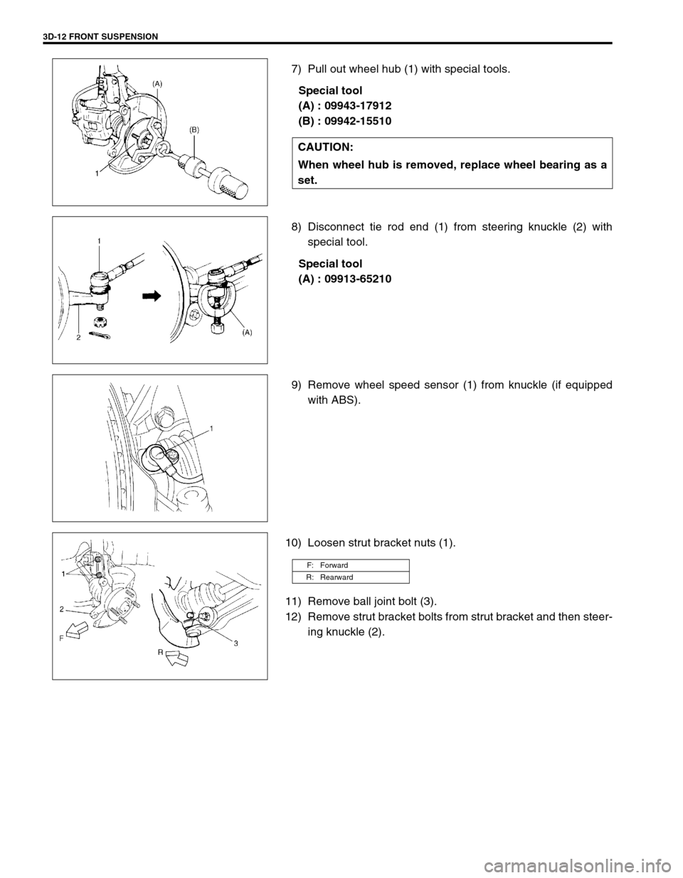
7) Pull out wheel hub (1) with special tools.
Special tool
(A) : 09943-17912
(B) : 09942-15510
8) Disconnect tie rod end (1) from steering knuckle (2) with
special tool.
Special tool
(A) : 09913-65210
9) Remove wheel speed sensor (1) from knuckle (if equipped
with ABS).
10) Loosen strut bracket nuts (1).
11) Remove ball joint bolt (3).
12) Remove strut bracket bolts from strut bracket and then steer-
ing knuckle (2). CAUTION:
When wheel hub is removed, replace wheel bearing as a
set.
F: Forward
R: Rearward
Page 206 of 698

FRONT SUSPENSION 3D-13
DISASSEMBLY
1) Uncaulk and remove dust cover (1).
2) Remove circlip.
3) Using hydraulic press (1) and special tool, remove wheel
bearing.
Special tool
(A) : 09913-75810
4) Remove wheel bearing outside inner race (1).
Special tool
(C) : 09913-61110
(D) : 09925-88210
5) Remove hub bolts (1).
CAUTION:
When installing wheel bearing, replace it with new one.
CAUTION:
Never remove bolt unless replacement is necessary.
Be sure to use a new bolt for replacement.
Page 207 of 698

3D-14 FRONT SUSPENSION
ASSEMBLY
1) Face grooved rubber seal side (1) of new wheel bearing (2)
upward as shown in figure and press-fit it into knuckle using
special tool.
Special tool
(A) : 09913-75520
2) Install circlip (1).
3) Drive in dust cover so that dimensions “a” and “b” become
equal as shown in figure.
4) Caulk with a punch.CAUTION:
When replacing bearing, inner races or outer race, be
sure to replace them with new ones as a set.
CAUTION:
When drive in dust cover, be careful not to deform it.
Page 208 of 698

FRONT SUSPENSION 3D-15
5) Insert new stud bolt (1) in hub hole. Rotate stud bolt slowly to
assure that serrations are aligned with those made by origi-
nal bolt.
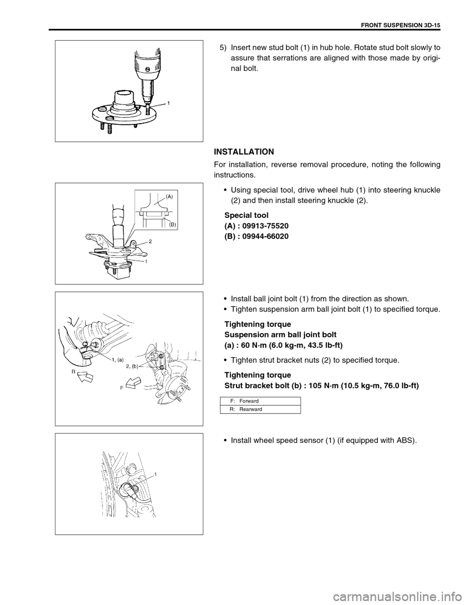
INSTALLATION
For installation, reverse removal procedure, noting the following
instructions.
Using special tool, drive wheel hub (1) into steering knuckle
(2) and then install steering knuckle (2).
Special tool
(A) : 09913-75520
(B) : 09944-66020
Install ball joint bolt (1) from the direction as shown.
Tighten suspension arm ball joint bolt (1) to specified torque.
Tightening torque
Suspension arm ball joint bolt
(a) : 60 N·m (6.0 kg-m, 43.5 lb-ft)
Tighten strut bracket nuts (2) to specified torque.
Tightening torque
Strut bracket bolt (b) : 105 N·m (10.5 kg-m, 76.0 lb-ft)
Install wheel speed sensor (1) (if equipped with ABS).
F: Forward
R: Rearward
Page 209 of 698

3D-16 FRONT SUSPENSION
Connect tie rod end (1) to steering knuckle (2) and tighten tie
rod end castle nut (3) to specified torque.
Tightening torque
The rod end castle nut (a) : 43 N·m (4.3 kg-m, 31.5 lb-ft)
Install new split pin (4).
Install brake disc (2) and brake caliper (3).
Tighten brake caliper bolt to specified torque.
Tightening torque
Brake caliper bolt : 85 N·m (8.5 kg-m, 61.5 lb-ft)
Depress foot brake pedal and hold it there.
Tighten new drive shaft nut (1) to specified torque.
Tightening torque
Drive shaft nut (a) : 175 N·m (17.5 kg-m, 127.0 lb-ft)
Caulk drive shaft nut (1) as shown.
Caulking specification
“a” : 0.5 mm (0.02 in.) or more
Tightening wheel nut to specified torque.
Tightening torque
Wheel nut : 85 N·m (8.5 kg-m, 61.5 lb-ft)
SUSPENSION CONTROL ARM / BUSHING
REMOVAL
1) Remove stabilizer bar. Refer to “STABILIZER BAR AND/OR
BUSHINGS” in this section.
2) Remove suspension control arm ball joint bolt (1).
CAUTION:
Never reuse drive shaft nut (1).
CAUTION:
Be careful while caulking nut so that no crack will occur
in caulked part of nut. Cracked nut must be replaced with
new one.
F: Forward
Page 210 of 698

FRONT SUSPENSION 3D-17
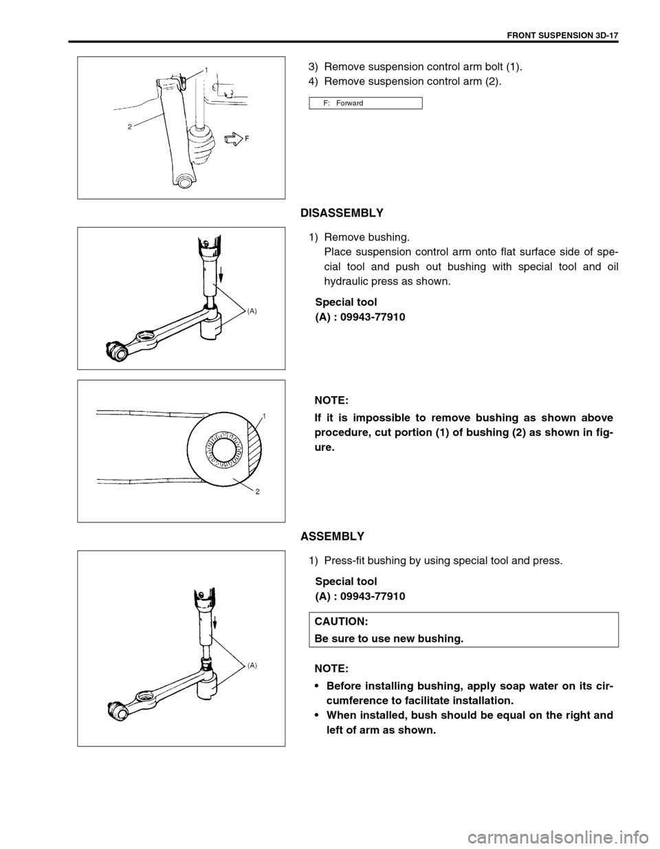
3) Remove suspension control arm bolt (1).
4) Remove suspension control arm (2).
DISASSEMBLY
1) Remove bushing.
Place suspension control arm onto flat surface side of spe-
cial tool and push out bushing with special tool and oil
hydraulic press as shown.
Special tool
(A) : 09943-77910
ASSEMBLY
1) Press-fit bushing by using special tool and press.
Special tool
(A) : 09943-77910
F: Forward
NOTE:
If it is impossible to remove bushing as shown above
procedure, cut portion (1) of bushing (2) as shown in fig-
ure.
CAUTION:
Be sure to use new bushing.
NOTE:
Before installing bushing, apply soap water on its cir-
cumference to facilitate installation.
When installed, bush should be equal on the right and
left of arm as shown.