TOYOTA CAMRY 2000 Service Repair Manual
CAMRY 2000
TOYOTA
TOYOTA
https://www.carmanualsonline.info/img/14/57447/w960_57447-0.png
TOYOTA CAMRY 2000 Service Repair Manual
Trending: oil reset, center console, instrument panel, Speaker, coil wiring, key, CD player
Page 641 of 4770
mm in.
10
200.39
0.79
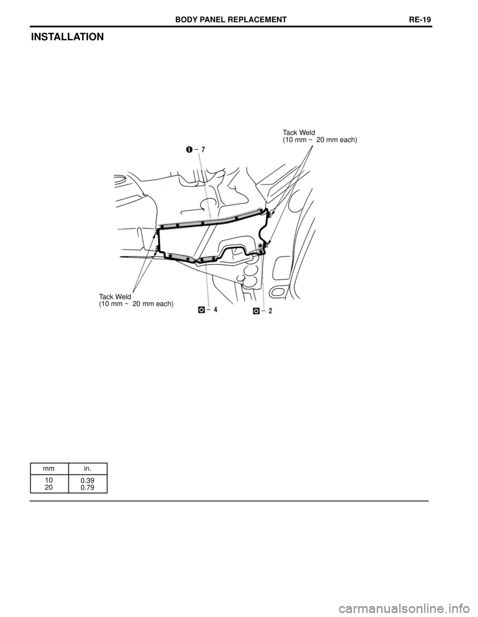
INSTALLATION
Tack Weld
(10 mm ~ 20 mm each)
Tack Weld
(10 mm ~ 20 mm each)
BODY PANEL REPLACEMENTRE-19
Page 642 of 4770
mm in.
20
2100.79
8.27
FRONT SIDE MEMBER (CUT±P)
20 mm
REMOVAL (With the front fender front apron removed.)
[LH]
[RH]
20 mm
Cut and Join Location
Cut and Join Location
Cut and Join Location
[LH only]
210 mm
Battery Carrier Support
1. Cut and join the part at the locations as shown
above.
HINT:
1) Be careful not to damage the reinforcement
when cutting the member.
2) Before cutting the side member, remove the
battery carrier support. (LH only)
BODY PANEL REPLACEMENTRE-20
Page 643 of 4770
INSTALLATION
[LH]
[RH]
Butt Weld
Butt Weld
Front Bumper Mounting
Reinforcement
Front Suspension Member
Mounting Bracket
[LH only]
Butt Weld
1. Temporarily install the new parts and mea-
sure each part in accordance with the body
dimension diagram.
BODY PANEL REPLACEMENTRE-21
Page 644 of 4770
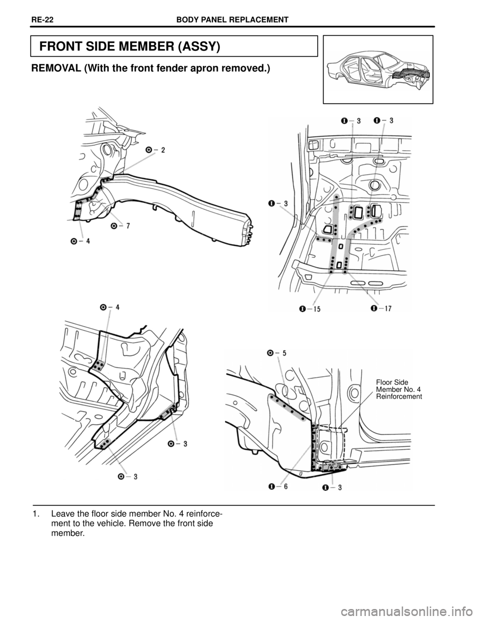
FRONT SIDE MEMBER (ASSY)
REMOVAL (With the front fender apron removed.)
Floor Side
Member No. 4
Reinforcement
1. Leave the floor side member No. 4 reinforce-
ment to the vehicle. Remove the front side
member.
BODY PANEL REPLACEMENTRE-22
Page 645 of 4770
INSTALLATION
1. Temporarily install the new parts and mea-
sure each part in accordance with the body
dimension diagram.
HINT: Make sure each measurement is correct, as
this parts affects the front wheel alignment.
BODY PANEL REPLACEMENTRE-23
Page 646 of 4770
mm in.
5
15
30
50
1200.20
0.59
1.18
1.97
4.72
FRONT BODY PILLAR (CUT)
REMOVAL (With the cowl top side panel removed.)
[Cut and Join Location]
120 mm
50 mm
50 mm Cut and Join
Location
30 mm
Cut with disc
sander etc.
Cut and Join Location
[Cut Location for Supply Parts]
[Cut and Join Location]
5 mm
15 mm
Center Body Pillar Lower
Reinforcement
Rocker Panel No. 5 Reinforcement
1. Cut and join the parts at the locations shown
above.
HINT:
1. Shift the each cut and join locations of the out-
er pillar, reinforcement, inner pillar and roof
drip channel.
2. Shift the each cut and join locations of the out-
er panel, center body pillar lower reinforce-
ment and rocker panel No. 5 reinforcement.
BODY PANEL REPLACEMENTRE-24
Page 647 of 4770
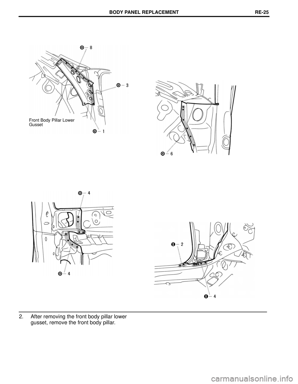
Front Body Pillar Lower
Gusset
2. After removing the front body pillar lower
gusset, remove the front body pillar.
BODY PANEL REPLACEMENTRE-25
Page 648 of 4770
mm in.
40
11 5
2001.57
4.53
7.87
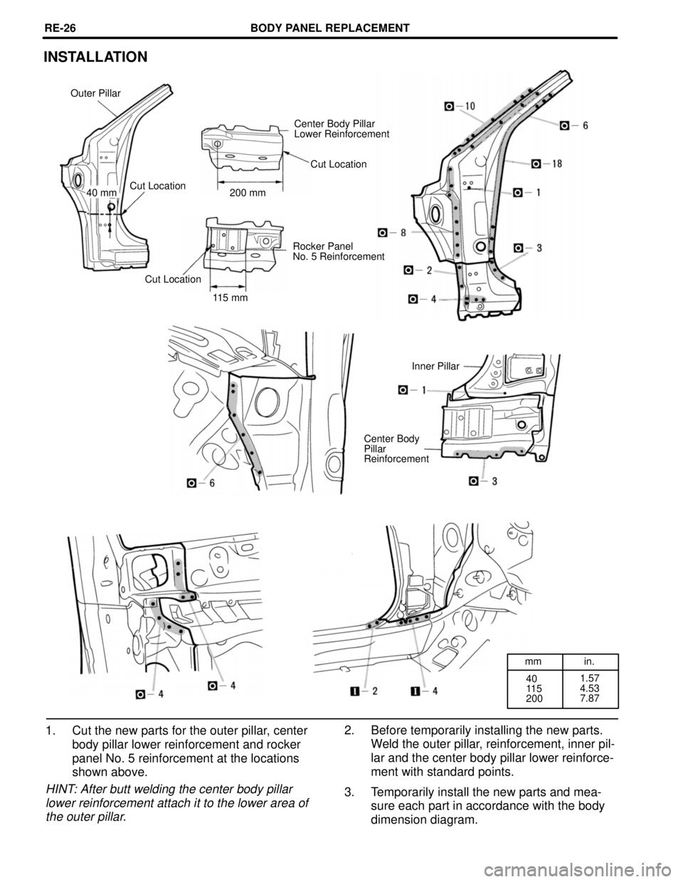
INSTALLATION
Outer Pillar
Center Body Pillar
Lower Reinforcement
Cut Location
Cut Location
40 mm 200 mm
Rocker Panel
No. 5 Reinforcement
Cut Location
115 mm
Inner Pillar
Center Body
Pillar
Reinforcement
2. Before temporarily installing the new parts.
Weld the outer pillar, reinforcement, inner pil-
lar and the center body pillar lower reinforce-
ment with standard points.
3. Temporarily install the new parts and mea-
sure each part in accordance with the body
dimension diagram. 1. Cut the new parts for the outer pillar, center
body pillar lower reinforcement and rocker
panel No. 5 reinforcement at the locations
shown above.
HINT: After butt welding the center body pillar
lower reinforcement attach it to the lower area of
the outer pillar.
BODY PANEL REPLACEMENTRE-26
Page 649 of 4770
mmin.
10
15
25
1000.39
0.59
0.98
3.94 Butt Weld
Butt Weld
100 mm
Butt Weld
Butt Weld
(Rocker panel No. 5
Reinforcement.)
Butt Weld
Tack Weld
(10 mm ~ 15 mm each)
Butt Weld
(Center Body
Pillar Lower
Reinforcement)
25 mm
Butt Weld
(Outer Pillar)
Butt Weld
[Foamed Material
Application Areas]
4. Before welding the new parts, check the fit of
the front door, front fender and windshield
glass.
5. Cut the upper part of the outer pillar 100 mm
(3.94 in.) from its cut and join location and af-
ter butt welding the reinforcement, attach the
outer pillar.6. Cut the center body pillar lower reinforce-
ment 25 mm (0.98 in.) from its previous cut
and joining location.
Butt weld the rocker panel No. 5 reinforce-
ment and butt weld the center body pillar
lower reinforcement.
7. Apply foamed material to the pillar section.
BODY PANEL REPLACEMENTRE-27
Page 650 of 4770
Trending: power windows, headrest, fuel cap, traction control, height adjustment, tow, technical specifications
![TOYOTA CAMRY 2000 Service Repair Manual mm in.
20
2100.79
8.27
FRONT SIDE MEMBER (CUT±P)
20 mm
REMOVAL (With the front fender front apron removed.)
[LH]
[RH]
20 mm
Cut and Join Location
Cut and Join Location
Cut and Join Location
[LH only] TOYOTA CAMRY 2000 Service Repair Manual mm in.
20
2100.79
8.27
FRONT SIDE MEMBER (CUT±P)
20 mm
REMOVAL (With the front fender front apron removed.)
[LH]
[RH]
20 mm
Cut and Join Location
Cut and Join Location
Cut and Join Location
[LH only]](/img/14/57447/w960_57447-641.png)
![TOYOTA CAMRY 2000 Service Repair Manual INSTALLATION
[LH]
[RH]
Butt Weld
Butt Weld
Front Bumper Mounting
Reinforcement
Front Suspension Member
Mounting Bracket
[LH only]
Butt Weld
1. Temporarily install the new parts and mea-
sure each part TOYOTA CAMRY 2000 Service Repair Manual INSTALLATION
[LH]
[RH]
Butt Weld
Butt Weld
Front Bumper Mounting
Reinforcement
Front Suspension Member
Mounting Bracket
[LH only]
Butt Weld
1. Temporarily install the new parts and mea-
sure each part](/img/14/57447/w960_57447-642.png)

![TOYOTA CAMRY 2000 Service Repair Manual mm in.
5
15
30
50
1200.20
0.59
1.18
1.97
4.72
FRONT BODY PILLAR (CUT)
REMOVAL (With the cowl top side panel removed.)
[Cut and Join Location]
120 mm
50 mm
50 mm Cut and Join
Location
30 mm
Cut with di TOYOTA CAMRY 2000 Service Repair Manual mm in.
5
15
30
50
1200.20
0.59
1.18
1.97
4.72
FRONT BODY PILLAR (CUT)
REMOVAL (With the cowl top side panel removed.)
[Cut and Join Location]
120 mm
50 mm
50 mm Cut and Join
Location
30 mm
Cut with di](/img/14/57447/w960_57447-645.png)
