TOYOTA CAMRY V20 1986 Service Information
CAMRY V20 1986
TOYOTA
TOYOTA
https://www.carmanualsonline.info/img/14/57449/w960_57449-0.png
TOYOTA CAMRY V20 1986 Service Information
Trending: battery, lights, engine oil, brake fluid, manual radio set, length, transmission
Page 1371 of 2389
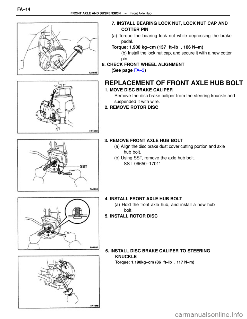
7. INSTALL BEARING LOCK NUT, LOCK NUT CAP AND
COTTER PIN
(a) Torque the bearing lock nut while depressing the brake
pedal.
Torque: 1,900 kg±cm (137 ft±lb , 186 N±m)
(b) Install the lock nut cap, and secure it with a new cotter
pin.
8. CHECK FRONT WHEEL ALIGNMENT
(See page FA ± 3)
REPLACEMENT OF FRONT AXLE HUB BOLT
1. MOVE DISC BRAKE CALIPER
Remove the disc brake caliper from the steering knuckle and
suspended it with wire.
2. REMOVE ROTOR DISC
3. REMOVE FRONT AXLE HUB BOLT
(a) Align the disc brake dust cover cutting portion and axle
hub bolt.
(b) Using SST, remove the axle hub bolt.
SST 09650±17011
6. INSTALL DISC BRAKE CALIPER TO STEERING
KNUCKLE
Torque: 1,190kg±cm (86 ft±lb , 117 N±m)
4. INSTALL FRONT AXLE HUB BOLT
(a) Hold the front axle hub, and install a new hub
bolt.
5. INSTALL ROTOR DISC
± FRONT AXLE AND SUSPENSIONFront Axle HubFA±14
Page 1372 of 2389
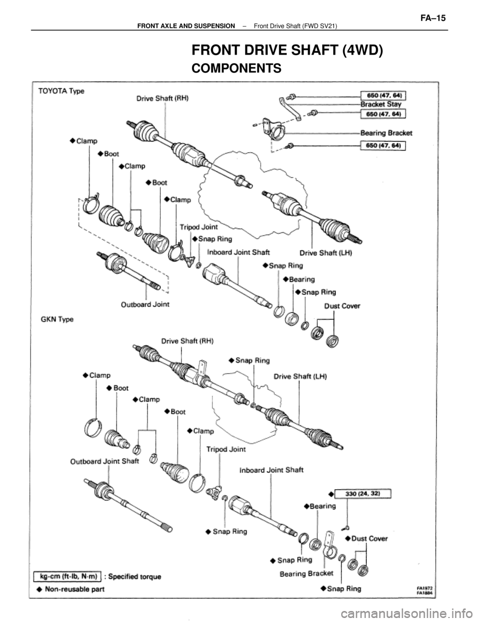
FRONT DRIVE SHAFT (4WD)
COMPONENTS
± FRONT AXLE AND SUSPENSIONFront Drive Shaft (FWD SV21)FA±15
Page 1373 of 2389
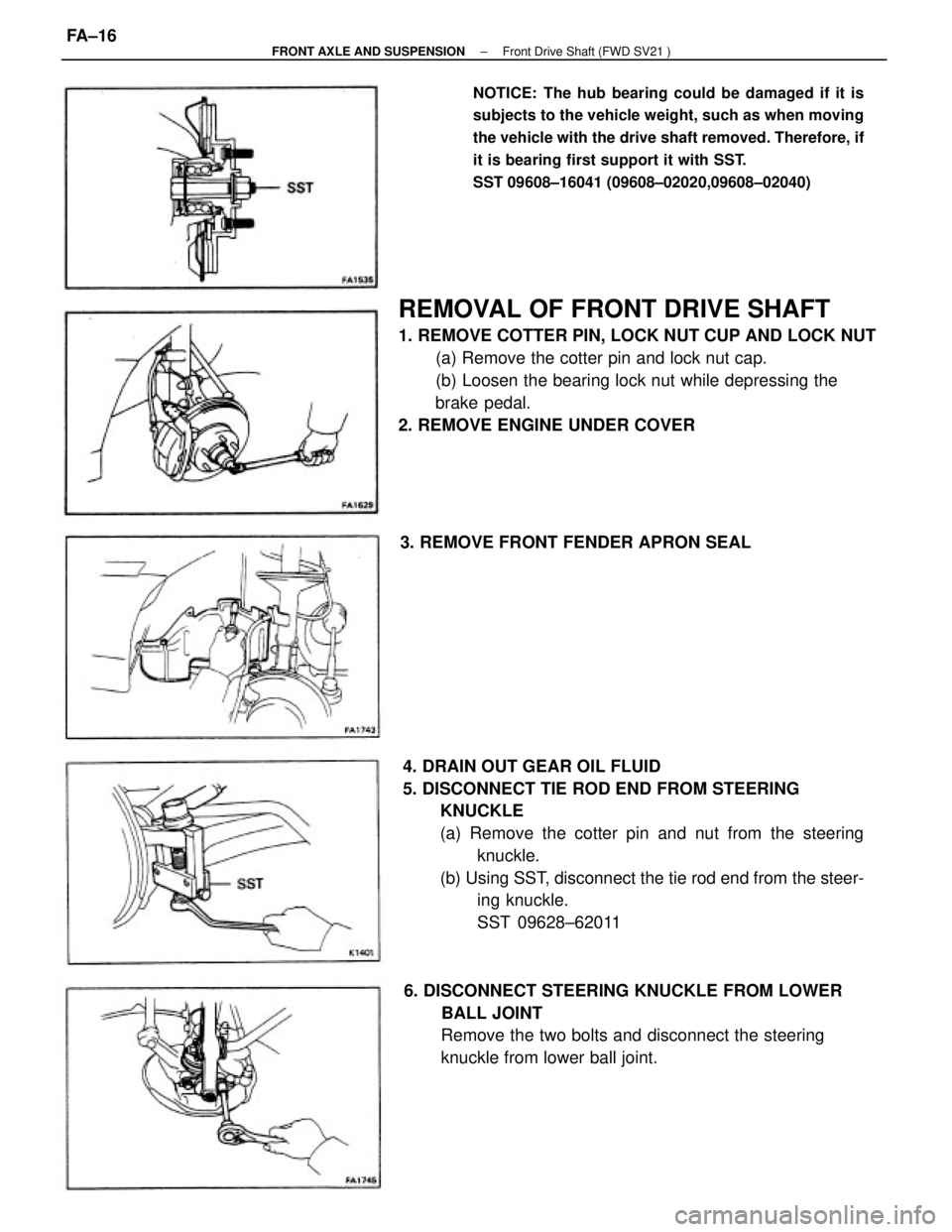
REMOVAL OF FRONT DRIVE SHAFT
1. REMOVE COTTER PIN, LOCK NUT CUP AND LOCK NUT
(a) Remove the cotter pin and lock nut cap.
(b) Loosen the bearing lock nut while depressing the
brake pedal.
2. REMOVE ENGINE UNDER COVER
4. DRAIN OUT GEAR OIL FLUID
5. DISCONNECT TIE ROD END FROM STEERING
KNUCKLE
(a) Remove the cotter pin and nut from the steering
knuckle.
(b) Using SST, disconnect the tie rod end from the steer-
ing knuckle.
SST 09628±62011
NOTICE: The hub bearing could be damaged if it is
subjects to the vehicle weight, such as when moving
the vehicle with the drive shaft removed. Therefore, if
it is bearing first support it with SST.
SST 09608±16041 (09608±02020,09608±02040)
6. DISCONNECT STEERING KNUCKLE FROM LOWER
BALL JOINT
Remove the two bolts and disconnect the steering
knuckle from lower ball joint. 3. REMOVE FRONT FENDER APRON SEAL
± FRONT AXLE AND SUSPENSIONFront Drive Shaft (FWD SV21 )FA±16
Page 1374 of 2389
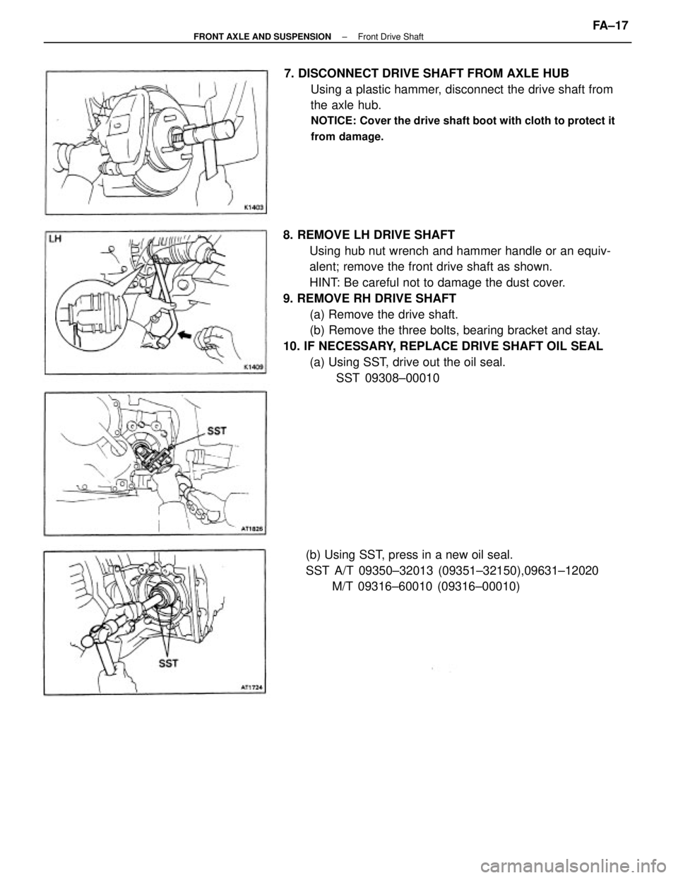
8. REMOVE LH DRIVE SHAFT
Using hub nut wrench and hammer handle or an equiv-
alent; remove the front drive shaft as shown.
HINT: Be careful not to damage the dust cover.
9. REMOVE RH DRIVE SHAFT
(a) Remove the drive shaft.
(b) Remove the three bolts, bearing bracket and stay.
10. IF NECESSARY, REPLACE DRIVE SHAFT OIL SEAL
(a) Using SST, drive out the oil seal.
SST 09308±00010 7. DISCONNECT DRIVE SHAFT FROM AXLE HUB
Using a plastic hammer, disconnect the drive shaft from
the axle hub.
NOTICE: Cover the drive shaft boot with cloth to protect it
from damage.
(b) Using SST, press in a new oil seal.
SST A/T 09350±32013 (09351±32150),09631±12020
M/T 09316±60010 (09316±00010)
± FRONT AXLE AND SUSPENSIONFront Drive ShaftFA±17
Page 1375 of 2389
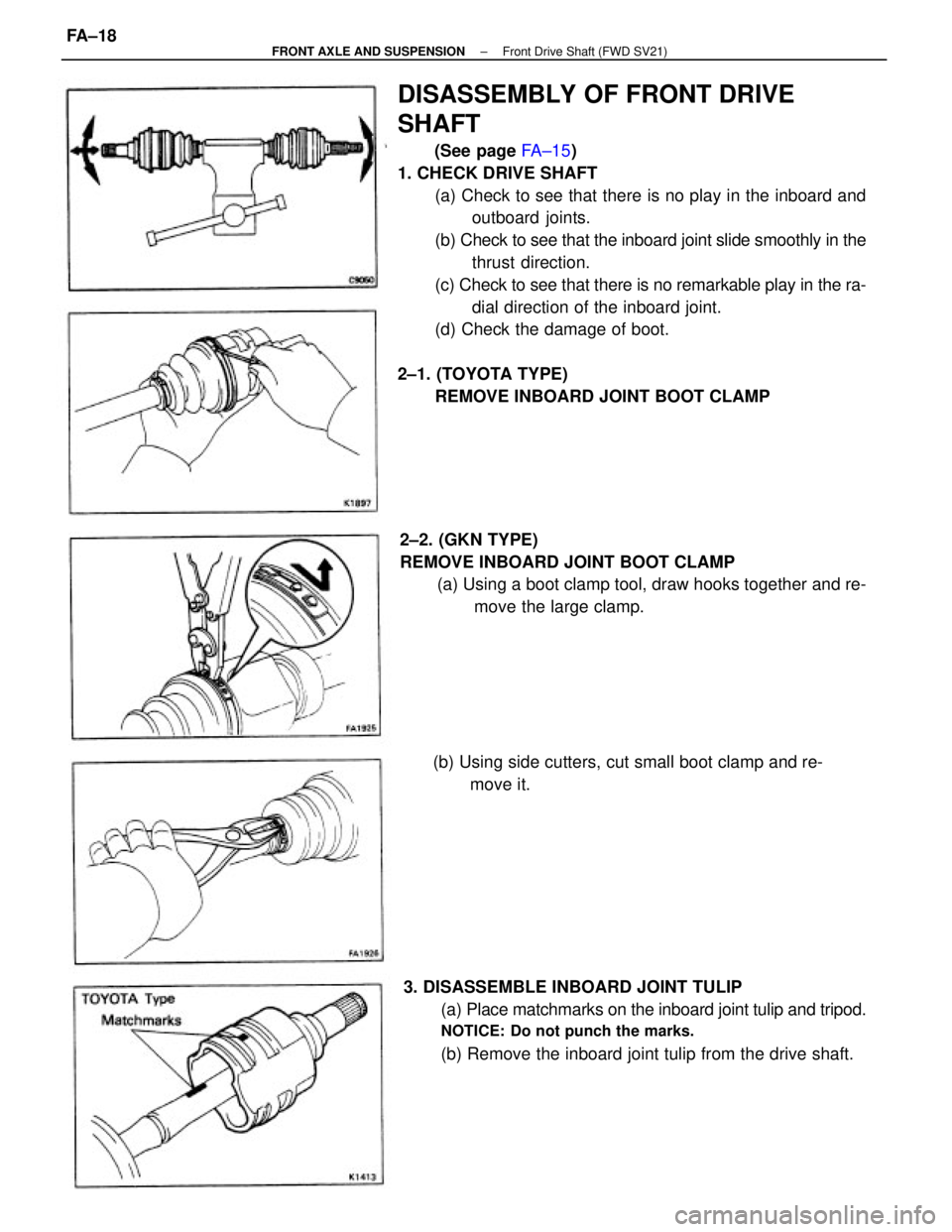
DISASSEMBLY OF FRONT DRIVE
SHAFT
(See page FA±15)
1. CHECK DRIVE SHAFT
(a) Check to see that there is no play in the inboard and
outboard joints.
(b) Check to see that the inboard joint slide smoothly in the
thrust direction.
(c) Check to see that there is no remarkable play in the ra-
dial direction of the inboard joint.
(d) Check the damage of boot.
2±1. (TOYOTA TYPE)
REMOVE INBOARD JOINT BOOT CLAMP
3. DISASSEMBLE INBOARD JOINT TULIP
(a) Place matchmarks on the inboard joint tulip and tripod.
NOTICE: Do not punch the marks.
(b) Remove the inboard joint tulip from the drive shaft. 2±2. (GKN TYPE)
REMOVE INBOARD JOINT BOOT CLAMP
(a) Using a boot clamp tool, draw hooks together and re-
move the large clamp.
(b) Using side cutters, cut small boot clamp and re-
move it.
± FRONT AXLE AND SUSPENSIONFront Drive Shaft (FWD SV21)FA±18
Page 1376 of 2389
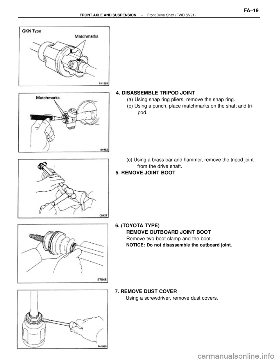
4. DISASSEMBLE TRIPOD JOINT
(a) Using snap ring pliers, remove the snap ring.
(b) Using a punch, place matchmarks on the shaft and tri-
pod.
6. (TOYOTA TYPE)
REMOVE OUTBOARD JOINT BOOT
Remove two boot clamp and the boot.
NOTICE: Do not disassemble the outboard joint.
(c) Using a brass bar and hammer, remove the tripod joint
from the drive shaft.
5. REMOVE JOINT BOOT
7. REMOVE DUST COVER
Using a screwdriver, remove dust covers.
± FRONT AXLE AND SUSPENSIONFront Drive Shaft (FWD SV21)FA±19
Page 1377 of 2389
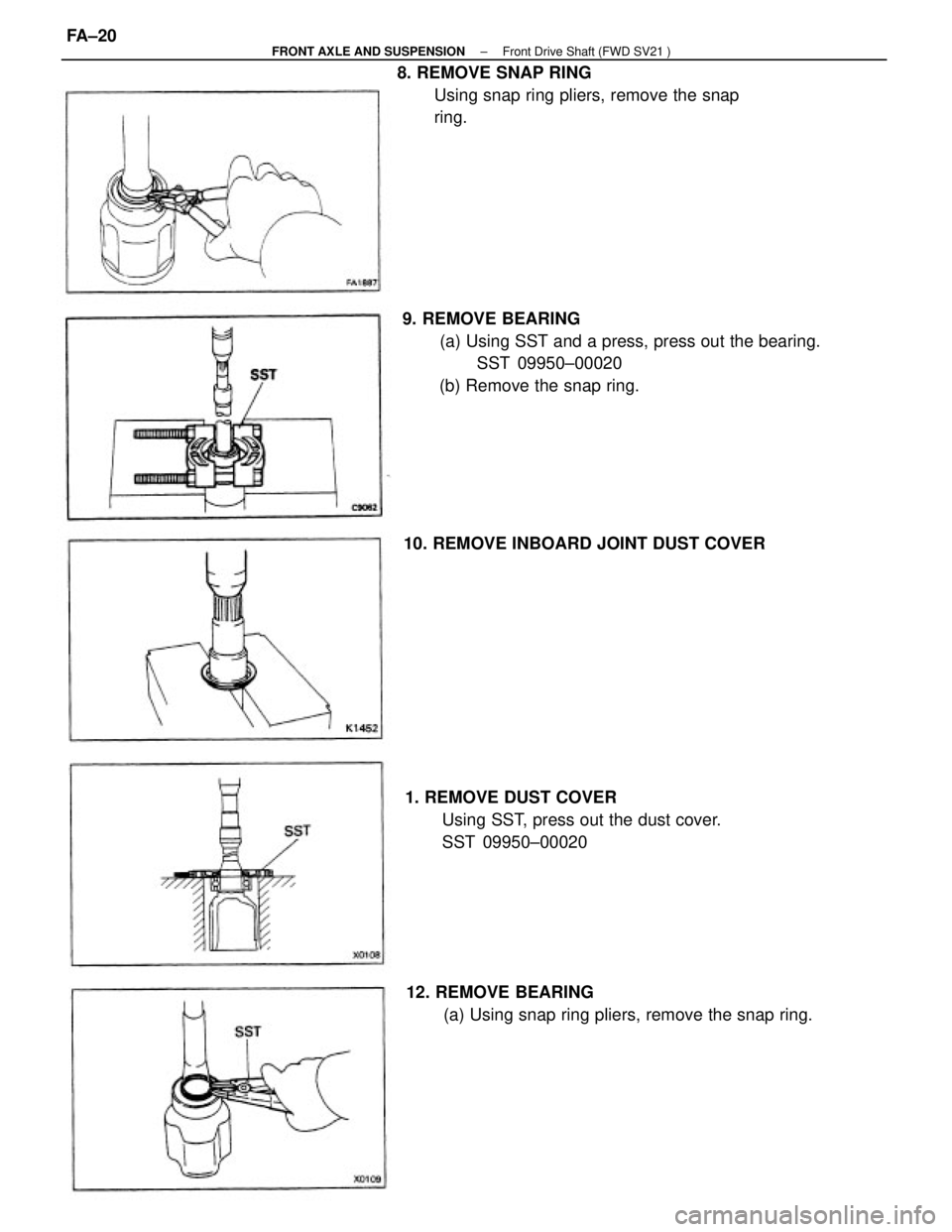
9. REMOVE BEARING
(a) Using SST and a press, press out the bearing.
SST 09950±00020
(b) Remove the snap ring. 8. REMOVE SNAP RING
Using snap ring pliers, remove the snap
ring.
1. REMOVE DUST COVER
Using SST, press out the dust cover.
SST 09950±00020
12. REMOVE BEARING
(a) Using snap ring pliers, remove the snap ring. 10. REMOVE INBOARD JOINT DUST COVER
± FRONT AXLE AND SUSPENSIONFront Drive Shaft (FWD SV21 )FA±20
Page 1378 of 2389
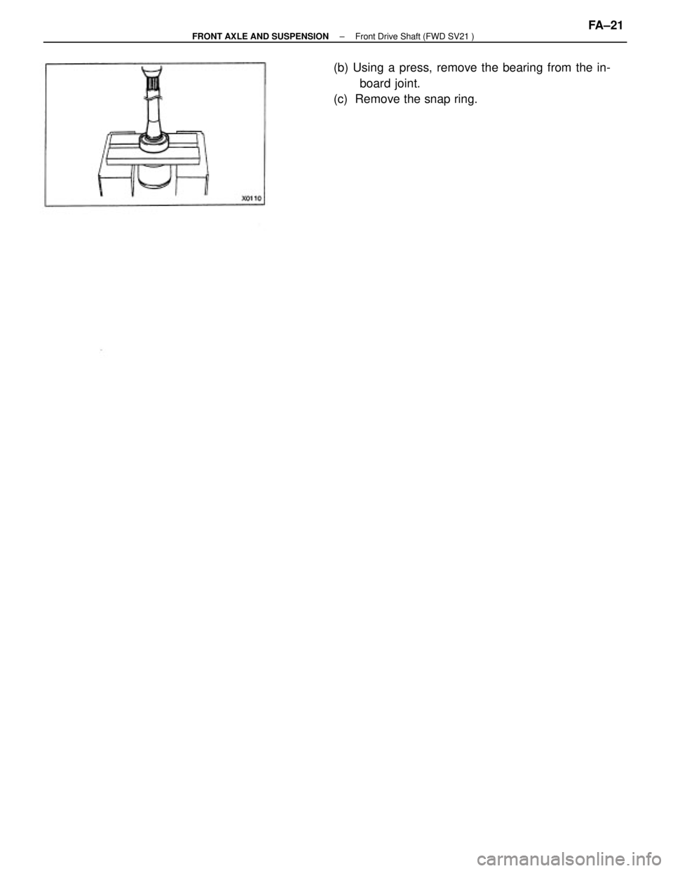
(b) Using a press, remove the bearing from the in-
board joint.
(c) Remove the snap ring.
± FRONT AXLE AND SUSPENSIONFront Drive Shaft (FWD SV21 )FA±21
Page 1379 of 2389
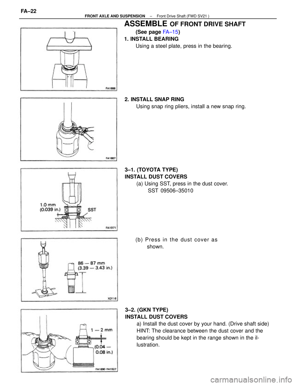
3±2. (GKN TYPE)
INSTALL DUST COVERS
a) Install the dust cover by your hand. (Drive shaft side)
HINT: The clearance between the dust cover and the
bearing should be kept in the range shown in the il-
lustration.
ASSEMBLE OF FRONT DRIVE SHAFT
(See page FA±15)
1. INSTALL BEARING
Using a steel plate, press in the bearing.
3±1. (TOYOTA TYPE)
INSTALL DUST COVERS
(a) Using SST, press in the dust cover.
SST 09506±35010 2. INSTALL SNAP RING
Using snap ring pliers, install a new snap ring.
(b) Press in the dust cover as
shown.
± FRONT AXLE AND SUSPENSIONFront Drive Shaft (FWD SV21 )FA±22
Page 1380 of 2389
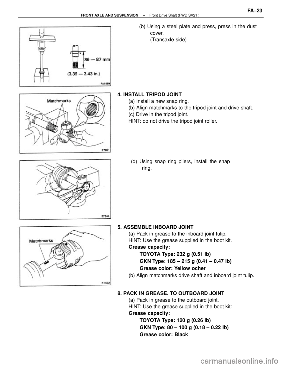
5. ASSEMBLE INBOARD JOINT
(a) Pack in grease to the inboard joint tulip.
HINT: Use the grease supplied in the boot kit.
Grease capacity:
TOYOTA Type: 232 g (0.51 Ib)
GKN Type: 185 ± 215 g (0.41 ± 0.47 Ib)
Grease color: Yellow ocher
(b) Align matchmarks drive shaft and inboard joint tulip.
8. PACK IN GREASE. TO OUTBOARD JOINT
(a) Pack in grease to the outboard joint.
HINT: Use the grease supplied in the boot kit:
Grease capacity:
TOYOTA Type: 120 g (0.26 Ib)
GKN Type: 80 ± 100 g (0.18 ± 0.22 Ib)
Grease color: Black 4. INSTALL TRIPOD JOINT
(a) Install a new snap ring.
(b) Align matchmarks to the tripod joint and drive shaft.
(c) Drive in the tripod joint.
HINT: do not drive the tripod joint roller.(b) Using a steel plate and press, press in the dust
cover.
(Transaxle side)
(d) Using snap ring pliers, install the snap
ring.
± FRONT AXLE AND SUSPENSIONFront Drive Shaft (FWD SV21 )FA±23
Trending: oil pressure, battery capacity, trailer, adding oil, seats, battery location, open hood
