TOYOTA HIGHLANDER 2001 Service Repair Manual
Manufacturer: TOYOTA, Model Year: 2001, Model line: HIGHLANDER, Model: TOYOTA HIGHLANDER 2001Pages: 2572, PDF Size: 34.8 MB
Page 321 of 2572
2005 HIGHLANDER (EWD592U)
102
ECT and A/T Indicator for 3MZ-FE
1 11 4 12 5 10 8 2 9
G- YW P- L
+B BATT20A
EF1 NO. 1
B- W W- B
L- B
Y- R
Y- B
Y- G
L- Y
L- R
G- B
G- R
23 15
2B 4 2F 4 2B 52B7
Y
R W
IK2 10 IK21110A
IGN
1G 620A
STOP
1E 1
4E 1
B BRP
I 74M 4
EH1 2
4M 124L 3
1A A3A9B1921G7. 5A
IG1
A 8
BRW
D 9D13 D11 D15 D17 D32 D 16 D 12 D14R
E 1SL1- SL1+
18 D 19 D
B- WR- B
613 IGSW STP
A
J 2MREL SR SLT+ SLT- DSL SL2+ SL2-
W- B
SL3+ SL3- THO1
S15
EFI
Relay
IK3 13
B
B
IM1 10
R
E
E
V
G
GR
SB
LG
BR
R
OL
+B2 2A
WW
P
W
B
O
3
L- W
D 10S4
Y
THO SL3- SL3+ SL1- SL1+ SL2- SL2+ DSL SLT- SLT+ S4 SR
E2
7
BR
J 6
From Power Source System (
See Page 62)
E 5(
A)
, E 6(
B)
, E 7(
E)
, E 8(
D)
, E 9(
C)
Electr onically Controlled Transmission SolenoidEngine Control Module
Junction
Connector
Junction
Connector
Stop Light SW
Page 322 of 2572
2005 HIGHLANDER (EWD592U)
103
20 IM1
W- B W- B
W- B
W- B W- B W- BBR G- BY BR
L- W
GP
Y- GG Y- R R- BL- Y
9
J 6
IM1
7C
EC ED6E 7E PL RL NL DL 2L LL
61 97382
6D 1C D7E03
W- B
W- B J 7
9B B 20 B 10 7A B 11 A 6
A
A R
BR
B- R
VC
3 5
VTA2 R
1 2
E14 E 28 E18 E19
VTA1
BR
T1 3
E 2
4 64AP 1
54K
PR ND3 2
E2 VC THW E04E1 E05 E01 E02 B
B C
C B
B7IM1 18 IM1 8IM1 19 IM1
I 6
J 6
J17Y GRL VV
L
GR
G
E 31VTA2
R- W
6E 21VTA1G
NC- NC+ NT- NT+
W- GR R- WWT 3
C 6
D 261
2
D 34 35 D 2 1
27 D B
BR
A 5B 5
E2
W- BW- B W- BG
RB
BR4CME01
W- B
I 6
W
M- 1C 2M- M+
3C
2
M+
B
GE0 1
C 17
Y
(
Shielded)
E 5(
A)
, E 6(
B)
, E 7(
E)
, E 8(
D)
, E 9(
C)
E 5(
A)
, E 6(
B)
, E 7(
E)
, E 8(
D)
, E 9(
C)
S28(
A)
, S29(
B)
Counter Gear Speed
Sensor Engine Coolant Temp.
Sensor
Engine Control Module Engine Control Module
Junction
Connector
Junction
Connector
Junction
ConnectorJunction
Connector
A/T Indicator SW
Shor t Connector
Turbine Speed Sensor
Thr ottle Position Sensor Throttle Control Motor
Page 323 of 2572
2005 HIGHLANDER (EWD592U)
104
ECT and A/T Indicator for 3MZ-FE
BMPX-
A
1MPX1
W
2IF3R
SNOW MPX1
A 16
10
GR
ODMS9
MPX2
L
GR W- B
L
W- BW- BR
MPX2
V GR Y
E 4
29 BBR
R
8B
6
IB 13 3F6
83H3
4 A17
IF3 82B A IB2 8
IB2 1
IF3 5
15
O
7
8 MPX1
MPX2
A
P 5
MPX+
W
18 B
52
BR G
B
Y
SPD
17 B
IL2 9
Y
G
83D2 B 1
A 1A2
BR
24
MPX1
BR
22
MPX2
G V
4
11MPD1
MPD2
G 5
IL2 12
SB
74F 54AG
SB
Y IL2 1
SB
IF3 12
(
*1) (
*1)
G
(
*2)
G
Y
T16
S30(
A)
, S31(
B)
A10(
A)
, A11(
B)
B 9(
A)
, B10(
B)
E 5(
A)
, E 6(
B)
, E 7(
E)
, E 8(
D)
, E 9(
C)
A/C Control Assembly Airbag Sensor Assembly
Body ECU
Electronically Controlled
Transmission Pattern Select SW
Engine Control Module
Gateway ECU Power Window Master SW
with ECUShort Connector Transmission Control SW
Transmission Shift Main SW
Page 324 of 2572
2005 HIGHLANDER (EWD592U)
105
SB
Y
13E 12 3J SBG* 1 : w/ Navigation System
* 2 : w/o Navigation System
Y21 A 9B
A/T
OI L TEM PP
ECT SNOWO/D OFFL 2 3 D N R
Y C11(
A)
, C12(
B)
Combination Meter
Page 325 of 2572
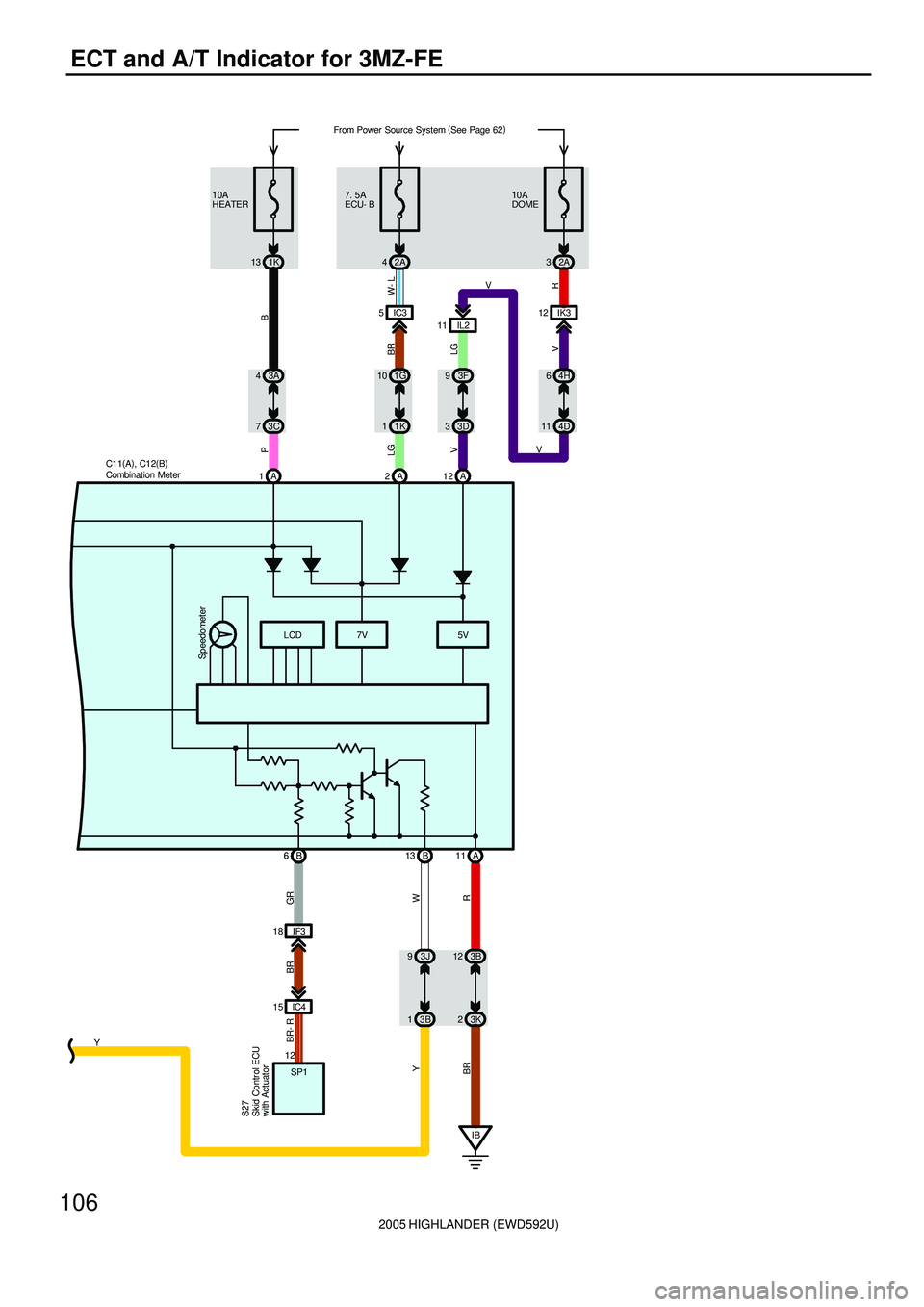
2005 HIGHLANDER (EWD592U)
106
ECT and A/T Indicator for 3MZ-FE
LCD
W Y
93J
13B IF3 18
IC4 15
GR BR BR- R
12
SP1
S27
6B
IB A 12 A 2 A
5V 7V
Speedometer
B 13 1
B 6
R
11 A
3B 12
3K 2 11 IL2IK3 12
V V
VR
32A 10A
DOME
11 4D64H
LG V
33D 93F
BR W- L LGPB
73C 43A
11K 10 1G5IC3 7. 5A
ECU- B
2A 4 13 1K 10A
HEATER
BR
YFrom Power Source System (
See Page 62)
C11(
A)
, C12(
B)
Combination Meter
Skid Contr ol ECU
with Actuator
Page 326 of 2572
2005 HIGHLANDER (EWD592U)
107
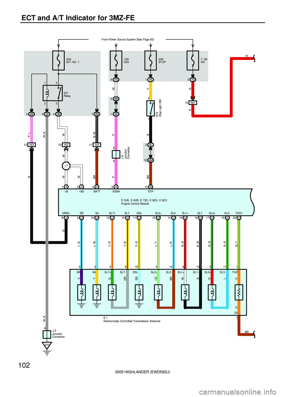
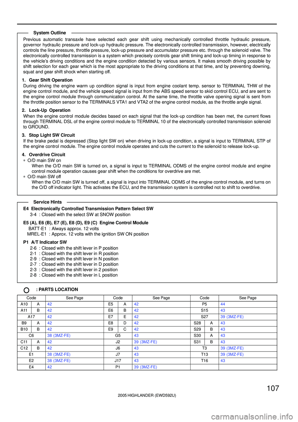
Previous automatic transaxle have selected each gear shift using mechanically controlled throttle hydraulic pressure,
governor hydraulic pressure and lock-up hydraulic pressure. The electronically controlled transmission, however, electrically
controls the line pressure, throttle pressure, lock-up pressure and accumulator pressure etc. through the solenoid valve. The
electronically controlled transmission is a system which precisely controls gear shift timing and lock-up timing in response to
the vehicle's driving conditions and the engine condition detected by various sensors. It makes smooth driving possible by
shift selection for each gear which is the most appropriate to the driving conditions at that time, and by preventing downing,
squat and gear shift shock when starting off.
1. Gear Shift Operation
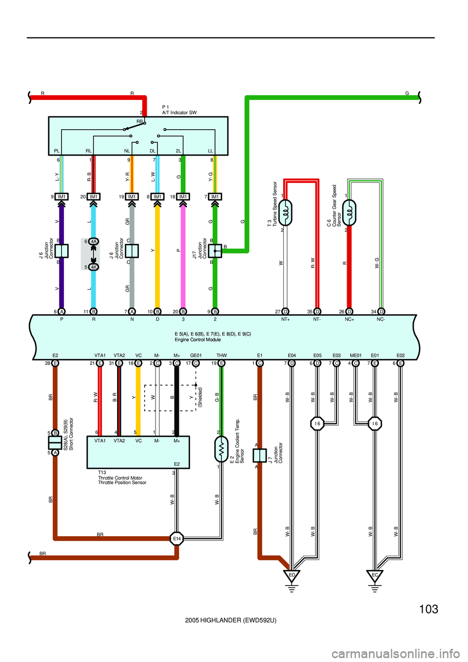
During driving the engine warm up condition signal is input from engine coolant temp. sensor to TERMINAL THW of the
engine control module, and the vehicle speed signal is input from the ABS speed sensor to skid control ECU, and are sent to
the engine control module through communication control. At the same time, the throttle valve opening signal is sent from
the throttle position sensor to the TERMINALS VTA1 and VTA2 of the engine control module, as the throttle angle signal.
2. Lock-Up Operation
When the engine control module decides based on each signal that the lock-up condition has been met, the current flows
through TERMINAL DSL of the engine control module to TERMINAL 10 of the electronically controlled transmission solenoid
to GROUND.
3. Stop Light SW Circuit
If the brake pedal is depressed (Stop light SW on) when driving in lock-up condition, a signal is input to TERMINAL STP of
the engine control module. The engine control module operates and cuts the current to the solenoid to release lock-up.
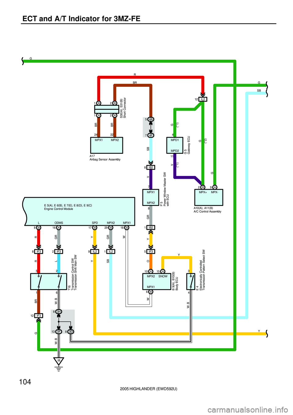
4. Overdrive Circuit
*O/D main SW on
When the O/D main SW is turned on, a signal is input to TERMINAL ODMS of the engine control module and engine
control module operation causes gear shift when the conditions for overdrive are met.
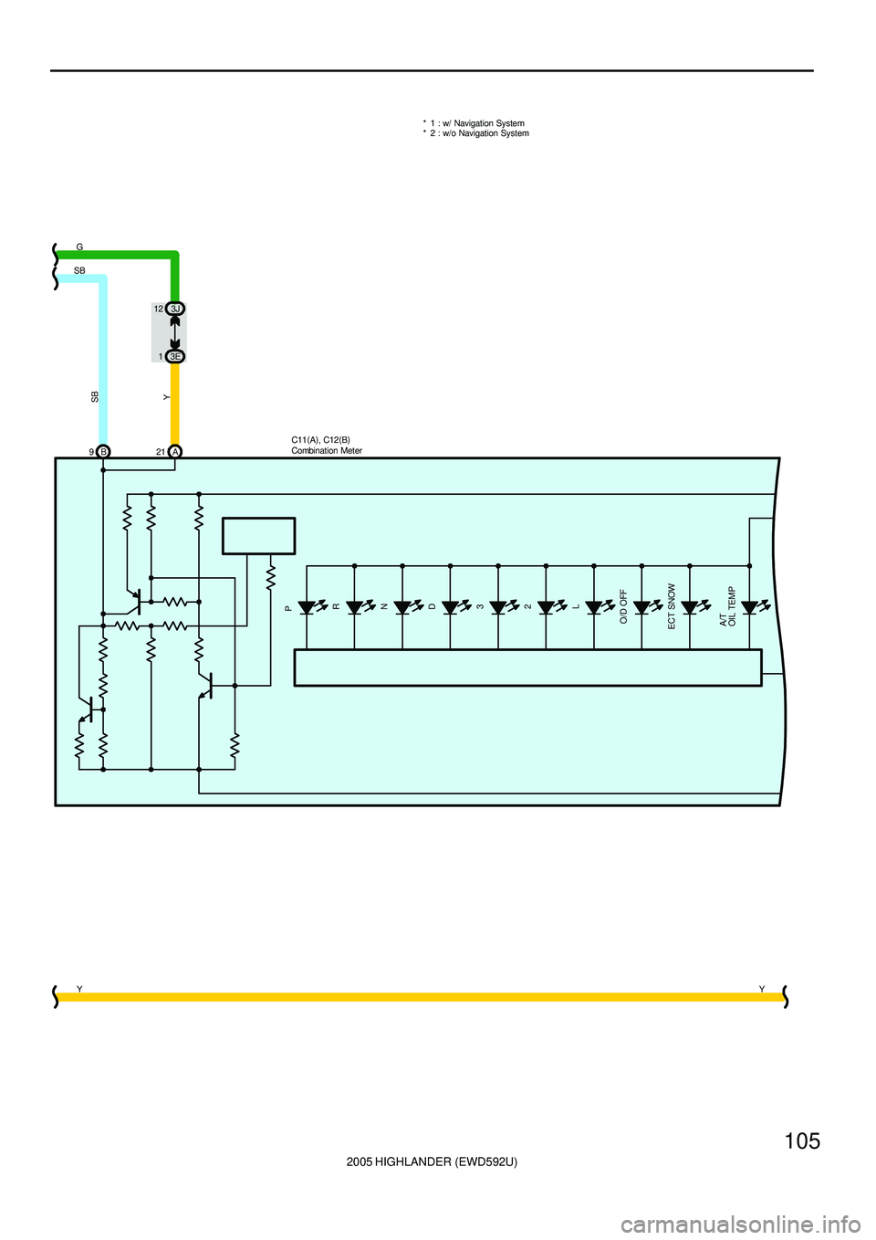
*O/D main SW off
When the O/D main SW is turned off, a signal is input into TERMINAL ODMS of the engine control module, and turns on
the O/D off indicator light. This activates the ECU, and the transmission system is controlled not to shift to overdrive.
E4 Electronically Controlled Transmission Pattern Select SW
3-4 : Closed with the select SW at SNOW position
E5 (A), E6 (B), E7 (E), E8 (D), E9 (C) Engine Control Module
BATT-E1 : Always approx. 12 volts
MREL-E1 : Approx. 12 volts with the ignition SW ON position
P1 A/T Indicator SW
2-6 : Closed with the shift lever in P position
2-1 : Closed with the shift lever in R position
2-9 : Closed with the shift lever in N position
2-7 : Closed with the shift lever in D position
2-3 : Closed with the shift lever in 2 position
2-8 : Closed with the shift lever in L position
: PARTS LOCATION
CodeSee PageCodeSee PageCodeSee Page
A10A42E5A42P544
A11B42E6B42S1543
A1742E7E42S2739 (3MZ-FE)
B9A42E8D42S28A43
B10B42E9C42S29B43
C638 (3MZ-FE)G543S30A43
C11A42J239 (3MZ-FE)S31B43
C12B42J643T339 (3MZ-FE)
E138 (3MZ-FE)J743T1339 (3MZ-FE)
E238 (3MZ-FE)J1743T1643
E442P139 (3MZ-FE)
System Outline
Service Hints
Page 327 of 2572
2005 HIGHLANDER (EWD592U)
108
ECT and A/T Indicator for 3MZ-FE
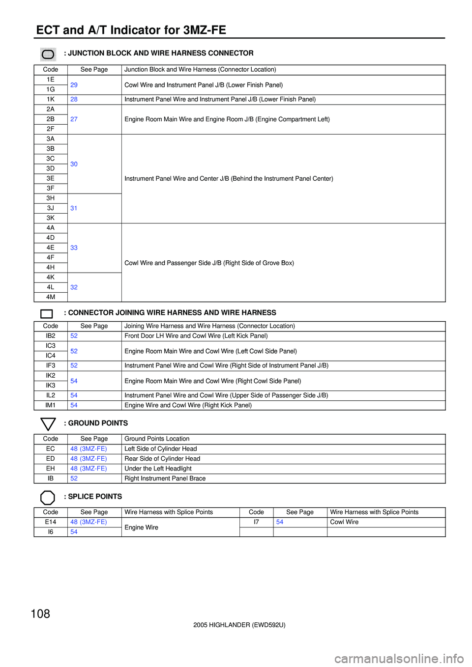
������ ���: JUNCTION BLOCK AND WIRE HARNESS CONNECTOR
CodeSee PageJunction Block and Wire Harness (Connector Location)
1E29Cowl Wire and Instrument Panel J/B (Lower Finish Panel)1G29Cowl Wire and Instrument Panel J/B (Lower Finish Panel)
1K28Instrument Panel Wire and Instrument Panel J/B (Lower Finish Panel)
2A
2B27Engine Room Main Wire and Engine Room J/B (Engine Compartment Left)
2F
gg(g)
3A
3B
3C303D30
3EInstrument Panel Wire and Center J/B (Behind the Instrument Panel Center)
3F
()
3H
3J31
3K
4A
4D
4E33
4FCowl Wire and Passenger Side J/B (Right Side of Grove Box)4HCowl Wire and Passenger Side J/B (Right Side of Grove Box)
4K
4L32
4M
: CONNECTOR JOINING WIRE HARNESS AND WIRE HARNESS
CodeSee PageJoining Wire Harness and Wire Harness (Connector Location)
IB252Front Door LH Wire and Cowl Wire (Left Kick Panel)
IC352Engine Room Main Wire and Cowl Wire (Left Cowl Side Panel)IC452Engine Room Main Wire and Cowl Wire (Left Cowl Side Panel)
IF352Instrument Panel Wire and Cowl Wire (Right Side of Instrument Panel J/B)
IK254Engine Room Main Wire and Cowl Wire (Right Cowl Side Panel)IK354Engine Room Main Wire and Cowl Wire (Right Cowl Side Panel)
IL254Instrument Panel Wire and Cowl Wire (Upper Side of Passenger Side J/B)
IM154Engine Wire and Cowl Wire (Right Kick Panel)
: GROUND POINTS
CodeSee PageGround Points Location
EC48 (3MZ-FE)Left Side of Cylinder Head
ED48 (3MZ-FE)Rear Side of Cylinder Head
EH48 (3MZ-FE)Under the Left Headlight
IB52Right Instrument Panel Brace
: SPLICE POINTS
CodeSee PageWire Harness with Splice PointsCodeSee PageWire Harness with Splice Points
E1448 (3MZ-FE)Engine WireI754Cowl Wire
I654Engine Wire
Page 328 of 2572
2005 HIGHLANDER (EWD592U)
109
MEMO
Page 329 of 2572
'05 HIGHLANDER_U (L/O 0409)
169
2005 HIGHLANDER from Nov. '04 Prod. (OM48570U)
OPERATION OF INSTRUMENTS AND
CONTROLS
Audio system
Reference170 . . . . . . . . . . . . . . . . . . . . . . . . . . . . . . . . . . . . . . . . . . . . . . . . .
Using your audio system170 . . . . . . . . . . . . . . . . . . . . . . . . . . . . . . . . . . . .
Audio remote controls186 . . . . . . . . . . . . . . . . . . . . . . . . . . . . . . . . . . . . . . .
Rear seat entertainment system189 . . . . . . . . . . . . . . . . . . . . . . . . . . . . . .
Audio/video system operating hints240 . . . . . . . . . . . . . . . . . . . . . . . . . . .
For vehicle equipped with Navigation system, please refer to the
separate Navigation System Owner's Manualº.
SECTION 1- 8
Page 330 of 2572
'05 HIGHLANDER_U (L/O 0409)
170
2005 HIGHLANDER from Nov. '04 Prod. (OM48570U)
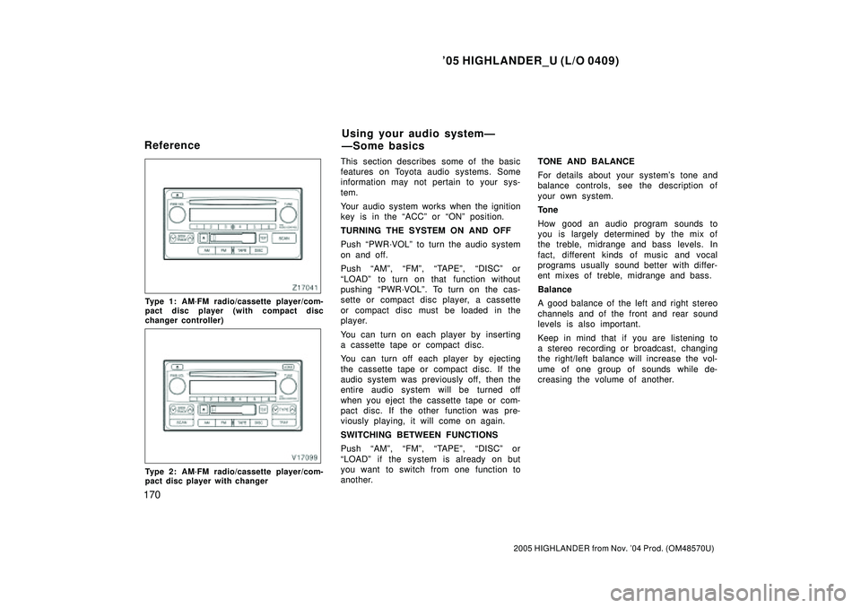
Type 1: AM´FM radio/cassette player/com-
pact disc player (with compact disc
changer controller)
Type 2: AM´FM radio/cassette player/com-
pact disc player with changer
This section describes some of the basic
features on Toyota audio systems. Some
information may not pertain to your sys-
tem.
Your audio system works when the ignition
key is in the ACCº or ONº position.
TURNING THE SYSTEM ON AND OFF
Push PWR´VOLº to turn the audio system
on and off.
Push AMº, FMº, TAPEº, DISCº or
LOADº to turn on that function without
pushing PWR´VOLº. To turn on the cas-
sette or compact disc player, a cassette
or compact disc must be loaded in the
player.
You can turn on each player by inserting
a cassette tape or compact disc.
You can turn off each player by ejecting
the cassette tape or compact disc. If the
audio system was previously off, then the
entire audio system will be turned off
when you eject the cassette tape or com-
pact disc. If the other function was pre-
viously playing, it will come on again.
SWITCHING BETWEEN FUNCTIONS
Push AMº, FMº, TAPEº, DISCº or
LOADº if the system is already on but
you want to switch from one function to
another.TONE AND BALANCE
For details about your system's tone and
balance controls, see the description of
your own system.
Tone
How good an audio program sounds to
you is largely determined by the mix of
the treble, midrange and bass levels. In
fact, different kinds of music and vocal
programs usually sound better with differ-
ent mixes of treble, midrange and bass.
Balance
A good balance of the left and right stereo
channels and of the front and rear sound
levels is also important.
Keep in mind that if you are listening to
a stereo recording or broadcast, changing
the right/left balance will increase the vol-
ume of one group of sounds while de-
creasing the volume of another.
ReferenceUsing your audio systemÐ
ÐSome basics