TOYOTA RAV4 1996 Service Repair Manual
Manufacturer: TOYOTA, Model Year: 1996, Model line: RAV4, Model: TOYOTA RAV4 1996Pages: 1632, PDF Size: 41.64 MB
Page 1151 of 1632
2. Using a floor jack, support suspension member. Remove suspension member nuts, bolts and stoppers.
Lower suspension member. Remove No. 1 lower suspension arm.
Installation
1. To install, reverse removal procedure. Be sure to install components in their original locations. On all
models except Corolla, suspension arms are marked with paint. Install suspension arms with paint marks
facing rearward. On Corolla models, suspension arms have left hand threads on one side. Install
suspension arms with left hand threads to the axle carrier side.
2. Install all nuts and bolts, but DO NOT tighten. Install wheels. Lower vehicle. Bounce vehicle several
times to stabilize suspension. Tighten all nuts and bolts to specification, with vehicle weight on
suspension. See TORQUE SPECIFICATIONS
. Check rear wheel alignment. See SPECIFICATIONS
& PROCEDURES article in WHEEL ALIGNMENT.
WHEEL BEARINGS (HUBS)
Removal (Avalon, Camry, Camry Solara, Celica, Corolla & RAV4 FWD)
1. Raise and support vehicle. Remove rear wheels. On drum brake models, remove brake drum. On disc
brake models, remove rotor. Remove caliper, leaving flex hose attached, suspend aside. Disconnect ABS
sensor (if equipped).
2. On all models, check wheel hub axial play and runout. See WHEEL BEARING INSPECTION
under
ADJUSTMENTS & INSPECTION. Remove 4 bolts and remove axle hub and "O" ring.
Installation
Coat NEW "O" ring with grease and install hub. To complete installation, reverse removal procedure. Tighten
all nuts and bolts to specification. See TORQUE SPECIFICATIONS
.
Removal (RAV4 4WD)
1. Raise and support vehicle. Remove rear wheel and brake drum. Using a dial indicator, check wheel
bearing end play and runout. End play should not exceed .002" (.05 mm). Runout should not
exceed .0028" (.07 mm). If axle hub end play or runout exceed specification, replace hub with bearing.
2. Remove bolt and ABS sensor. Remove drive axle. Remove drive axle lock nut. Place matchmarks on
drive axle and differential side gear shaft. Remove 4 nuts and remove drive axle. Disassemble rear brake
shoes. Disconnect brakeline from wheel cylinder. Remove parking brake cable. Remove 4 bolts and
remove axle hub with bearing and backing plate. See Fig. 10
.
3. Using Puller (09950-40011) and Replacer Set (09950-60011), remove bearing from axle hub. Remove
bearing race from axle hub. See Fig. 11. NOTE: Wheel bearings and wheel hub, is a one piece assembly and must be replaced
as a single unit.
1999 Toyota RAV4
1999-2000 SUSPENSION Rear - Front Wheel Drive
Microsoft
Sunday, November 22, 2009 10:37:21 AMPage 13 © 2005 Mitchell Repair Information Company, LLC.
Page 1152 of 1632
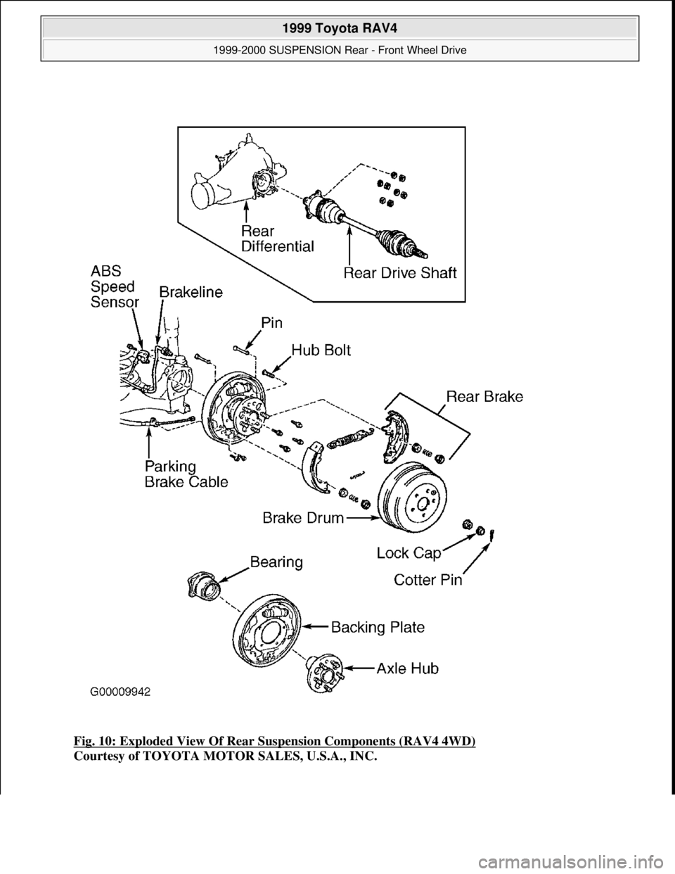
Fig. 10: Exploded View Of Rear Suspension Components (RAV4 4WD)
Courtesy of TOYOTA MOTOR SALES, U.S.A., INC.
1999 Toyota RAV4
1999-2000 SUSPENSION Rear - Front Wheel Drive
Microsoft
Sunday, November 22, 2009 10:37:21 AMPage 14 © 2005 Mitchell Repair Information Company, LLC.
Page 1153 of 1632
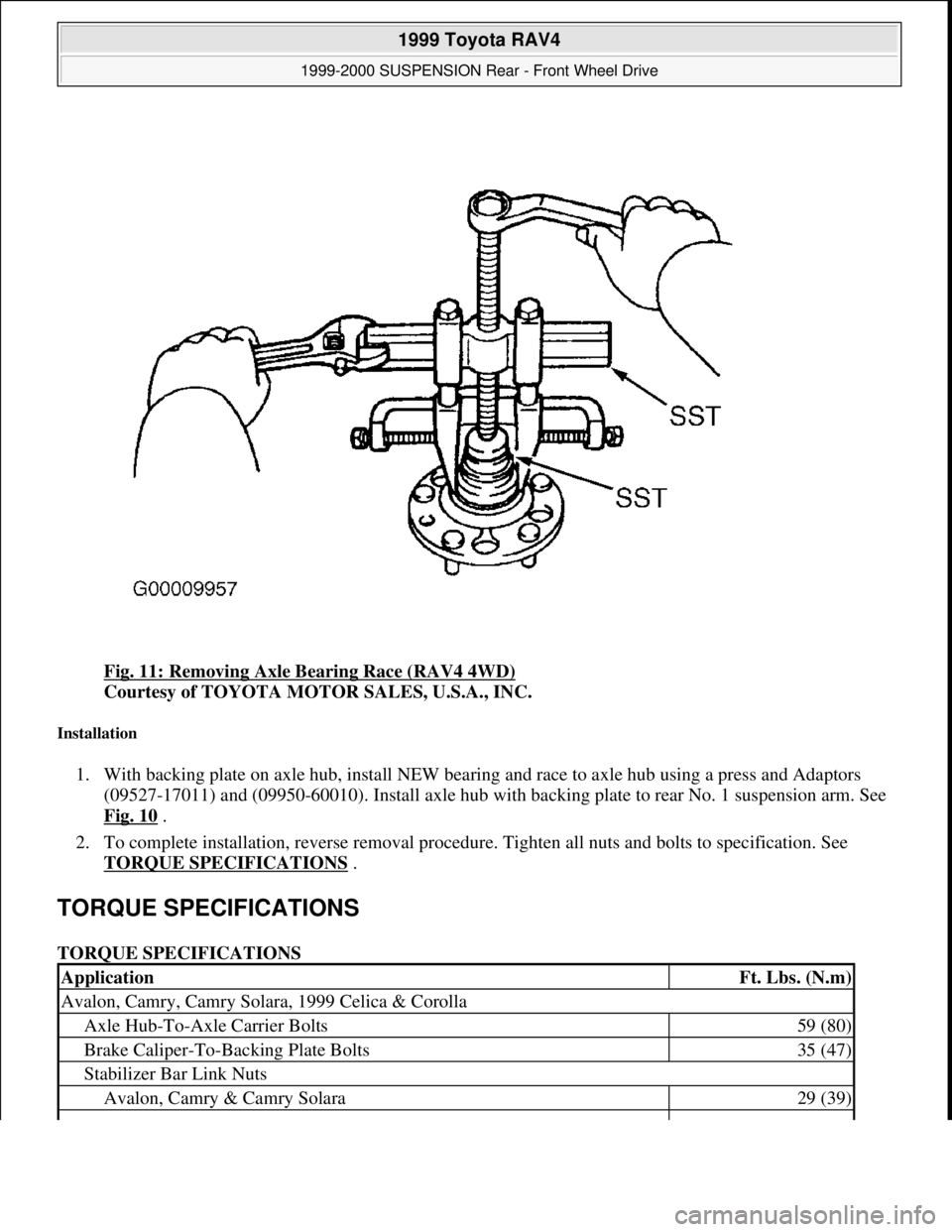
Fig. 11: Removing Axle Bearing Race (RAV4 4WD)
Courtesy of TOYOTA MOTOR SALES, U.S.A., INC.
Installation
1. With backing plate on axle hub, install NEW bearing and race to axle hub using a press and Adaptors
(09527-17011) and (09950-60010). Install axle hub with backing plate to rear No. 1 suspension arm. See
Fig. 10
.
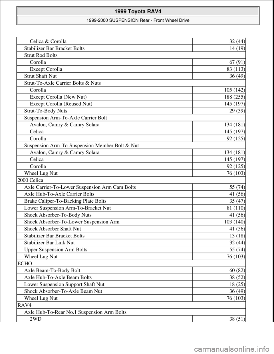
2. To complete installation, reverse removal procedure. Tighten all nuts and bolts to specification. See
TORQUE SPECIFICATIONS
.
TORQUE SPECIFICATIONS
TORQUE SPECIFICATIONS
ApplicationFt. Lbs. (N.m)
Avalon, Camry, Camry Solara, 1999 Celica & Corolla
Axle Hub-To-Axle Carrier Bolts59 (80)
Brake Caliper-To-Backing Plate Bolts35 (47)
Stabilizer Bar Link Nuts
Avalon, Camry & Camry Solara29 (39)
1999 Toyota RAV4
1999-2000 SUSPENSION Rear - Front Wheel Drive
Microsoft
Sunday, November 22, 2009 10:37:21 AMPage 15 © 2005 Mitchell Repair Information Company, LLC.
Page 1154 of 1632
Celica & Corolla32 (44)
Stabilizer Bar Bracket Bolts14 (19)
Strut Rod Bolts
Corolla67 (91)
Except Corolla83 (113)
Strut Shaft Nut36 (49)
Strut-To-Axle Carrier Bolts & Nuts
Corolla105 (142)
Except Corolla (New Nut)188 (255)
Except Corolla (Reused Nut)145 (197)
Strut-To-Body Nuts29 (39)
Suspension Arm-To-Axle Carrier Bolt
Avalon, Camry & Camry Solara134 (181)
Celica145 (197)
Corolla92 (125)
Suspension Arm-To-Suspension Member Bolt & Nut
Avalon, Camry & Camry Solara134 (181)
Celica145 (197)
Corolla92 (125)
Wheel Lug Nut76 (103)
2000 Celica
Axle Carrier-To-Lower Suspension Arm Cam Bolts55 (74)
Axle Hub-To-Axle Carrier Bolts41 (56)
Brake Caliper-To-Backing Plate Bolts35 (47)
Lower Suspension Arm-To-Bracket Nut81 (110)
Shock Absorber-To-Body Nuts41 (56)
Shock Absorber-To-Lower Suspension Arm103 (140)
Shock Absorber Shaft Nut41 (56)
Stabilizer Bar Bracket Bolts13 (18)
Stabilizer Bar Link Nut32 (44)
Upper Suspension Arm Bolts55 (74)
Wheel Lug Nut76 (103)
ECHO
Axle Beam-To-Body Bolt60 (82)
Axle Hub-To-Axle Beam Bolts38 (52)
Lower Suspension Support Shaft Nut18 (25)
Shock Absorber-To-Axle Beam Nut36 (49)
Wheel Lug Nut76 (103)
RAV4
Axle Hub-To-Rear No.1 Suspension Arm Bolts
2WD38 (51)
1999 Toyota RAV4
1999-2000 SUSPENSION Rear - Front Wheel Drive
Microsoft
Sunday, November 22, 2009 10:37:21 AMPage 16 © 2005 Mitchell Repair Information Company, LLC.
Page 1155 of 1632
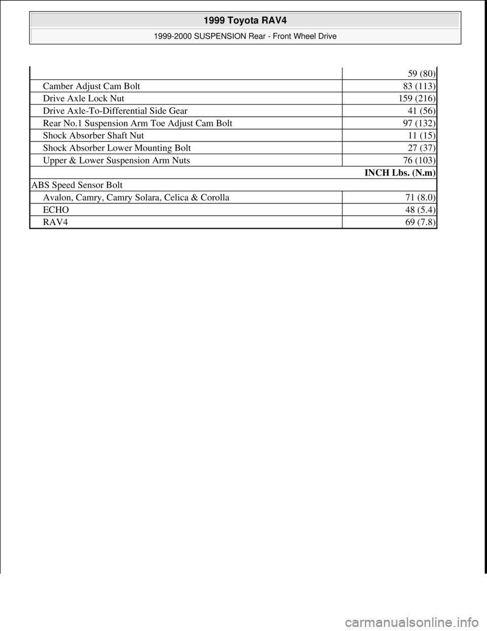
59 (80)
Camber Adjust Cam Bolt83 (113)
Drive Axle Lock Nut159 (216)
Drive Axle-To-Differential Side Gear41 (56)
Rear No.1 Suspension Arm Toe Adjust Cam Bolt97 (132)
Shock Absorber Shaft Nut11 (15)
Shock Absorber Lower Mounting Bolt27 (37)
Upper & Lower Suspension Arm Nuts76 (103)
INCH Lbs. (N.m)
ABS Speed Sensor Bolt
Avalon, Camry, Camry Solara, Celica & Corolla71 (8.0)
ECHO48 (5.4)
RAV469 (7.8)
1999 Toyota RAV4
1999-2000 SUSPENSION Rear - Front Wheel Drive
Microsoft
Sunday, November 22, 2009 10:37:21 AMPage 17 © 2005 Mitchell Repair Information Company, LLC.
Page 1156 of 1632
1999-2000 STARTING & CHARGING SYSTEMS
Starters
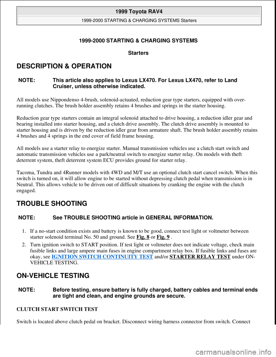
DESCRIPTION & OPERATION
All models use Nippondenso 4-brush, solenoid-actuated, reduction gear type starters, equipped with over-
running clutches. The brush holder assembly retains 4 brushes and springs in the starter housing.
Reduction gear type starters contain an integral solenoid attached to drive housing, a reduction idler gear and
bearing installed into starter housing, and a clutch drive assembly. The clutch drive assembly is mounted to
starter housing and is driven by the reduction idler gear from armature shaft. The brush holder assembly retains
4 brushes and 4 springs in the end cover of field frame housing.
All models use a starter relay to energize starter. Manual transmission vehicles use a clutch start switch and
automatic transmission vehicles use a park/neutral switch to energize starter relay. On models with theft
deterrent system, theft deterrent system ECU provides ground for starter relay.
Tacoma, Tundra and 4Runner models with 4WD and M/T use an optional clutch start cancel switch. When this
switch is turned on, it will allow engine to be started without depressing clutch pedal when transmission is in
Neutral. This allows vehicle to be driven out of difficult situations by cranking the engine with the clutch
engaged.
TROUBLE SHOOTING
1. If a no-start condition exists and battery is known to be good, connect test light or voltmeter between
starter solenoid terminal No. 50 and ground. See Fig. 8
or Fig. 9 .
2. Turn ignition switch to START position. If test light or voltmeter does not indicate voltage, check main
fusible links and large ampere main fuses in engine compartment relay box. If fusible links and fuses are
okay, see IGNITION SWITCH CONTINUITY TEST
and/or STARTER RELAY TEST under ON-
VEHICLE TESTING.
ON-VEHICLE TESTING
CLUTCH START SWITCH TEST
Switch is located above clutch pedal on bracket. Disconnect wirin
g harness connector from switch. Connect NOTE: This article also applies to Lexus LX470. For Lexus LX470, refer to Land
Cruiser, unless otherwise indicated.
NOTE: See TROUBLE SHOOTING article in GENERAL INFORMATION.
NOTE: Before testing, ensure battery is fully charged, battery cables and terminal ends
are tight and clean, and engine grounds are secure.
1999 Toyota RAV4
1999-2000 STARTING & CHARGING SYSTEMS Starters
1999 Toyota RAV4
1999-2000 STARTING & CHARGING SYSTEMS Starters
Microsoft
Sunday, November 22, 2009 10:19:17 AMPage 1 © 2005 Mitchell Repair Information Company, LLC.
Microsoft
Sunday, November 22, 2009 10:19:23 AMPage 1 © 2005 Mitchell Repair Information Company, LLC.
Page 1157 of 1632
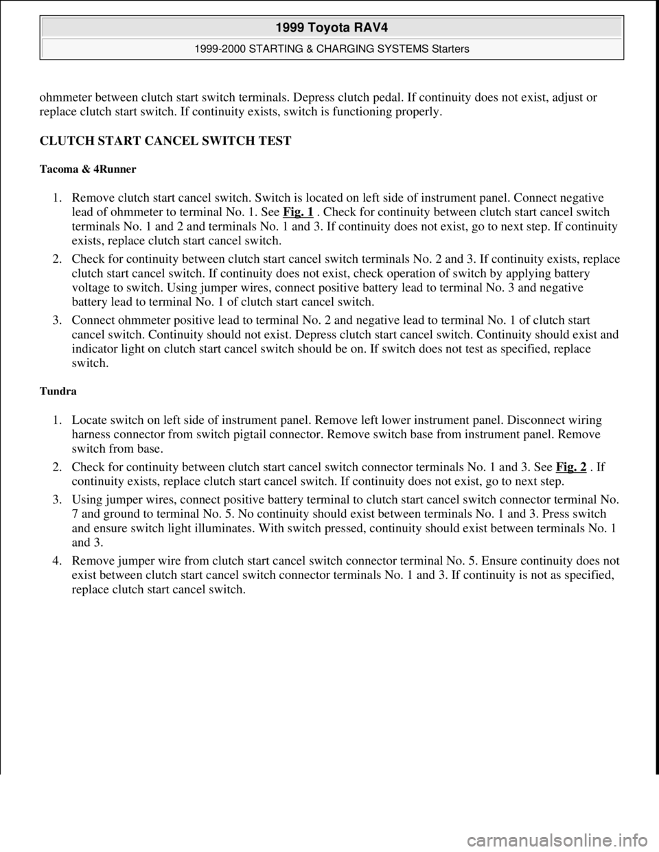
ohmmeter between clutch start switch terminals. Depress clutch pedal. If continuity does not exist, adjust or
replace clutch start switch. If continuity exists, switch is functioning properly.
CLUTCH START CANCEL SWITCH TEST
Tacoma & 4Runner
1. Remove clutch start cancel switch. Switch is located on left side of instrument panel. Connect negative
lead of ohmmeter to terminal No. 1. See Fig. 1
. Check for continuity between clutch start cancel switch
terminals No. 1 and 2 and terminals No. 1 and 3. If continuity does not exist, go to next step. If continuity
exists, replace clutch start cancel switch.
2. Check for continuity between clutch start cancel switch terminals No. 2 and 3. If continuity exists, replace
clutch start cancel switch. If continuity does not exist, check operation of switch by applying battery
voltage to switch. Using jumper wires, connect positive battery lead to terminal No. 3 and negative
battery lead to terminal No. 1 of clutch start cancel switch.
3. Connect ohmmeter positive lead to terminal No. 2 and negative lead to terminal No. 1 of clutch start
cancel switch. Continuity should not exist. Depress clutch start cancel switch. Continuity should exist and
indicator light on clutch start cancel switch should be on. If switch does not test as specified, replace
switch.
Tundra
1. Locate switch on left side of instrument panel. Remove left lower instrument panel. Disconnect wiring
harness connector from switch pigtail connector. Remove switch base from instrument panel. Remove
switch from base.
2. Check for continuity between clutch start cancel switch connector terminals No. 1 and 3. See Fig. 2
. If
continuity exists, replace clutch start cancel switch. If continuity does not exist, go to next step.
3. Using jumper wires, connect positive battery terminal to clutch start cancel switch connector terminal No.
7 and ground to terminal No. 5. No continuity should exist between terminals No. 1 and 3. Press switch
and ensure switch light illuminates. With switch pressed, continuity should exist between terminals No. 1
and 3.
4. Remove jumper wire from clutch start cancel switch connector terminal No. 5. Ensure continuity does not
exist between clutch start cancel switch connector terminals No. 1 and 3. If continuity is not as specified,
replace clutch start cancel switch.
1999 Toyota RAV4
1999-2000 STARTING & CHARGING SYSTEMS Starters
Microsoft
Sunday, November 22, 2009 10:19:18 AMPage 2 © 2005 Mitchell Repair Information Company, LLC.
Page 1158 of 1632
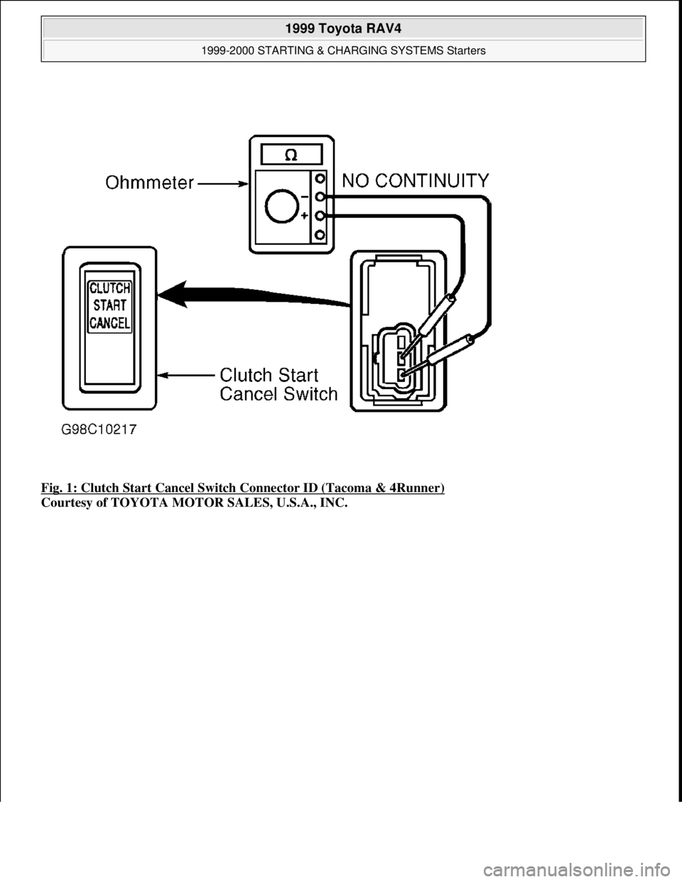
Fig. 1: Clutch Start Cancel Switch Connector ID (Tacoma & 4Runner)
Courtesy of TOYOTA MOTOR SALES, U.S.A., INC.
1999 Toyota RAV4
1999-2000 STARTING & CHARGING SYSTEMS Starters
Microsoft
Sunday, November 22, 2009 10:19:18 AMPage 3 © 2005 Mitchell Repair Information Company, LLC.
Page 1159 of 1632
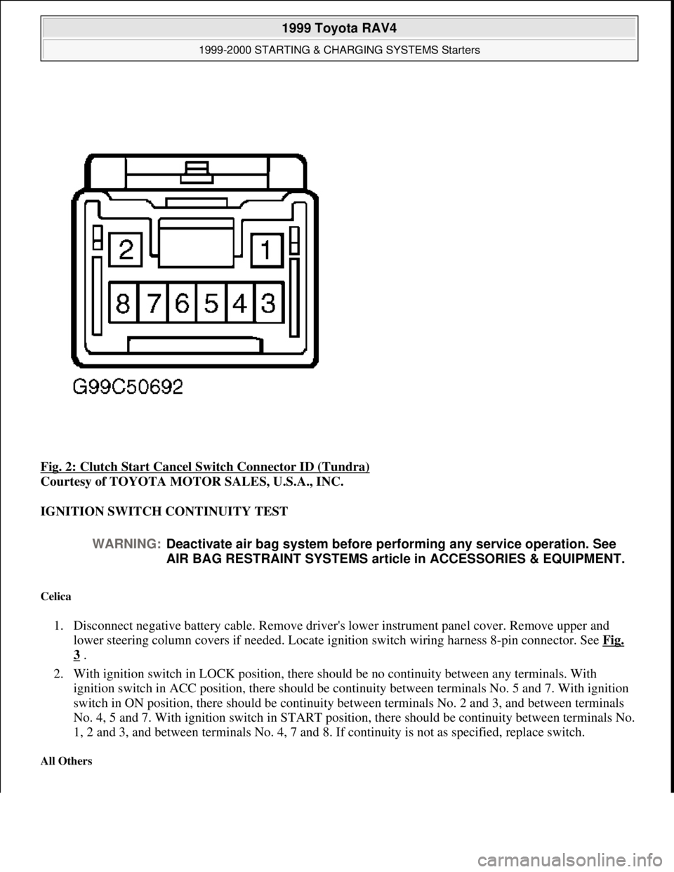
Fig. 2: Clutch Start Cancel Switch Connector ID (Tundra)
Courtesy of TOYOTA MOTOR SALES, U.S.A., INC.
IGNITION SWITCH CONTINUITY TEST
Celica
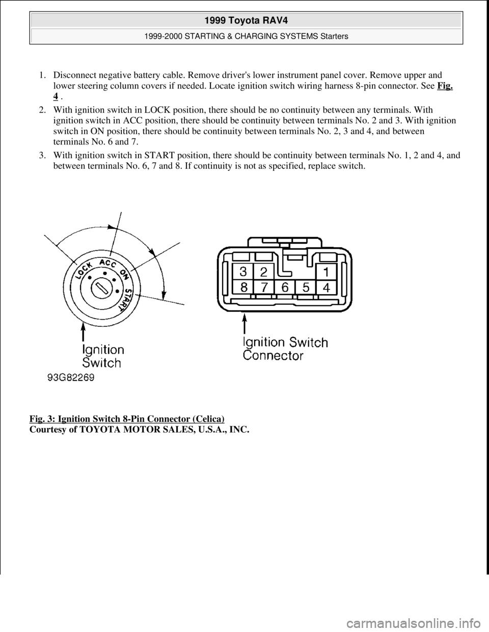
1. Disconnect negative battery cable. Remove driver's lower instrument panel cover. Remove upper and
lower steering column covers if needed. Locate ignition switch wiring harness 8-pin connector. See Fig.
3 .
2. With ignition switch in LOCK position, there should be no continuity between any terminals. With
ignition switch in ACC position, there should be continuity between terminals No. 5 and 7. With ignition
switch in ON position, there should be continuity between terminals No. 2 and 3, and between terminals
No. 4, 5 and 7. With ignition switch in START position, there should be continuity between terminals No.
1, 2 and 3, and between terminals No. 4, 7 and 8. If continuity is not as specified, replace switch.
All Others
WARNING:Deactivate air bag system before performing any service operation. See
AIR BAG RESTRAINT SYSTEMS article in ACCESSORIES & EQUIPMENT.
1999 Toyota RAV4
1999-2000 STARTING & CHARGING SYSTEMS Starters
Microsoft
Sunday, November 22, 2009 10:19:18 AMPage 4 © 2005 Mitchell Repair Information Company, LLC.
Page 1160 of 1632
1. Disconnect negative battery cable. Remove driver's lower instrument panel cover. Remove upper and
lower steering column covers if needed. Locate ignition switch wiring harness 8-pin connector. See Fig.
4 .
2. With ignition switch in LOCK position, there should be no continuity between any terminals. With
ignition switch in ACC position, there should be continuity between terminals No. 2 and 3. With ignition
switch in ON position, there should be continuity between terminals No. 2, 3 and 4, and between
terminals No. 6 and 7.
3. With ignition switch in START position, there should be continuity between terminals No. 1, 2 and 4, and
between terminals No. 6, 7 and 8. If continuity is not as specified, replace switch.
Fig. 3: Ignition Switch 8
-Pin Connector (Celica)
Courtesy of TOYOTA MOTOR SALES, U.S.A., INC.
1999 Toyota RAV4
1999-2000 STARTING & CHARGING SYSTEMS Starters
Microsoft
Sunday, November 22, 2009 10:19:18 AMPage 5 © 2005 Mitchell Repair Information Company, LLC.