TOYOTA RAV4 2006 Service Repair Manual
Manufacturer: TOYOTA, Model Year: 2006, Model line: RAV4, Model: TOYOTA RAV4 2006Pages: 2000, PDF Size: 45.84 MB
Page 1081 of 2000
U151E AUTOMATIC TRANSAXLE – AUTOMATIC TRANSAXLE UNITAX–207
AX
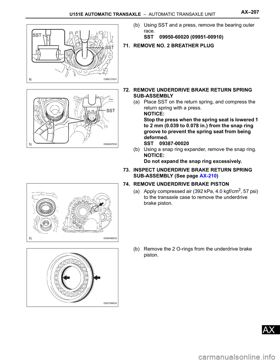
(b) Using SST and a press, remove the bearing outer
race.
SST 09950-60020 (09951-00910)
71. REMOVE NO. 2 BREATHER PLUG
72. REMOVE UNDERDRIVE BRAKE RETURN SPRING
SUB-ASSEMBLY
(a) Place SST on the return spring, and compress the
return spring with a press.
NOTICE:
Stop the press when the spring seat is lowered 1
to 2 mm (0.039 to 0.078 in.) from the snap ring
groove to prevent the spring seat from being
deformed.
SST 09387-00020
(b) Using a snap ring expander, remove the snap ring.
NOTICE:
Do not expand the snap ring excessively.
73. INSPECT UNDERDRIVE BRAKE RETURN SPRING
SUB-ASSEMBLY (See page AX-210)
74. REMOVE UNDERDRIVE BRAKE PISTON
(a) Apply compressed air (392 kPa, 4.0 kgf/cm
2, 57 psi)
to the transaxle case to remove the underdrive
brake piston.
(b) Remove the 2 O-rings from the underdrive brake
piston.
C089121E01
D026407E02
D026406E03
D003794E02
Page 1082 of 2000
AX–208U151E AUTOMATIC TRANSAXLE – AUTOMATIC TRANSAXLE UNIT
AX
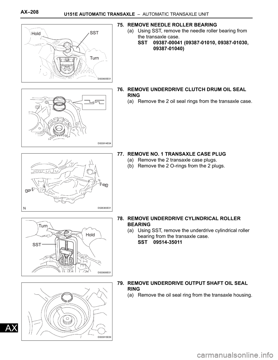
75. REMOVE NEEDLE ROLLER BEARING
(a) Using SST, remove the needle roller bearing from
the transaxle case.
SST 09387-00041 (09387-01010, 09387-01030,
09387-01040)
76. REMOVE UNDERDRIVE CLUTCH DRUM OIL SEAL
RING
(a) Remove the 2 oil seal rings from the transaxle case.
77. REMOVE NO. 1 TRANSAXLE CASE PLUG
(a) Remove the 2 transaxle case plugs.
(b) Remove the 2 O-rings from the 2 plugs.
78. REMOVE UNDERDRIVE CYLINDRICAL ROLLER
BEARING
(a) Using SST, remove the underdrive cylindrical roller
bearing from the transaxle case.
SST 09514-35011
79. REMOVE UNDERDRIVE OUTPUT SHAFT OIL SEAL
RING
(a) Remove the oil seal ring from the transaxle housing.
D003605E01
D003914E04
D026383E01
D003606E01
D003915E09
Page 1083 of 2000
U151E AUTOMATIC TRANSAXLE – AUTOMATIC TRANSAXLE UNITAX–209
AX
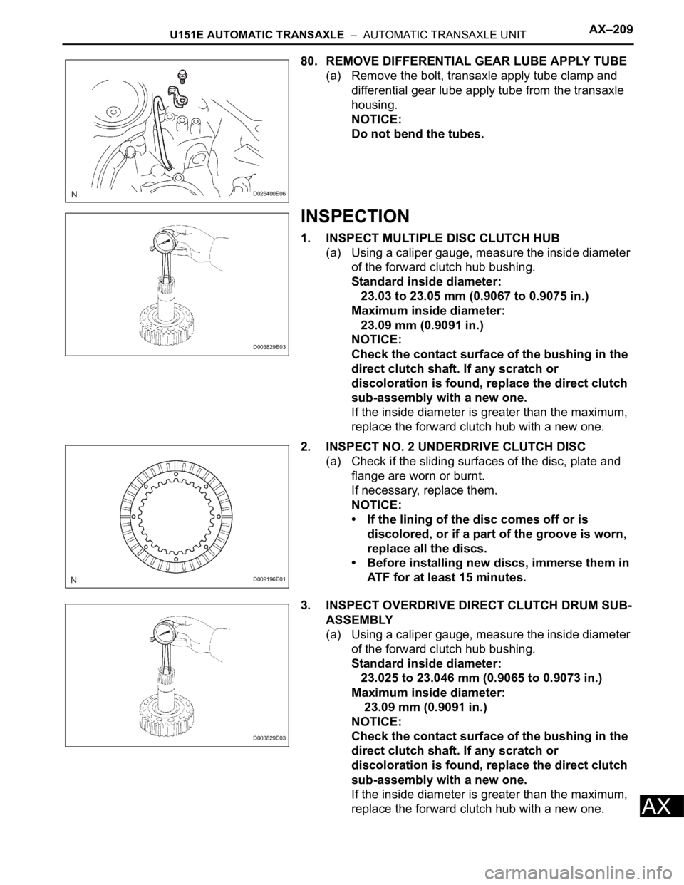
80. REMOVE DIFFERENTIAL GEAR LUBE APPLY TUBE
(a) Remove the bolt, transaxle apply tube clamp and
differential gear lube apply tube from the transaxle
housing.
NOTICE:
Do not bend the tubes.
INSPECTION
1. INSPECT MULTIPLE DISC CLUTCH HUB
(a) Using a caliper gauge, measure the inside diameter
of the forward clutch hub bushing.
Standard inside diameter:
23.03 to 23.05 mm (0.9067 to 0.9075 in.)
Maximum inside diameter:
23.09 mm (0.9091 in.)
NOTICE:
Check the contact surface of the bushing in the
direct clutch shaft. If any scratch or
discoloration is found, replace the direct clutch
sub-assembly with a new one.
If the inside diameter is greater than the maximum,
replace the forward clutch hub with a new one.
2. INSPECT NO. 2 UNDERDRIVE CLUTCH DISC
(a) Check if the sliding surfaces of the disc, plate and
flange are worn or burnt.
If necessary, replace them.
NOTICE:
• If the lining of the disc comes off or is
discolored, or if a part of the groove is worn,
replace all the discs.
• Before installing new discs, immerse them in
ATF for at least 15 minutes.
3. INSPECT OVERDRIVE DIRECT CLUTCH DRUM SUB-
ASSEMBLY
(a) Using a caliper gauge, measure the inside diameter
of the forward clutch hub bushing.
Standard inside diameter:
23.025 to 23.046 mm (0.9065 to 0.9073 in.)
Maximum inside diameter:
23.09 mm (0.9091 in.)
NOTICE:
Check the contact surface of the bushing in the
direct clutch shaft. If any scratch or
discoloration is found, replace the direct clutch
sub-assembly with a new one.
If the inside diameter is greater than the maximum,
replace the forward clutch hub with a new one.
D026400E06
D003829E03
D009196E01
D003829E03
Page 1084 of 2000
AX–210U151E AUTOMATIC TRANSAXLE – AUTOMATIC TRANSAXLE UNIT
AX
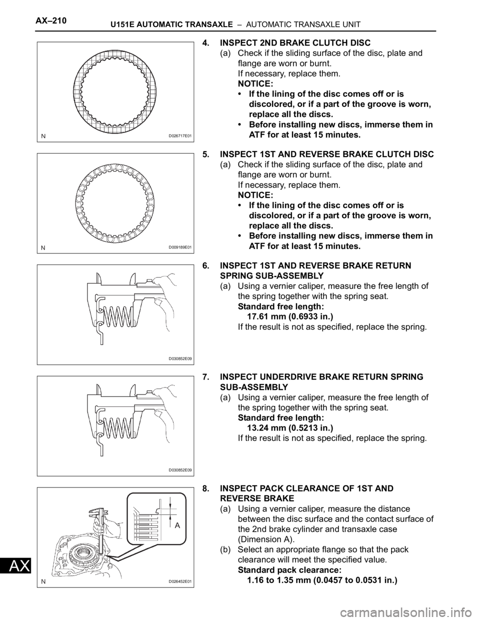
4. INSPECT 2ND BRAKE CLUTCH DISC
(a) Check if the sliding surface of the disc, plate and
flange are worn or burnt.
If necessary, replace them.
NOTICE:
• If the lining of the disc comes off or is
discolored, or if a part of the groove is worn,
replace all the discs.
• Before installing new discs, immerse them in
ATF for at least 15 minutes.
5. INSPECT 1ST AND REVERSE BRAKE CLUTCH DISC
(a) Check if the sliding surface of the disc, plate and
flange are worn or burnt.
If necessary, replace them.
NOTICE:
• If the lining of the disc comes off or is
discolored, or if a part of the groove is worn,
replace all the discs.
• Before installing new discs, immerse them in
ATF for at least 15 minutes.
6. INSPECT 1ST AND REVERSE BRAKE RETURN
SPRING SUB-ASSEMBLY
(a) Using a vernier caliper, measure the free length of
the spring together with the spring seat.
Standard free length:
17.61 mm (0.6933 in.)
If the result is not as specified, replace the spring.
7. INSPECT UNDERDRIVE BRAKE RETURN SPRING
SUB-ASSEMBLY
(a) Using a vernier caliper, measure the free length of
the spring together with the spring seat.
Standard free length:
13.24 mm (0.5213 in.)
If the result is not as specified, replace the spring.
8. INSPECT PACK CLEARANCE OF 1ST AND
REVERSE BRAKE
(a) Using a vernier caliper, measure the distance
between the disc surface and the contact surface of
the 2nd brake cylinder and transaxle case
(Dimension A).
(b) Select an appropriate flange so that the pack
clearance will meet the specified value.
Standard pack clearance:
1.16 to 1.35 mm (0.0457 to 0.0531 in.)
D026717E01
D009189E01
D030852E09
D030852E09
D026452E01
Page 1085 of 2000
U151E AUTOMATIC TRANSAXLE – AUTOMATIC TRANSAXLE UNITAX–211
AX
HINT:
Piston stroke = Dimension A - Flange thickness
Standard flange thickness
9. INSPECT PACK CLEARANCE OF 2ND BRAKE
(a) Using a vernier caliper, measure the distance
between the disc surface and snap ring surface
(Dimension B).
(b) Select an appropriate flange so that the pack
clearance will meet the specified value.
Standard pack clearance:
0.62 to 0.91 mm (0.0244 to 0.0358 in.)
HINT:
Piston stroke = Dimension B - Flange thickness -
Snap ring thickness 1.6 mm (0.063 in.)
Standard flange thickness
10. INSPECT PACK CLEARANCE OF UNDERDRIVE
BRAKE
(a) Using a dial indicator, measure the underdrive brake
pack clearance while applying and releasing
compressed air (392 kPa, 4.0 kgf/cm
2, 57 psi).
Standard pack clearance:
1.81 to 2.20 mm (0.0713 to 0.0866 in.)
HINT:
Select an appropriate flange from the table below so
that it will meet the specified value.
Standard flange thickness
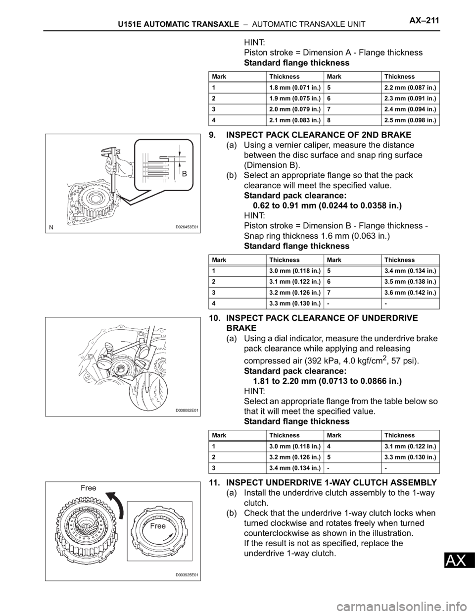
11. INSPECT UNDERDRIVE 1-WAY CLUTCH ASSEMBLY
(a) Install the underdrive clutch assembly to the 1-way
clutch.
(b) Check that the underdrive 1-way clutch locks when
turned clockwise and rotates freely when turned
counterclockwise as shown in the illustration.
If the result is not as specified, replace the
underdrive 1-way clutch.
Mark Thickness Mark Thickness
1 1.8 mm (0.071 in.) 5 2.2 mm (0.087 in.)
2 1.9 mm (0.075 in.) 6 2.3 mm (0.091 in.)
3 2.0 mm (0.079 in.) 7 2.4 mm (0.094 in.)
4 2.1 mm (0.083 in.) 8 2.5 mm (0.098 in.)
D026453E01
Mark Thickness Mark Thickness
1 3.0 mm (0.118 in.) 5 3.4 mm (0.134 in.)
2 3.1 mm (0.122 in.) 6 3.5 mm (0.138 in.)
3 3.2 mm (0.126 in.) 7 3.6 mm (0.142 in.)
4 3.3 mm (0.130 in.) - -
D008082E01
Mark Thickness Mark Thickness
1 3.0 mm (0.118 in.) 4 3.1 mm (0.122 in.)
2 3.2 mm (0.126 in.) 5 3.3 mm (0.130 in.)
3 3.4 mm (0.134 in.) - -
D003925E01
Page 1086 of 2000
AX–212U151E AUTOMATIC TRANSAXLE – AUTOMATIC TRANSAXLE UNIT
AX
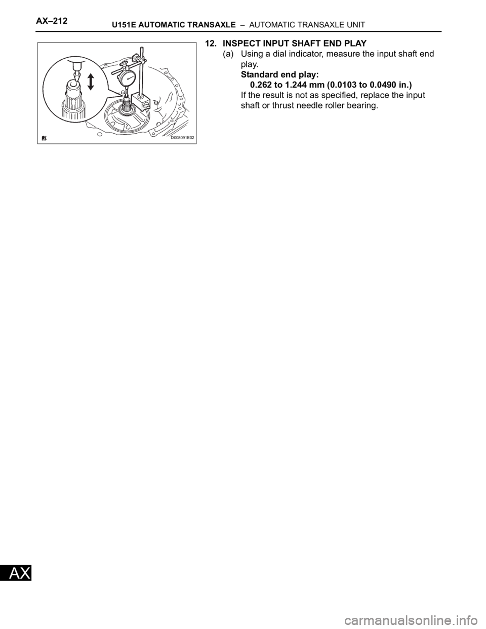
12. INSPECT INPUT SHAFT END PLAY
(a) Using a dial indicator, measure the input shaft end
play.
Standard end play:
0.262 to 1.244 mm (0.0103 to 0.0490 in.)
If the result is not as specified, replace the input
shaft or thrust needle roller bearing.
D008091E02
Page 1087 of 2000
U151E AUTOMATIC TRANSAXLE – AUTOMATIC TRANSAXLE UNITAX–213
AX
REASSEMBLY
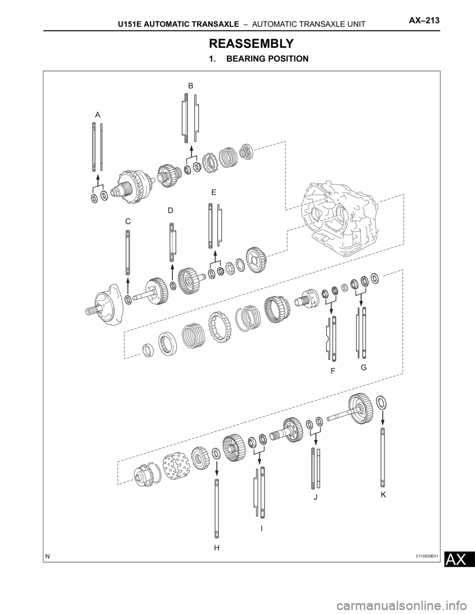
1. BEARING POSITION
C110530E01
Page 1088 of 2000
AX–214U151E AUTOMATIC TRANSAXLE – AUTOMATIC TRANSAXLE UNIT
AX
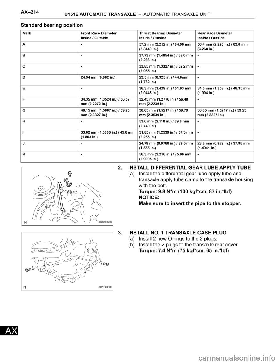
Standard bearing position
2. INSTALL DIFFERENTIAL GEAR LUBE APPLY TUBE
(a) Install the differential gear lube apply tube and
transaxle apply tube clamp to the transaxle housing
with the bolt.
Torque: 9.8 N*m (100 kgf*cm, 87 in.*lbf)
NOTICE:
Make sure to insert the pipe to the stopper.
3. INSTALL NO. 1 TRANSAXLE CASE PLUG
(a) Install 2 new O-rings to the 2 plugs.
(b) Install the 2 plugs to the transaxle rear cover.
Torque: 7.4 N*m (75 kgf*cm, 65 in.*lbf)
Mark Front Race Diameter
Inside / OutsideThrust Bearing Diameter
Inside / OutsideRear Race Diameter
Inside / Outside
A - 57.2 mm (2.252 in.) / 84.96 mm
(3.3449 in.)56.4 mm (2.220 in.) / 83.0 mm
(3.268 in.)
B - 37.73 mm (1.4854 in.) / 58.0 mm
(2.283 in.)-
C - 33.85 mm (1.3327 in.) / 52.2 mm
(2.055 in.)-
D 24.94 mm (0.982 in.) 23.5 mm (0.925 in.) / 44.0mm
(1.732 in.)-
E - 36.3 mm (1.429 in.) / 51.93 mm
(2.0445 in.)34.5 mm (1.358 in.) / 48.35 mm
(1.904 in.)
F 34.35 mm (1.3524 in.) / 56.57
mm (2.2272 in.)32.45 mm (1.2776 in.) / 56.48
mm (2.2236 in.)-
G 40.15 mm (1.5807 in.) / 59.25
mm (2.3327 in.)38.65 mm (1.5217 in.) / 59.79
mm (2.3539 in.)38.65 mm (1.5217 in.) / 59.25
mm (2.3327 in.)
H - 53.6 mm (2.110 in.) / 69.6 mm
(2.740 in.)-
I 33.02 mm (1.3000 in.) / 45.8 mm
(1.803 in.)31.85 mm (1.2539 in.) / 57.3 mm
(2.256 in.)-
J - 24.79 mm (0.9760 in.) / 39.5 mm
(1.555 in.)23.6 mm (0.929 in.) / 37.95 mm
(1.4941 in.)
K - 56.3 mm (2.216 in.) / 75.96 mm
(2.9905 in.)-
D026400E06
D026383E01
Page 1089 of 2000
U151E AUTOMATIC TRANSAXLE – AUTOMATIC TRANSAXLE UNITAX–215
AX
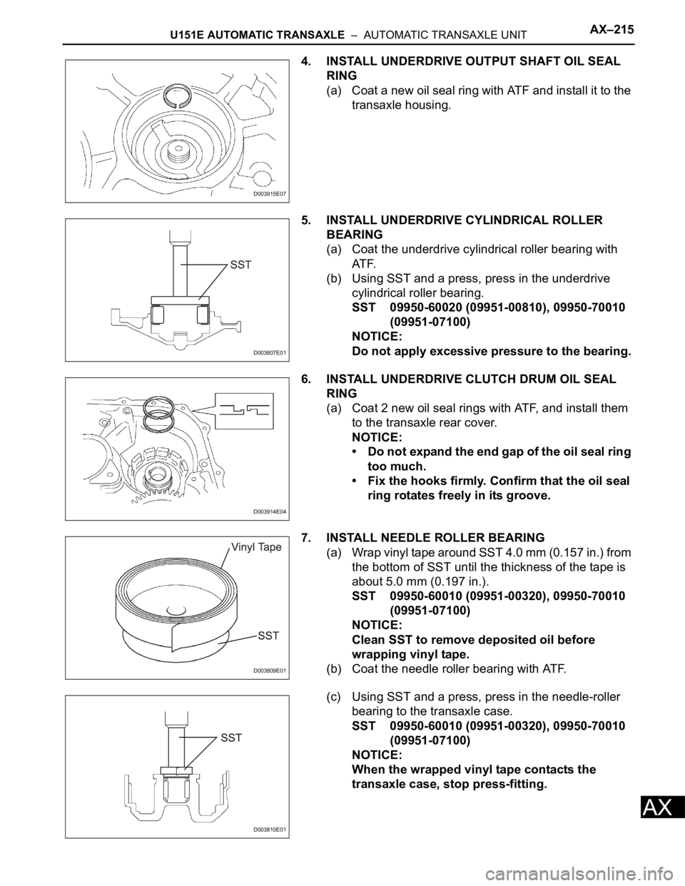
4. INSTALL UNDERDRIVE OUTPUT SHAFT OIL SEAL
RING
(a) Coat a new oil seal ring with ATF and install it to the
transaxle housing.
5. INSTALL UNDERDRIVE CYLINDRICAL ROLLER
BEARING
(a) Coat the underdrive cylindrical roller bearing with
AT F.
(b) Using SST and a press, press in the underdrive
cylindrical roller bearing.
SST 09950-60020 (09951-00810), 09950-70010
(09951-07100)
NOTICE:
Do not apply excessive pressure to the bearing.
6. INSTALL UNDERDRIVE CLUTCH DRUM OIL SEAL
RING
(a) Coat 2 new oil seal rings with ATF, and install them
to the transaxle rear cover.
NOTICE:
• Do not expand the end gap of the oil seal ring
too much.
• Fix the hooks firmly. Confirm that the oil seal
ring rotates freely in its groove.
7. INSTALL NEEDLE ROLLER BEARING
(a) Wrap vinyl tape around SST 4.0 mm (0.157 in.) from
the bottom of SST until the thickness of the tape is
about 5.0 mm (0.197 in.).
SST 09950-60010 (09951-00320), 09950-70010
(09951-07100)
NOTICE:
Clean SST to remove deposited oil before
wrapping vinyl tape.
(b) Coat the needle roller bearing with ATF.
(c) Using SST and a press, press in the needle-roller
bearing to the transaxle case.
SST 09950-60010 (09951-00320), 09950-70010
(09951-07100)
NOTICE:
When the wrapped vinyl tape contacts the
transaxle case, stop press-fitting.
D003915E07
D003807E01
D003914E04
D003809E01
D003810E01
Page 1090 of 2000
AX–216U151E AUTOMATIC TRANSAXLE – AUTOMATIC TRANSAXLE UNIT
AX
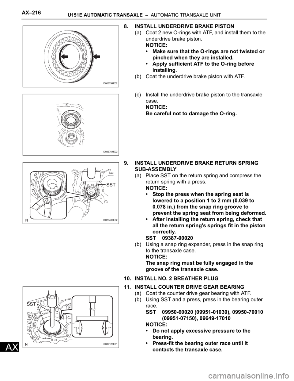
8. INSTALL UNDERDRIVE BRAKE PISTON
(a) Coat 2 new O-rings with ATF, and install them to the
underdrive brake piston.
NOTICE:
• Make sure that the O-rings are not twisted or
pinched when they are installed.
• Apply sufficient ATF to the O-ring before
installing.
(b) Coat the underdrive brake piston with ATF.
(c) Install the underdrive brake piston to the transaxle
case.
NOTICE:
Be careful not to damage the O-ring.
9. INSTALL UNDERDRIVE BRAKE RETURN SPRING
SUB-ASSEMBLY
(a) Place SST on the return spring and compress the
return spring with a press.
NOTICE:
• Stop the press when the spring seat is
lowered to a position 1 to 2 mm (0.039 to
0.078 in.) from the snap ring groove to
prevent the spring seat from being deformed.
• After installing the return spring, check that
all the return spring's springs fit in the piston
correctly.
SST 09387-00020
(b) Using a snap ring expander, press in the snap ring
to the transaxle case.
NOTICE:
The snap ring must be fully engaged in the
groove of the transaxle case.
10. INSTALL NO. 2 BREATHER PLUG
11. INSTALL COUNTER DRIVE GEAR BEARING
(a) Coat the counter drive gear bearing with ATF.
(b) Using SST and a press, press in the bearing outer
race.
SST 09950-60020 (09951-01030), 09950-70010
(09951-07150), 09649-17010
NOTICE:
• Do not apply excessive pressure to the
bearing.
• Press-fit the bearing outer race until it
contacts the transaxle case.
D003794E02
D026764E02
D026407E02
C089126E01