TOYOTA RAV4 2006 Service Repair Manual
Manufacturer: TOYOTA, Model Year: 2006, Model line: RAV4, Model: TOYOTA RAV4 2006Pages: 2000, PDF Size: 45.84 MB
Page 1041 of 2000

U151E AUTOMATIC TRANSAXLE – AUTOMATIC TRANSAXLE SYSTEMAX–25
AX
MONITOR DRIVE PATTERN
1. TEST MONITOR DRIVE PATTERN FOR ECT
CAUTION:
Perform this drive pattern on a level surface and
strictly observe the posted speed limits and traffic
laws while driving.
HINT:
Performing this drive pattern is one method to simulate
the ECT's malfunction detection conditions.
The DTCs may not be detected through ordinary,
everyday driving. Also, DTCs may not be detected
through this drive pattern.
(a) Preparation for driving
(1) Warm up the engine sufficiently (engine coolant
temperature is 60
C (140F) or higher).
(2) Drive the vehicle when the atmospheric
temperature is -10
C (14F) or higher.
Malfunction is not detected when the
atmospheric temperature is less than -10
C
(14
F).
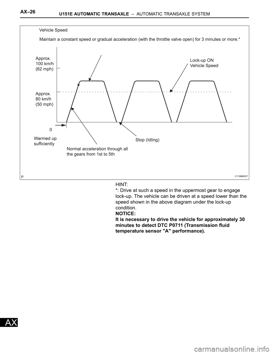
(b) Drive pattern
(1) Drive the vehicle through all the gears.
St o p
1st 2nd 3rd 4th 5th 5th
(lock-up ON).
(2) Repeat the above drive pattern 3 times or more.
NOTICE:
• When using the intelligent tester, the
monitor status can be found in
"ENHANCED OBD II / DATA LIST" or under
"CARB OBD II".
• In the event that the drive pattern must be
interrupted (due to traffic conditions or
other factors), the drive pattern can be
resumed and, in most cases, the monitor
can be completed.
CAUTION:
Perform this drive pattern on a level road as
much as possible and strictly observe the
posted speed limits and traffic laws while
driving.
Page 1042 of 2000
AX–26U151E AUTOMATIC TRANSAXLE – AUTOMATIC TRANSAXLE SYSTEM
AX
HINT:
*: Drive at such a speed in the uppermost gear to engage
lock-up. The vehicle can be driven at a speed lower than the
speed shown in the above diagram under the lock-up
condition.
NOTICE:
It is necessary to drive the vehicle for approximately 30
minutes to detect DTC P0711 (Transmission fluid
temperature sensor "A" performance).
C115866E07
Page 1043 of 2000

U151E AUTOMATIC TRANSAXLE – AUTOMATIC TRANSAXLE SYSTEMAX–27
AX
PROBLEM SYMPTOMS TABLE
HINT:
• Use the table below to help determine the cause of the
problem symptom. The potential causes of the symptoms
are listed in order of probability in the "Suspected area"
column of the table. Check each symptom by checking the
suspected areas in the order they are listed. Replace parts
as necessary.
• The Matrix Chart is divided into 2 chapters. When
troubleshooting, check Chapter 1 first. If instructions are
given in Chapter 1 to proceed to 2, proceed as instructed.
• If the instruction "Proceed to next circuit inspection shown
in problem symptoms table" is given in the flowchart for
each circuit, proceed to the next suspected area in the
table.
• If the problem still occurs even though there are no
malfunctions in any of the circuits, check the ECM and
replace it if necessary.
1. Chapter 1: Electronic Circuit Matrix Chart
Symptom Suspected area See page
No down-shift (a particular gear, from 1st to 4th gear, is
not down-shifted)ECMIN-37
No down-shift (5th -> 4th)1. Transmission control switch (4 <--> D position) circuitAX-44
2. Shift solenoid valve S4 circuit*AX-106
3. ECMIN-37
No up-shift (a particular gear, from 1st to 4th gear, is
not up-shifted)ECMIN-37
No up-shift (4th -> 5th)1. Transmission control switch (4 <--> D position) circuitAX-44
2. Shift solenoid valve S4 circuit*AX-106
3. ECMIN-37
No lock-up1. Stop light switch circuit*AX-62
2. Engine coolant temperature sensor circuit*ES-56
3. ECMIN-37
No lock-up off ECMIN-37
Shift point too high or too low1. Throttle position sensor circuit*ES-56
2. ECMIN-37
Up-shift to 5th from 4th while shift lever on 41. Transmission control switch (4 <--> D position) circuitAX-44
2. ECMIN-37
Up-shift to 5th from 4th while engine is cold1. Engine coolant temperature sensor circuit*ES-56
2. ECMIN-37
Up-shift to 2nd from 1st while shift lever is on L1. Transmission control switch (2 <--> L position) circuit*AX-44
2. ECMIN-37
Harsh engagement (N -> D)1. Shift solenoid valve SL1 circuit*AX-76
2. ECMIN-37
Harsh engagement (lock-up) ECMIN-37
Harsh engagement (any driving position) ECMIN-37
Poor acceleration ECMIN-37
No kick-down ECMIN-37
Engine stalls when starting off or stopping ECMIN-37
Malfunction in shifting1. Park/Neutral position switch circuit*AX-44
2. Transmission control switch (4 <--> D position) circuitAX-44
3. ECMIN-37
Page 1044 of 2000
AX–28U151E AUTOMATIC TRANSAXLE – AUTOMATIC TRANSAXLE SYSTEM
AX
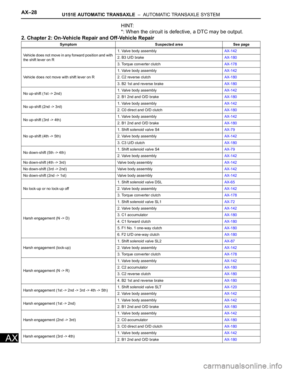
HINT:
*: When the circuit is defective, a DTC may be output.
2. Chapter 2: On-Vehicle Repair and Off-Vehicle Repair
Symptom Suspected area See page
Vehicle does not move in any forward position and with
the shift lever on R1. Valve body assemblyAX-142
2. B3 U/D brakeAX-180
3. Torque converter clutchAX-178
Vehicle does not move with shift lever on R1. Valve body assemblyAX-142
2. C2 reverse clutchAX-180
3. B2 1st and reverse brakeAX-180
No up-shift (1st -> 2nd)1. Valve body assemblyAX-142
2. B1 2nd and O/D brakeAX-180
No up-shift (2nd -> 3rd)1. Valve body assemblyAX-142
2. C0 direct and O/D clutchAX-180
No up-shift (3rd -> 4th)1. Valve body assemblyAX-142
2. B1 2nd and O/D brakeAX-180
No up-shift (4th -> 5th)1. Shift solenoid valve S4AX-79
2. Valve body assemblyAX-142
3. C3 U/D clutchAX-180
No down-shift (5th -> 4th)1. Shift solenoid valve S4AX-79
2. Valve body assemblyAX-142
No down-shift (4th -> 3rd) Valve body assemblyAX-142
No down-shift (3rd -> 2nd) Valve body assemblyAX-142
No down-shift (2nd -> 1st) Valve body assemblyAX-142
No lock-up or no lock-up off1. Shift solenoid valve DSLAX-65
2. Valve body assemblyAX-142
3. Torque converter clutchAX-178
Harsh engagement (N -> D)1. Shift solenoid valve SL1AX-72
2. Valve body assemblyAX-142
3. C1 accumulatorAX-180
4. C1 forward clutchAX-180
5. F1 No. 1 one-way clutchAX-180
6. F2 U/D one-way clutchAX-180
Harsh engagement (lock-up)1. Shift solenoid valve SL2AX-87
2. Valve body assemblyAX-142
3. Torque converter clutchAX-178
Harsh engagement (N -> R)1. Valve body assemblyAX-142
2. C2 accumulatorAX-180
3. C2 reverse clutchAX-180
4. B2 1st and reverse brakeAX-180
Harsh engagement (1st -> 2nd -> 3rd -> 4th -> 5th)1. Shift solenoid valve SLTAX-120
2. Valve body assemblyAX-142
Harsh engagement (1st -> 2nd)1. Valve body assemblyAX-142
2. B1 2nd and O/D brakeAX-180
Harsh engagement (2nd -> 3rd)1. Valve body assemblyAX-142
2. C0 accumulatorAX-180
3. C0 direct and O/D clutchAX-180
Harsh engagement (3rd -> 4th)1. Valve body assemblyAX-142
2. B1 2nd and O/D brakeAX-180
Page 1045 of 2000

U151E AUTOMATIC TRANSAXLE – AUTOMATIC TRANSAXLE SYSTEMAX–29
AX
Harsh engagement (4th -> 5th)1. Valve body assemblyAX-142
2. C3 accumulatorAX-180
3. B3 U/D clutchAX-180
Harsh engagement (5th -> 4th)1. Valve body assemblyAX-142
2. B3 accumulatorAX-180
Slip or shudder (forward and reverse: after warm-up)1. Valve body assemblyAX-142
2. Oil strainerAX-142
3. C0 direct and O/D clutchAX-180
4. C1 forward clutchAX-180
5. C3 U/D clutchAX-180
6. B1 2nd and brakeAX-180
7. B3 U/D brakeAX-180
8. F1 No. 1 one-way clutchAX-180
9. F2 U/D one-way clutchAX-180
10. Torque converter clutchAX-178
Slip or shudder (particular position: just after engine
starts)Torque converter clutchAX-178
Slip or shudder (shift lever on R)1. C2 reverse clutchAX-180
2. B2 1st and reverse brakeAX-180
Slip or shudder (1st)1. C1 forward clutchAX-180
2. F1 No. 1 one-way clutchAX-180
3. F2 U/D one-way clutchAX-180
Slip or shudder (2nd) B1 2nd and O/D brakeAX-180
Slip or shudder (3rd) C0 direct and O/D clutchAX-180
Slip or shudder (4th) B1 2nd and O/D brakeAX-180
Slip or shudder (5th) C3 U/D clutchAX-180
Shift position too high or too low Shift solenoid valve SLTAX-120
No engine braking (1st to 4th/shift lever on D) B3 U/D brakeAX-180
No engine braking (1st/shift lever on L)1. Valve body assemblyAX-142
2. B2 1st and reverse brakeAX-180
No engine braking (2nd/shift lever on 2)1. Valve body assemblyAX-142
2. B1 2nd and O/D brakeAX-180
No engine braking (3rd/shift lever on 3) B3 U/D brakeAX-180
No kick-down Valve body assemblyAX-142
Poor acceleration (all positions)1. Shift solenoid valve SLTAX-120
2. Torque converter clutchAX-178
Poor acceleration (5th)1. C3 U/D clutchAX-180
2. U/D planetary gear unitAX-180
Engine stalls when starting off or stopping1. Shift solenoid valve DSLAX-65
2. Torque converter clutchAX-178 Symptom Suspected area See page
Page 1046 of 2000
AX–30U151E AUTOMATIC TRANSAXLE – AUTOMATIC TRANSAXLE SYSTEM
AX
TERMINALS OF ECM
1. CHECK ECM
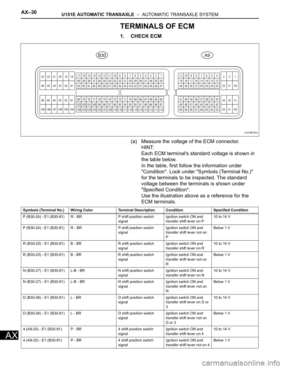
(a) Measure the voltage of the ECM connector.
HINT:
Each ECM terminal's standard voltage is shown in
the table below.
In the table, first follow the information under
"Condition". Look under "Symbols (Terminal No.)"
for the terminals to be inspected. The standard
voltage between the terminals is shown under
"Specified Condition".
Use the illustration above as a reference for the
ECM terminals.
A107881E03
Symbols (Terminal No.) Wiring Color Terminal Description ConditionSpecified Condition
P (B30-24) - E1 (B30-81) R - BR P shift position switch
signalIgnition switch ON and
transfer shift lever on P10 to 14 V
P (B30-24) - E1 (B30-81) R - BR P shift position switch
signalIgnition switch ON and
transfer shift lever not on
PBelow 1 V
R (B30-25) - E1 (B30-81) B - BR R shift position switch
signalIgnition switch ON and
transfer shift lever on R10 to 14 V
R (B30-25) - E1 (B30-81) B - BR R shift position switch
signalIgnition switch ON and
transfer shift lever not on
RBelow 1 V
N (B30-27) - E1 (B30-81) L-B - BR N shift position switch
signalIgnition switch ON and
transfer shift lever on N10 to 14 V
N (B30-27) - E1 (B30-81) L-B - BR N shift position switch
signalIgnition switch ON and
transfer shift lever not on
NBelow 1 V
D (B30-26) - E1 (B30-81) L - BR D shift position switch
signalIgnition switch ON and
transfer shift lever on D or
310 to 14 V
D (B30-26) - E1 (B30-81) L - BR D shift position switch
signalIgnition switch ON and
transfer shift lever not on
D or 3Below 1 V
4 (A9-25) - E1 (B30-81) P - BR 4 shift position switch
signalIgnition switch ON and
transfer shift lever on 410 to 14 V
4 (A9-25) - E1 (B30-81) P - BR 4 shift position switch
signalIgnition switch ON and
transfer shift lever not on 4Below 1 V
Page 1047 of 2000

U151E AUTOMATIC TRANSAXLE – AUTOMATIC TRANSAXLE SYSTEMAX–31
AX
3 (B30-29) - E1 (B30-81) LG - BR 3 shift position switch
signalIgnition switch ON and
transfer shift lever on 310 to 14 V
3 (B30-29) - E1 (B30-81) LG - BR 3 shift position switch
signalIgnition switch ON and
transfer shift lever not on 3Below 1 V
2 (B30-28) - E1 (B30-81) V - BR 2 shift position switch
signalIgnition switch ON and
transfer shift lever on 2
and L10 to 14 V
2 (B30-28) - E1 (B30-81) V - BR 2 shift position switch
signalIgnition switch ON and
transfer shift lever not on 2
and LBelow 1 V
L (A9-26) - E1 (B30-81) V - BR L shift position switch
signalIgnition switch ON and
transfer shift lever on L10 to 14 V
L (A9-26) - E1 (B30-81) V - BR L shift position switch
signalIgnition switch ON and
transfer shift lever not on LBelow 1 V
STP (A9-36) - E1 (B30-81) L - BR Stop light switch signal Brake pedal is depressed Between 10 V and 14 V
STP (A9-36) - E1 (B30-81) L - BR Stop light switch signal Brake pedal is released Below 1 V
SL1+ (B30-16) - SL1-
(B30-17)P - LG SL1 solenoid signal Engine idle speed Pulse generation
(see waveform 1)
SL1+ (B30-16) - SL1-
(B30-17)P - LG SL1 solenoid signal Ignition switch ON Pulse generation
(see waveform 1)
SL1+ (B30-16) - SL1-
(B30-17)P - LG SL1 solenoid signal 1st gear Pulse generation
(see waveform 1)
SL1+ (B30-16) - SL1-
(B30-17)P - LG SL1 solenoid signal Not on 1st gear Below 1 V
SL2+ (B30-12) - SL2-
(B30-13)BR - R SL2 solenoid signal Engine idle speed Pulse generation
(see waveform 2)
SL2+ (B30-12) - SL2-
(B30-13)BR - R SL2 solenoid signal Ignition switch ON Pulse generation
(see waveform 2)
SL2+ (B30-12) - SL2-
(B30-13)BR - R SL2 solenoid signal 1st or 2nd gear Pulse generation
(see waveform 2)
SL2+ (B30-12) - SL2-
(B30-13)BR - R SL2 solenoid signal 3rd, 4th or 5th gear Below 1 V
SL3+ (B30-14) - SL3-
(B30-15)GR - G-R SL3 solenoid signal Engine idle speed Pulse generation
(see waveform 3)
SL3+ (B30-14) - SL3-
(B30-15)GR - G-R SL3 solenoid signal Ignition switch ON Pulse generation
(see waveform 3)
SL3+ (B30-14) - SL3-
(B30-15)GR - G-R SL3 solenoid signal 1st or 2nd gear Pulse generation
(see waveform 3)
SL3+ (B30-14) - SL3-
(B30-15)GR - G-R SL3 solenoid signal 3rd, 4th or 5th gear Below 1 V
DSL (B30-9) - E01 (B30-
22)V - BR DSL solenoid signal Vehicle speed 65 km/h (40
mph), lock-up (ON to OFF)Below 1 V
DSL (B30-9) - E01 (B30-
22)V - BR DSL solenoid signal Vehicle driving under lock-
up positionPulse generation
(see waveform 4)
SLT+ (B30-11) - SLT-
(B30-10)L - W SLT solenoid signal Engine idle speed Pulse generation
(see waveform 5)
SR (B30-8) - E01 (B30-22) G - BR SR solenoid signal Ignition switch ON Below 1 V
SR (B30-8) - E01 (B30-22) G - BR SR solenoid signal 3th, 4th or 5th gear 10 to 14 V
SR (B30-8) - E01 (B30-22) G - BR SR solenoid signal 1st or 2nd gear Below 1 V
S4 (B30-7) - E01 (B30-22) L-B - BR S4 solenoid signal Ignition switch ON Below 1 V
S4 (B30-7) - E01 (B30-22) L-B - BR S4 solenoid signal 5th gear 10 to 14 V
S4 (B30-7) - E01 (B30-22) L-B - BR S4 solenoid signal Not on 5th gear Below 1 V
THO1 (B30-126) - ETHO
(B30-124)Y - B ATF temperature sensor
signalATF temperature 115
C
(239
F) or moreBelow 1.5 V
NT+ (B30-6) - NT- (B30-5) B - G Speed sensor (NT) signal Vehicle speed 20 km/h (12
mph)Pulse generation
(see waveform 6) Symbols (Terminal No.) Wiring Color Terminal Description ConditionSpecified Condition
Page 1048 of 2000
AX–32U151E AUTOMATIC TRANSAXLE – AUTOMATIC TRANSAXLE SYSTEM
AX
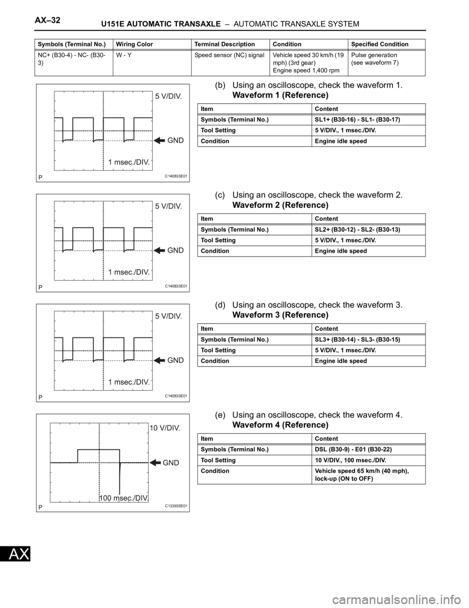
(b) Using an oscilloscope, check the waveform 1.
Waveform 1 (Reference)
(c) Using an oscilloscope, check the waveform 2.
Waveform 2 (Reference)
(d) Using an oscilloscope, check the waveform 3.
Waveform 3 (Reference)
(e) Using an oscilloscope, check the waveform 4.
Waveform 4 (Reference)
NC+ (B30-4) - NC- (B30-
3)W - Y Speed sensor (NC) signal Vehicle speed 30 km/h (19
mph) (3rd gear)
Engine speed 1,400 rpmPulse generation
(see waveform 7) Symbols (Terminal No.) Wiring Color Terminal Description ConditionSpecified Condition
C140833E01
Item Content
Symbols (Terminal No.) SL1+ (B30-16) - SL1- (B30-17)
Tool Setting 5 V/DIV., 1 msec./DIV.
Condition Engine idle speed
C140833E01
Item Content
Symbols (Terminal No.) SL2+ (B30-12) - SL2- (B30-13)
Tool Setting 5 V/DIV., 1 msec./DIV.
Condition Engine idle speed
C140833E01
Item Content
Symbols (Terminal No.) SL3+ (B30-14) - SL3- (B30-15)
Tool Setting 5 V/DIV., 1 msec./DIV.
Condition Engine idle speed
C133935E01
Item Content
Symbols (Terminal No.) DSL (B30-9) - E01 (B30-22)
Tool Setting 10 V/DIV., 100 msec./DIV.
Condition Vehicle speed 65 km/h (40 mph),
lock-up (ON to OFF)
Page 1049 of 2000
U151E AUTOMATIC TRANSAXLE – AUTOMATIC TRANSAXLE SYSTEMAX–33
AX
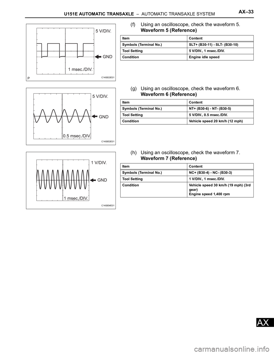
(f) Using an oscilloscope, check the waveform 5.
Waveform 5 (Reference)
(g) Using an oscilloscope, check the waveform 6.
Waveform 6 (Reference)
(h) Using an oscilloscope, check the waveform 7.
Waveform 7 (Reference)
C140833E01
Item Content
Symbols (Terminal No.) SLT+ (B30-11) - SLT- (B30-10)
Tool Setting 5 V/DIV., 1 msec./DIV.
Condition Engine idle speed
C140853E01
Item Content
Symbols (Terminal No.) NT+ (B30-6) - NT- (B30-5)
Tool Setting 5 V/DIV., 0.5 msec./DIV.
Condition Vehicle speed 20 km/h (12 mph)
C140854E01
Item Content
Symbols (Terminal No.) NC+ (B30-4) - NC- (B30-3)
Tool Setting 1 V/DIV., 1 msec./DIV.
Condition Vehicle speed 30 km/h (19 mph) (3rd
gear)
Engine speed 1,400 rpm
Page 1050 of 2000
AX–34U151E AUTOMATIC TRANSAXLE – AUTOMATIC TRANSAXLE SYSTEM
AX
DIAGNOSIS SYSTEM
1. DESCRIPTION
(a) When troubleshooting On-Board Diagnostic (OBD
II) vehicles, the vehicle must be connected to the
OBD II scan tool (complying with SAE J1987).
Various data output from the vehicle's ECM can
then be read.
(b) OBD II regulations require that the vehicle's on-
board computer illuminates the Malfunction
Indicator Lamp (MIL) on the instrument panel when
the computer detects a malfunction in:
(1) The emission control system/components
(2) The powertrain control components (which affect
vehicle emissions)
(3) The computer
In addition, the applicable Diagnostic Trouble
Codes (DTCs) prescribed by SAE J2012 are
recorded in the ECM memory.
When the malfunction does not reoccur, the MIL
stays illuminated until the ignition switch is
turned OFF, and the MIL turns OFF when the
engine is started. However, the DTCs remain
recorded in the ECM memory.
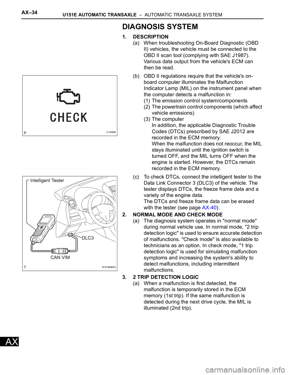
(c) To check DTCs, connect the intelligent tester to the
Data Link Connector 3 (DLC3) of the vehicle. The
tester displays DTCs, the freeze frame data and a
variety of the engine data.
The DTCs and freeze frame data can be erased
with the tester (see page AX-40).
2. NORMAL MODE AND CHECK MODE
(a) The diagnosis system operates in "normal mode"
during normal vehicle use. In normal mode, "2 trip
detection logic" is used to ensure accurate detection
of malfunctions. "Check mode" is also available to
technicians as an option. In check mode, "1 trip
detection logic" is used for simulating malfunction
symptoms and increasing the system's ability to
detect malfunctions, including intermittent
malfunctions.
3. 2 TRIP DETECTION LOGIC
(a) When a malfunction is first detected, the
malfunction is temporarily stored in the ECM
memory (1st trip). If the same malfunction is
detected during the next drive cycle, the MIL is
illuminated (2nd trip).
C140856
B127989E02