TOYOTA RAV4 2006 Service Repair Manual
Manufacturer: TOYOTA, Model Year: 2006,
Model line: RAV4,
Model: TOYOTA RAV4 2006
Pages: 2000, PDF Size: 45.84 MB
TOYOTA RAV4 2006 Service Repair Manual
RAV4 2006
TOYOTA
TOYOTA
https://www.carmanualsonline.info/img/14/57463/w960_57463-0.png
TOYOTA RAV4 2006 Service Repair Manual
Trending: transaxle, Engine cover, fuel cap release, wheel bolt torque, brake fluid, headlight bulb, fuel tank removal
Page 1691 of 2000
RS–42SUPPLEMENTAL RESTRAINT SYSTEM – AIRBAG SYSTEM
RS
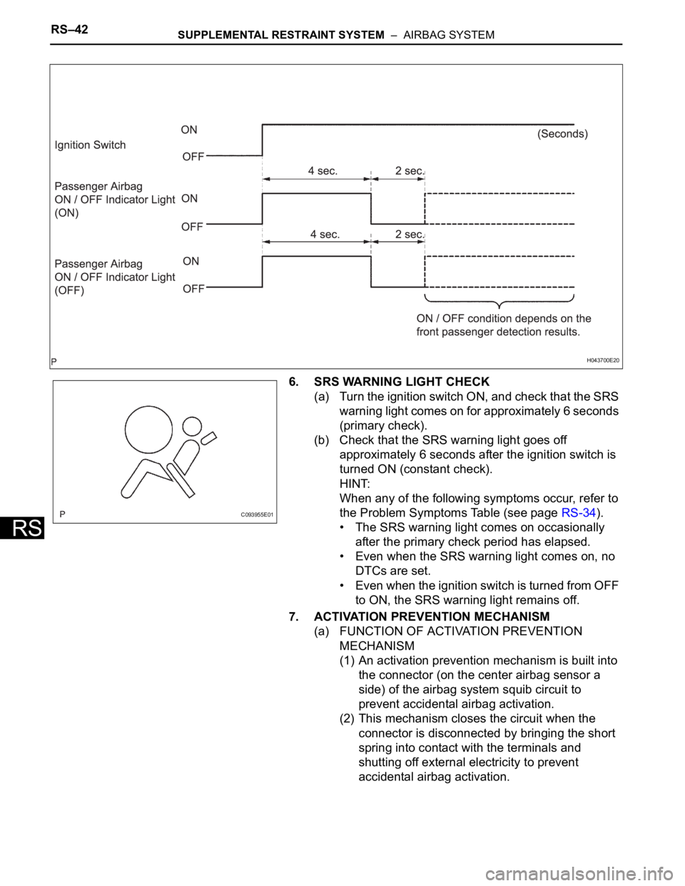
6. SRS WARNING LIGHT CHECK
(a) Turn the ignition switch ON, and check that the SRS
warning light comes on for approximately 6 seconds
(primary check).
(b) Check that the SRS warning light goes off
approximately 6 seconds after the ignition switch is
turned ON (constant check).
HINT:
When any of the following symptoms occur, refer to
the Problem Symptoms Table (see page RS-34).
• The SRS warning light comes on occasionally
after the primary check period has elapsed.
• Even when the SRS warning light comes on, no
DTCs are set.
• Even when the ignition switch is turned from OFF
to ON, the SRS warning light remains off.
7. ACTIVATION PREVENTION MECHANISM
(a) FUNCTION OF ACTIVATION PREVENTION
MECHANISM
(1) An activation prevention mechanism is built into
the connector (on the center airbag sensor a
side) of the airbag system squib circuit to
prevent accidental airbag activation.
(2) This mechanism closes the circuit when the
connector is disconnected by bringing the short
spring into contact with the terminals and
shutting off external electricity to prevent
accidental airbag activation.
H043700E20
C093955E01
Page 1692 of 2000
SUPPLEMENTAL RESTRAINT SYSTEM – AIRBAG SYSTEMRS–43
RS
(b) RELEASE METHOD OF ACTIVATION
PREVENTION MECHANISM
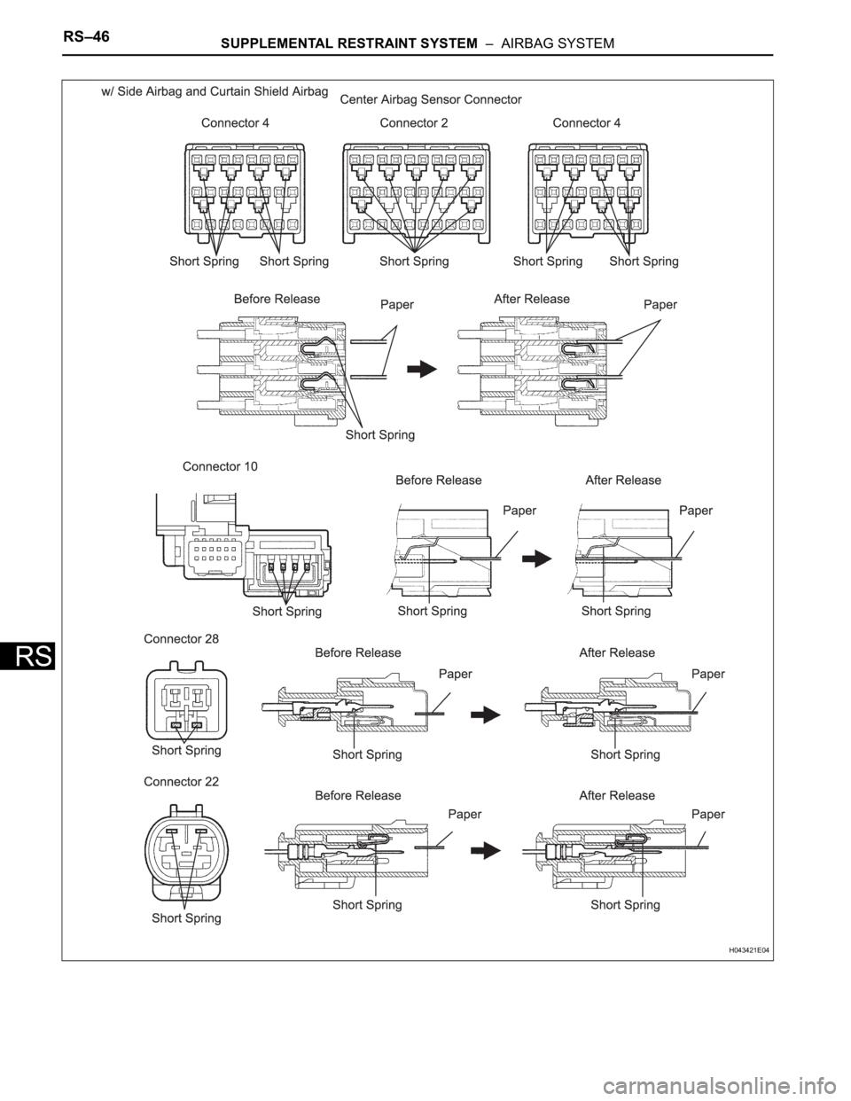
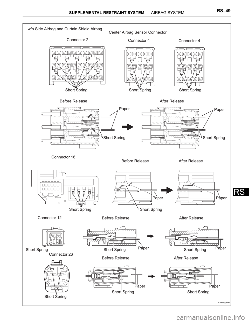
(1) To release the activation prevention mechanism,
insert a piece of paper, with the same thickness
as the male terminal (approximately 0.5 mm
[0.020 in.]), between the terminals and the short
spring to break the connection.
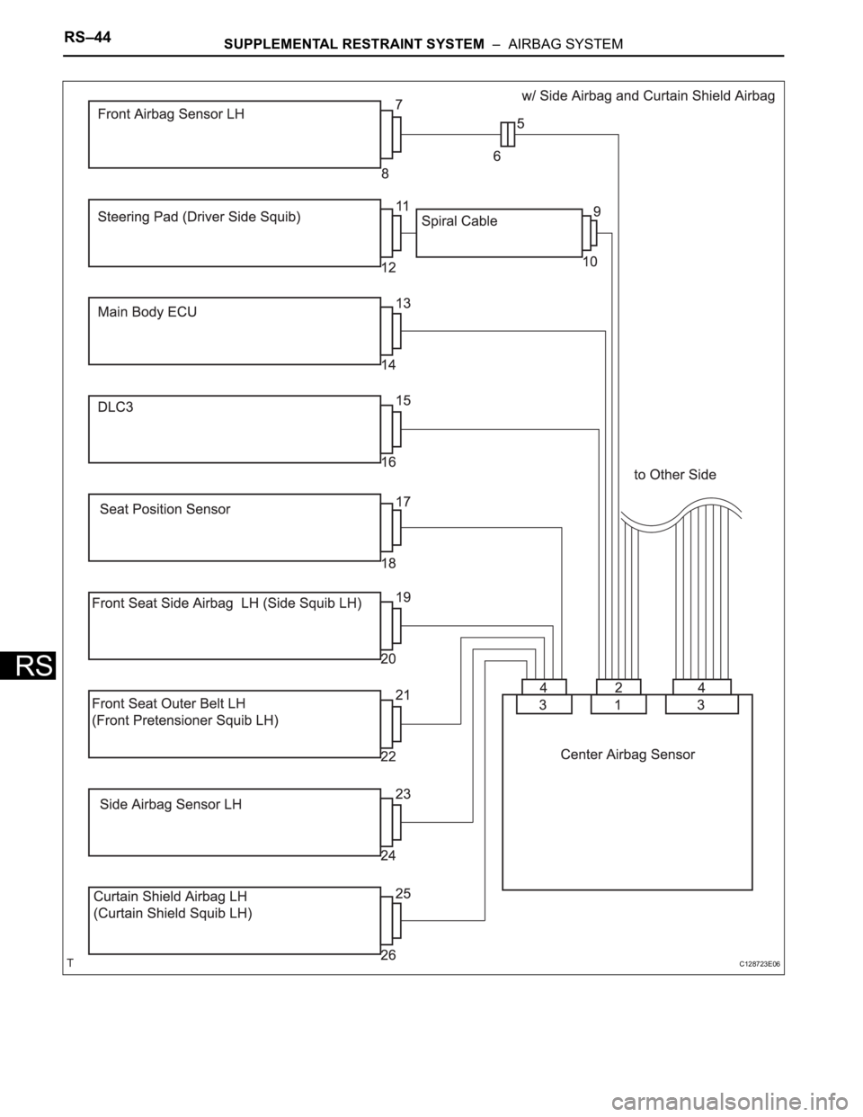
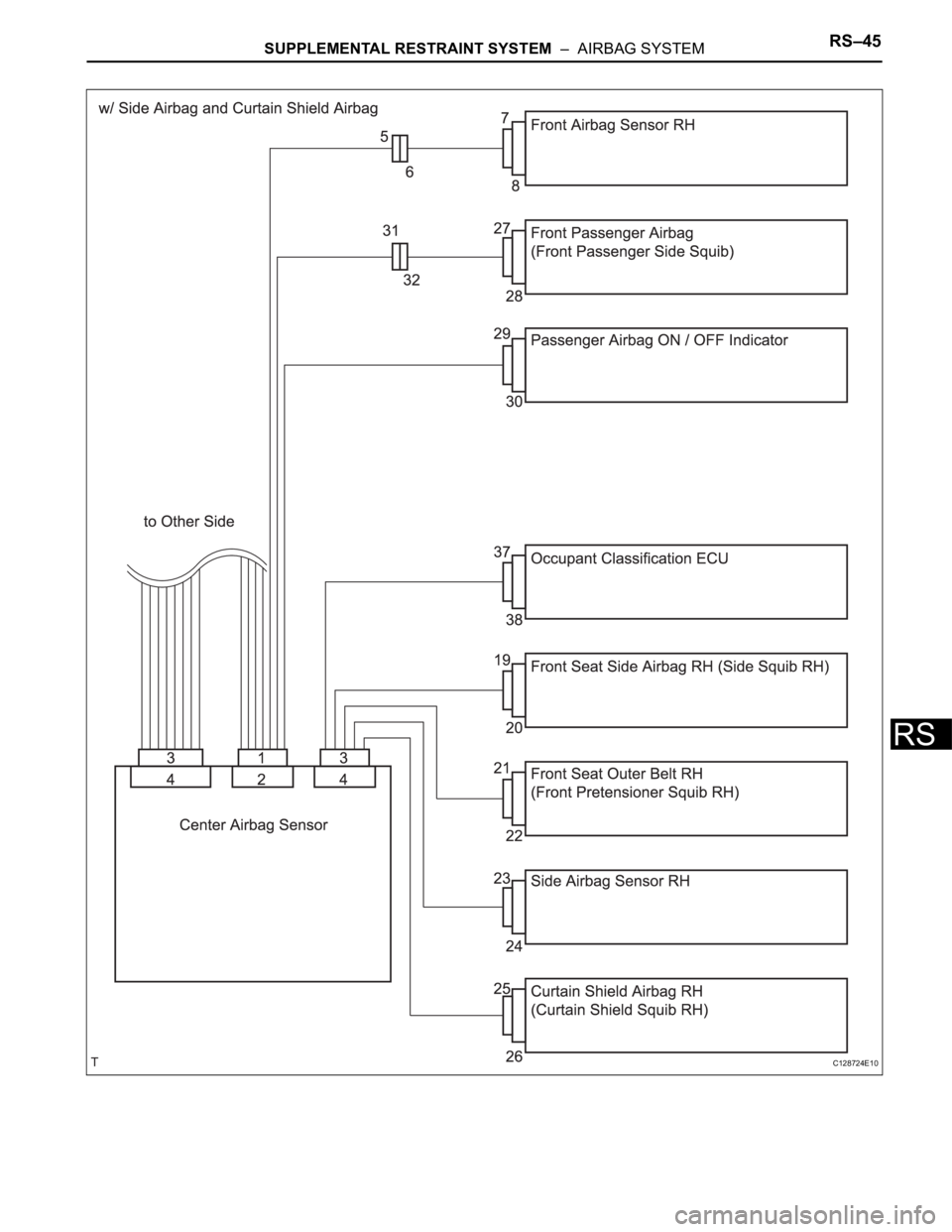
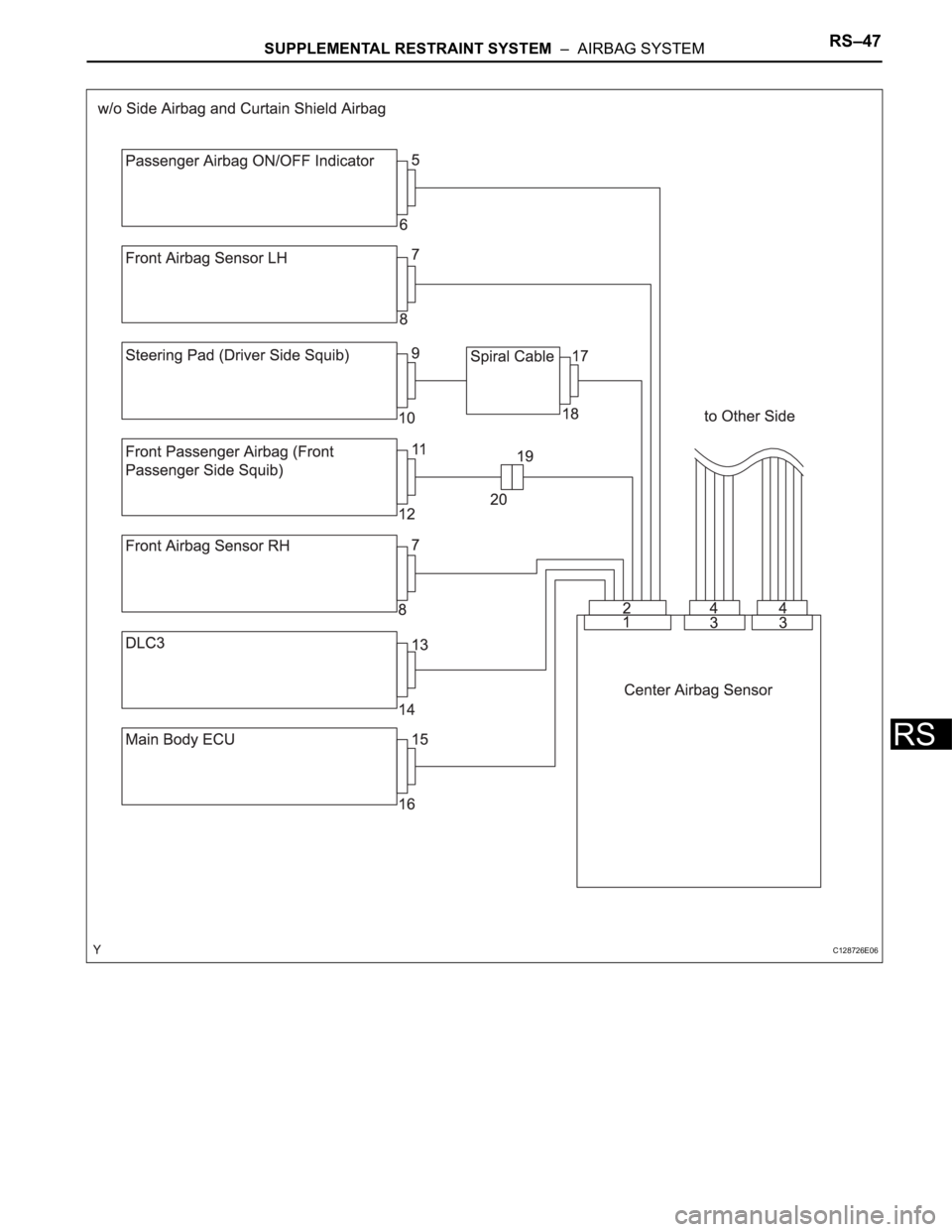
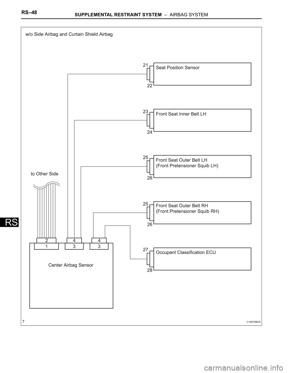
(2) Refer to the illustrations below concerning
connectors to utilize the activation prevention
mechanism and its release method.
CAUTION:
Never release the activation prevention
mechanism on the squib connector even
when inspecting with the squib
disconnected.
NOTICE:
• Do not release the activation prevention
mechanism unless specifically directed to
do so by the troubleshooting procedure.
• To prevent the terminal and the short
spring from being damaged, always use a
piece of paper that is the same thickness
as the male terminal.
Page 1693 of 2000
RS–44SUPPLEMENTAL RESTRAINT SYSTEM – AIRBAG SYSTEM
RS
C128723E06
Page 1694 of 2000
SUPPLEMENTAL RESTRAINT SYSTEM – AIRBAG SYSTEMRS–45
RS
C128724E10
Page 1695 of 2000
RS–46SUPPLEMENTAL RESTRAINT SYSTEM – AIRBAG SYSTEM
RS
H043421E04
Page 1696 of 2000
SUPPLEMENTAL RESTRAINT SYSTEM – AIRBAG SYSTEMRS–47
RS
C128726E06
Page 1697 of 2000
RS–48SUPPLEMENTAL RESTRAINT SYSTEM – AIRBAG SYSTEM
RS
C128725E05
Page 1698 of 2000
SUPPLEMENTAL RESTRAINT SYSTEM – AIRBAG SYSTEMRS–49
RS
H100199E06
Page 1699 of 2000
RS–50SUPPLEMENTAL RESTRAINT SYSTEM – AIRBAG SYSTEM
RS
DTC CHECK / CLEAR
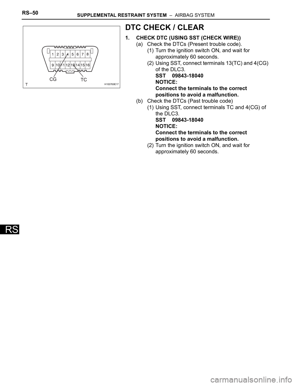
1. CHECK DTC (USING SST (CHECK WIRE))
(a) Check the DTCs (Present trouble code).
(1) Turn the ignition switch ON, and wait for
approximately 60 seconds.
(2) Using SST, connect terminals 13(TC) and 4(CG)
of the DLC3.
SST 09843-18040
NOTICE:
Connect the terminals to the correct
positions to avoid a malfunction.
(b) Check the DTCs (Past trouble code)
(1) Using SST, connect terminals TC and 4(CG) of
the DLC3.
SST 09843-18040
NOTICE:
Connect the terminals to the correct
positions to avoid a malfunction.
(2) Turn the ignition switch ON, and wait for
approximately 60 seconds.
H100769E17
Page 1700 of 2000
SUPPLEMENTAL RESTRAINT SYSTEM – AIRBAG SYSTEMRS–51
RS
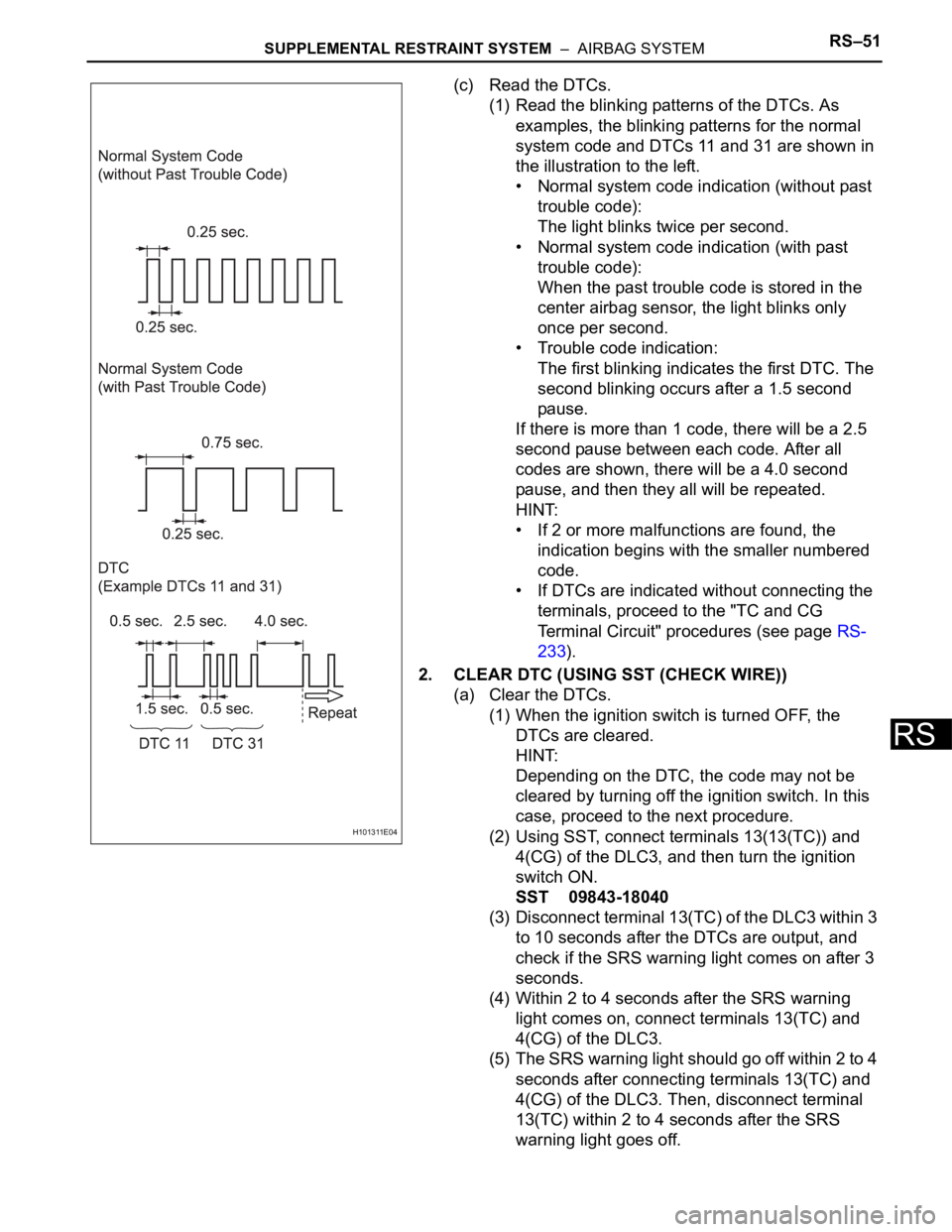
(c) Read the DTCs.
(1) Read the blinking patterns of the DTCs. As
examples, the blinking patterns for the normal
system code and DTCs 11 and 31 are shown in
the illustration to the left.
• Normal system code indication (without past
trouble code):
The light blinks twice per second.
• Normal system code indication (with past
trouble code):
When the past trouble code is stored in the
center airbag sensor, the light blinks only
once per second.
• Trouble code indication:
The first blinking indicates the first DTC. The
second blinking occurs after a 1.5 second
pause.
If there is more than 1 code, there will be a 2.5
second pause between each code. After all
codes are shown, there will be a 4.0 second
pause, and then they all will be repeated.
HINT:
• If 2 or more malfunctions are found, the
indication begins with the smaller numbered
code.
• If DTCs are indicated without connecting the
terminals, proceed to the "TC and CG
Terminal Circuit" procedures (see page RS-
233).
2. CLEAR DTC (USING SST (CHECK WIRE))
(a) Clear the DTCs.
(1) When the ignition switch is turned OFF, the
DTCs are cleared.
HINT:
Depending on the DTC, the code may not be
cleared by turning off the ignition switch. In this
case, proceed to the next procedure.
(2) Using SST, connect terminals 13(13(TC)) and
4(CG) of the DLC3, and then turn the ignition
switch ON.
SST 09843-18040
(3) Disconnect terminal 13(TC) of the DLC3 within 3
to 10 seconds after the DTCs are output, and
check if the SRS warning light comes on after 3
seconds.
(4) Within 2 to 4 seconds after the SRS warning
light comes on, connect terminals 13(TC) and
4(CG) of the DLC3.
(5) The SRS warning light should go off within 2 to 4
seconds after connecting terminals 13(TC) and
4(CG) of the DLC3. Then, disconnect terminal
13(TC) within 2 to 4 seconds after the SRS
warning light goes off.
H101311E04
Trending: Install air manifold, lubric, transaxle, wipers, hood open, pcv valve, timing belt


