TOYOTA RAV4 2006 Service Repair Manual
Manufacturer: TOYOTA, Model Year: 2006, Model line: RAV4, Model: TOYOTA RAV4 2006Pages: 2000, PDF Size: 45.84 MB
Page 821 of 2000
2GR-FE FUEL – FUEL TANKFU–37
FU
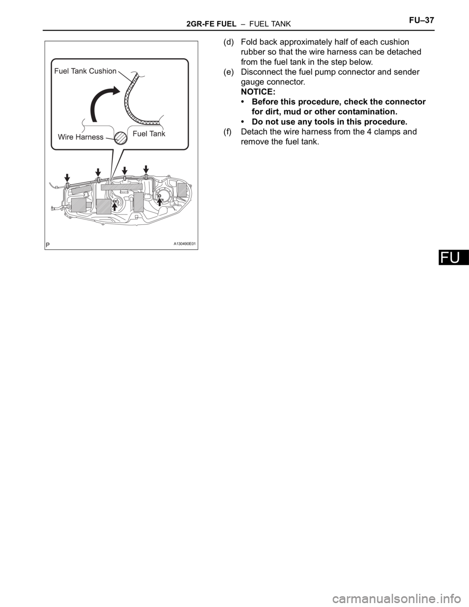
(d) Fold back approximately half of each cushion
rubber so that the wire harness can be detached
from the fuel tank in the step below.
(e) Disconnect the fuel pump connector and sender
gauge connector.
NOTICE:
• Before this procedure, check the connector
for dirt, mud or other contamination.
• Do not use any tools in this procedure.
(f) Detach the wire harness from the 4 clamps and
remove the fuel tank.
A130490E01
Page 822 of 2000
FU–382GR-FE FUEL – FUEL TANK
FU
DISASSEMBLY
1. DISCONNECT FUEL TANK MAIN TUBE SUB-
ASSEMBLY (See page FU-22)
2. REMOVE FUEL TANK VENT TUBE SET PLATE (See
page FU-22)
3. REMOVE FUEL SUCTION WITH PUMP ASSEMBLY
(See page FU-22)
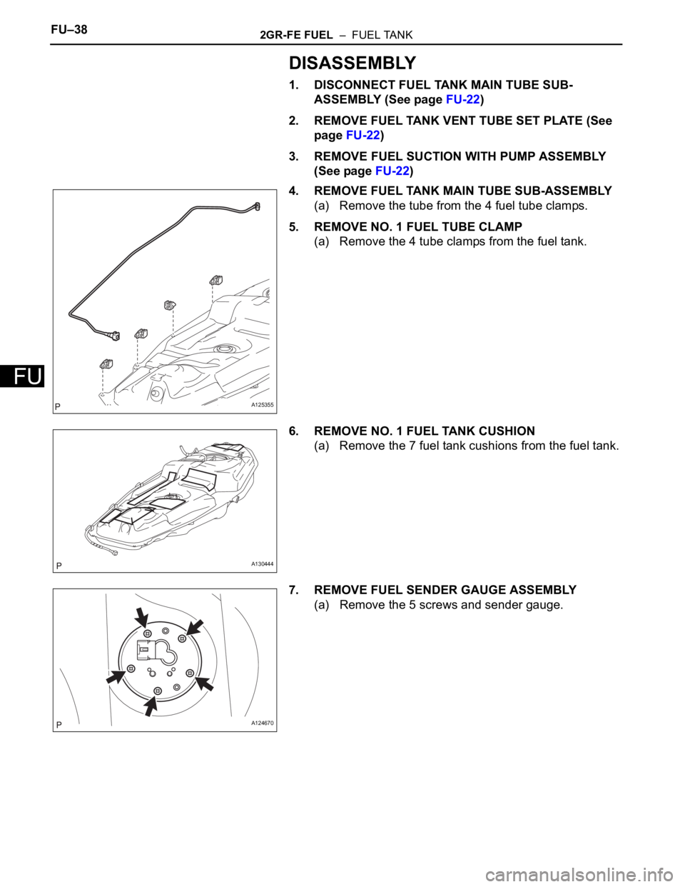
4. REMOVE FUEL TANK MAIN TUBE SUB-ASSEMBLY
(a) Remove the tube from the 4 fuel tube clamps.
5. REMOVE NO. 1 FUEL TUBE CLAMP
(a) Remove the 4 tube clamps from the fuel tank.
6. REMOVE NO. 1 FUEL TANK CUSHION
(a) Remove the 7 fuel tank cushions from the fuel tank.
7. REMOVE FUEL SENDER GAUGE ASSEMBLY
(a) Remove the 5 screws and sender gauge.
A125355
A130444
A124670
Page 823 of 2000
2GR-FE FUEL – FUEL TANKFU–39
FU
REASSEMBLY
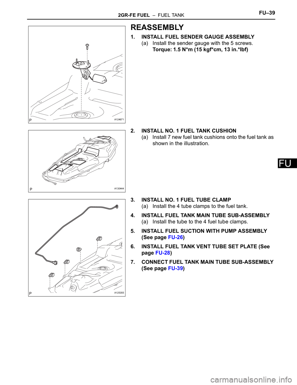
1. INSTALL FUEL SENDER GAUGE ASSEMBLY
(a) Install the sender gauge with the 5 screws.
Torque: 1.5 N*m (15 kgf*cm, 13 in.*lbf)
2. INSTALL NO. 1 FUEL TANK CUSHION
(a) Install 7 new fuel tank cushions onto the fuel tank as
shown in the illustration.
3. INSTALL NO. 1 FUEL TUBE CLAMP
(a) Install the 4 tube clamps to the fuel tank.
4. INSTALL FUEL TANK MAIN TUBE SUB-ASSEMBLY
(a) Install the tube to the 4 fuel tube clamps.
5. INSTALL FUEL SUCTION WITH PUMP ASSEMBLY
(See page FU-26)
6. INSTALL FUEL TANK VENT TUBE SET PLATE (See
page FU-28)
7. CONNECT FUEL TANK MAIN TUBE SUB-ASSEMBLY
(See page FU-39)
A124671
A130444
A125355
Page 824 of 2000
FU–402GR-FE FUEL – FUEL TANK
FU
INSTALLATION
1. INSTALL FUEL TANK ASSEMBLY
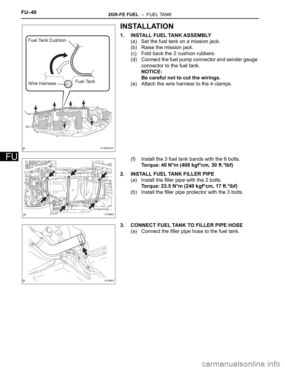
(a) Set the fuel tank on a mission jack.
(b) Raise the mission jack.
(c) Fold back the 2 cushion rubbers.
(d) Connect the fuel pump connector and sender gauge
connector to the fuel tank.
NOTICE:
Be careful not to cut the wirings.
(e) Attach the wire harness to the 4 clamps.
(f) Install the 3 fuel tank bands with the 6 bolts.
Torque: 40 N*m (408 kgf*cm, 30 ft.*lbf)
2. INSTALL FUEL TANK FILLER PIPE
(a) Install the filler pipe with the 2 bolts.
Torque: 23.5 N*m (240 kgf*cm, 17 ft.*lbf)
(b) Install the filler pipe protector with the 3 bolts.
3. CONNECT FUEL TANK TO FILLER PIPE HOSE
(a) Connect the filler pipe hose to the fuel tank.
A130491E01
A124665
A124662
Page 825 of 2000
2GR-FE FUEL – FUEL TANKFU–41
FU
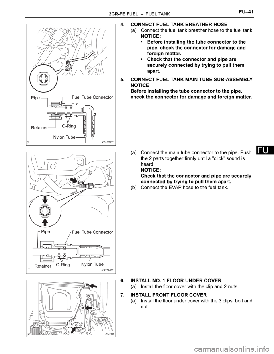
4. CONNECT FUEL TANK BREATHER HOSE
(a) Connect the fuel tank breather hose to the fuel tank.
NOTICE:
• Before installing the tube connector to the
pipe, check the connector for damage and
foreign matter.
• Check that the connector and pipe are
securely connected by trying to pull them
apart.
5. CONNECT FUEL TANK MAIN TUBE SUB-ASSEMBLY
NOTICE:
Before installing the tube connector to the pipe,
check the connector for damage and foreign matter.
(a) Connect the main tube connector to the pipe. Push
the 2 parts together firmly until a "click" sound is
heard.
NOTICE:
Check that the connector and pipe are securely
connected by trying to pull them apart.
(b) Connect the EVAP hose to the fuel tank.
6. INSTALL NO. 1 FLOOR UNDER COVER
(a) Install the floor cover with the clip and 2 nuts.
7. INSTALL FRONT FLOOR COVER
(a) Install the floor under cover with the 3 clips, bolt and
nut.
A131632E01
A127714E01
A124659
Page 826 of 2000
FU–422GR-FE FUEL – FUEL TANK
FU
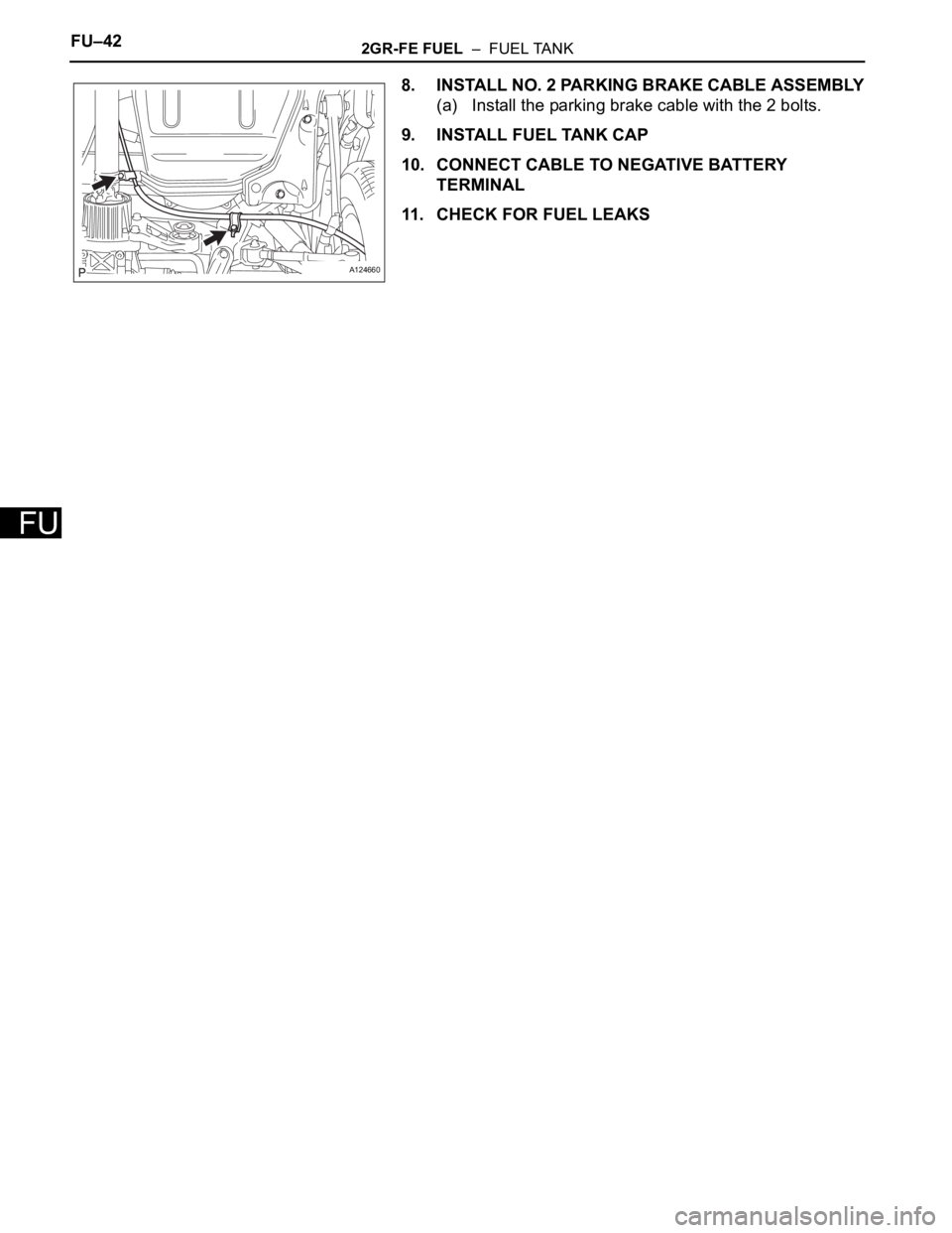
8. INSTALL NO. 2 PARKING BRAKE CABLE ASSEMBLY
(a) Install the parking brake cable with the 2 bolts.
9. INSTALL FUEL TANK CAP
10. CONNECT CABLE TO NEGATIVE BATTERY
TERMINAL
11. CHECK FOR FUEL LEAKS
A124660
Page 827 of 2000
2AZ-FE EMISSION CONTROL – CANISTEREC–11
EC
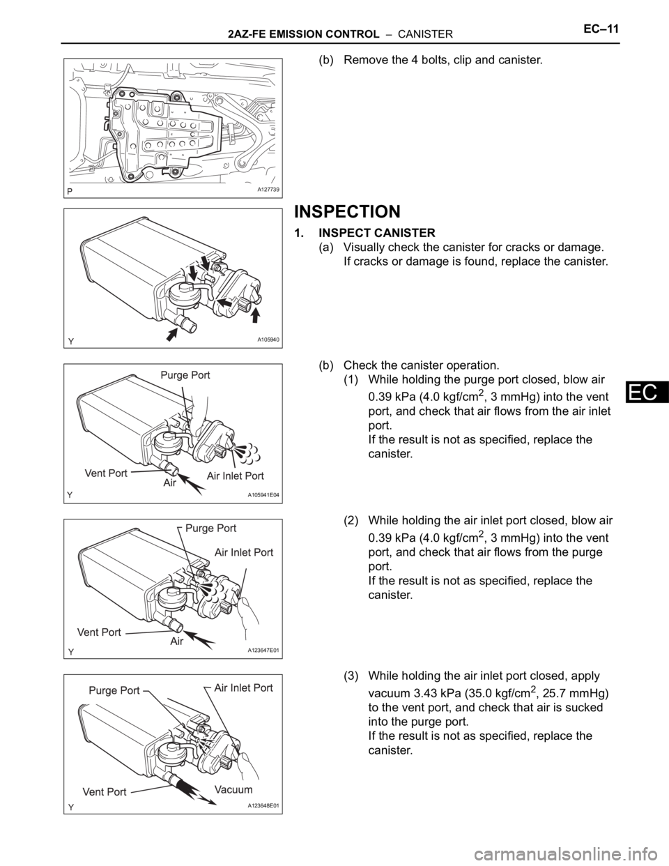
(b) Remove the 4 bolts, clip and canister.
INSPECTION
1. INSPECT CANISTER
(a) Visually check the canister for cracks or damage.
If cracks or damage is found, replace the canister.
(b) Check the canister operation.
(1) While holding the purge port closed, blow air
0.39 kPa (4.0 kgf/cm
2, 3 mmHg) into the vent
port, and check that air flows from the air inlet
port.
If the result is not as specified, replace the
canister.
(2) While holding the air inlet port closed, blow air
0.39 kPa (4.0 kgf/cm
2, 3 mmHg) into the vent
port, and check that air flows from the purge
port.
If the result is not as specified, replace the
canister.
(3) While holding the air inlet port closed, apply
vacuum 3.43 kPa (35.0 kgf/cm
2, 25.7 mmHg)
to the vent port, and check that air is sucked
into the purge port.
If the result is not as specified, replace the
canister.
A127739
A105940
A105941E04
A123647E01
A123648E01
Page 828 of 2000
EC–122AZ-FE EMISSION CONTROL – CANISTER
EC
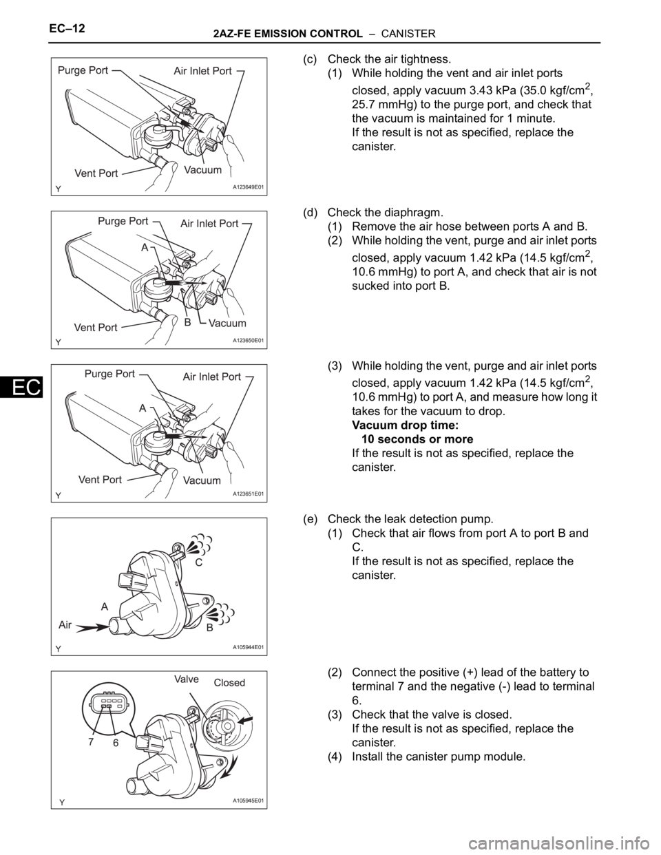
(c) Check the air tightness.
(1) While holding the vent and air inlet ports
closed, apply vacuum 3.43 kPa (35.0 kgf/cm
2,
25.7 mmHg) to the purge port, and check that
the vacuum is maintained for 1 minute.
If the result is not as specified, replace the
canister.
(d) Check the diaphragm.
(1) Remove the air hose between ports A and B.
(2) While holding the vent, purge and air inlet ports
closed, apply vacuum 1.42 kPa (14.5 kgf/cm
2,
10.6 mmHg) to port A, and check that air is not
sucked into port B.
(3) While holding the vent, purge and air inlet ports
closed, apply vacuum 1.42 kPa (14.5 kgf/cm
2,
10.6 mmHg) to port A, and measure how long it
takes for the vacuum to drop.
Vacuum drop time:
10 seconds or more
If the result is not as specified, replace the
canister.
(e) Check the leak detection pump.
(1) Check that air flows from port A to port B and
C.
If the result is not as specified, replace the
canister.
(2) Connect the positive (+) lead of the battery to
terminal 7 and the negative (-) lead to terminal
6.
(3) Check that the valve is closed.
If the result is not as specified, replace the
canister.
(4) Install the canister pump module.
A123649E01
A123650E01
A123651E01
A105944E01
A105945E01
Page 829 of 2000
2AZ-FE EMISSION CONTROL – CANISTEREC–13
EC
INSTALLATION
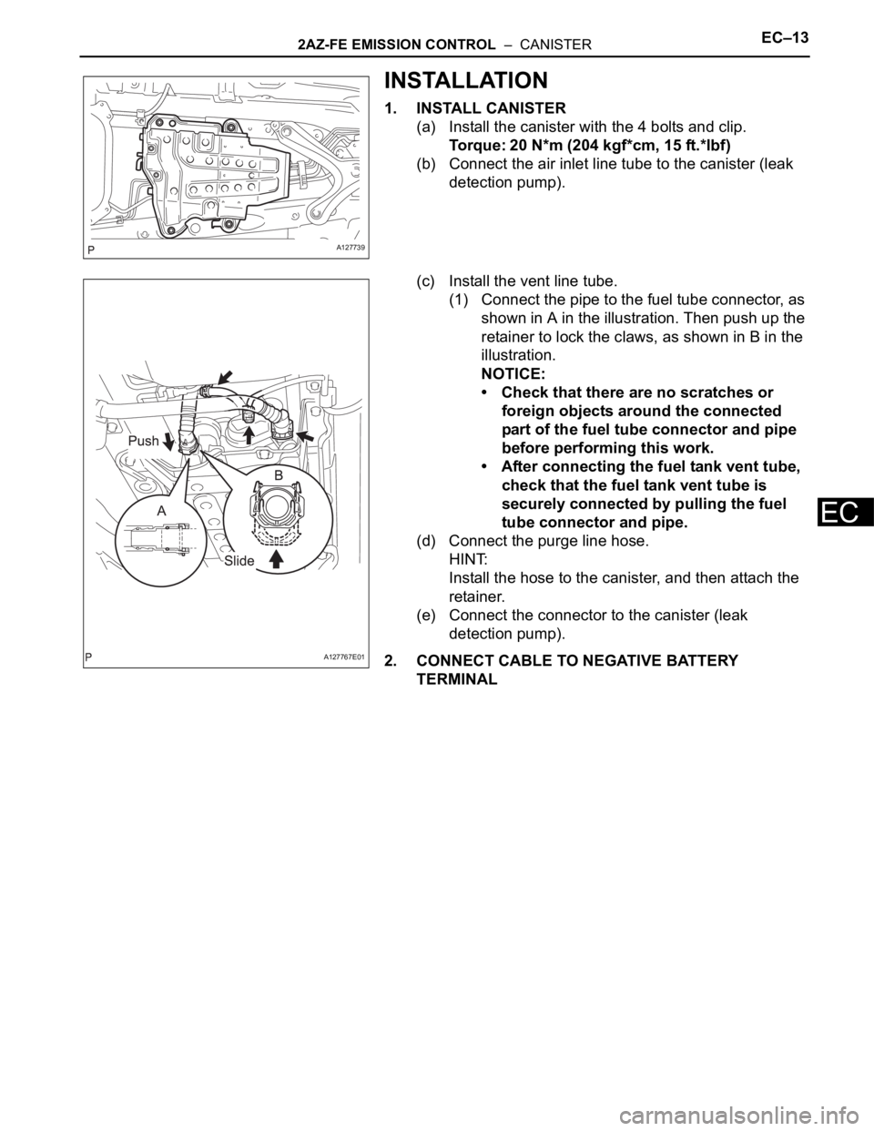
1. INSTALL CANISTER
(a) Install the canister with the 4 bolts and clip.
Torque: 20 N*m (204 kgf*cm, 15 ft.*lbf)
(b) Connect the air inlet line tube to the canister (leak
detection pump).
(c) Install the vent line tube.
(1) Connect the pipe to the fuel tube connector, as
shown in A in the illustration. Then push up the
retainer to lock the claws, as shown in B in the
illustration.
NOTICE:
• Check that there are no scratches or
foreign objects around the connected
part of the fuel tube connector and pipe
before performing this work.
• After connecting the fuel tank vent tube,
check that the fuel tank vent tube is
securely connected by pulling the fuel
tube connector and pipe.
(d) Connect the purge line hose.
HINT:
Install the hose to the canister, and then attach the
retainer.
(e) Connect the connector to the canister (leak
detection pump).
2. CONNECT CABLE TO NEGATIVE BATTERY
TERMINAL
A127739
A127767E01
Page 830 of 2000
2AZ-FE EMISSION CONTROL – VENTILATION VALVEEC–19
EC
INSTALLATION
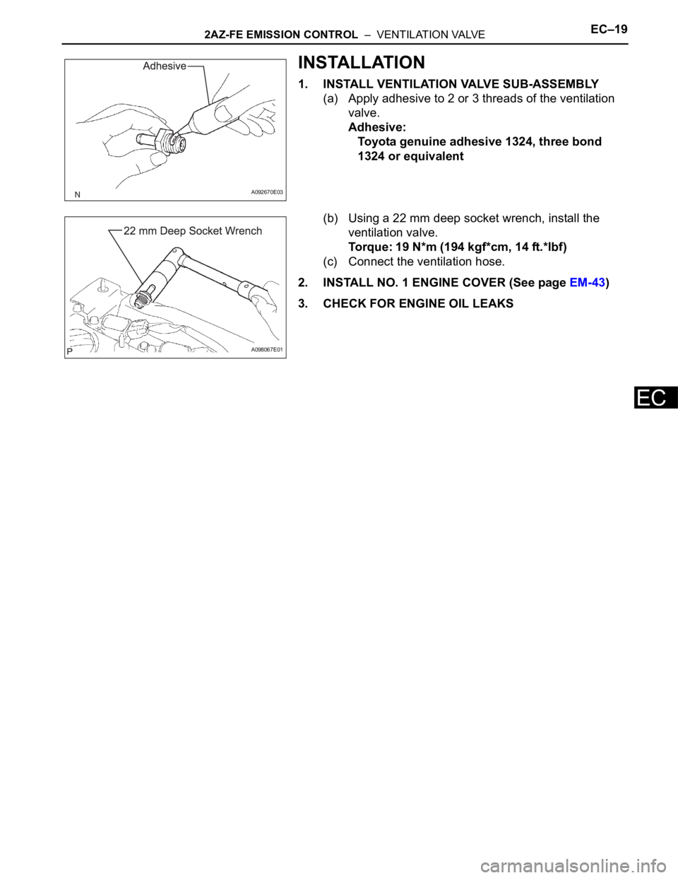
1. INSTALL VENTILATION VALVE SUB-ASSEMBLY
(a) Apply adhesive to 2 or 3 threads of the ventilation
valve.
Adhesive:
Toyota genuine adhesive 1324, three bond
1324 or equivalent
(b) Using a 22 mm deep socket wrench, install the
ventilation valve.
Torque: 19 N*m (194 kgf*cm, 14 ft.*lbf)
(c) Connect the ventilation hose.
2. INSTALL NO. 1 ENGINE COVER (See page EM-43)
3. CHECK FOR ENGINE OIL LEAKS
A092670E03
A098067E01