TOYOTA RAV4 2006 Service Repair Manual
Manufacturer: TOYOTA, Model Year: 2006,
Model line: RAV4,
Model: TOYOTA RAV4 2006
Pages: 2000, PDF Size: 45.84 MB
TOYOTA RAV4 2006 Service Repair Manual
RAV4 2006
TOYOTA
TOYOTA
https://www.carmanualsonline.info/img/14/57463/w960_57463-0.png
TOYOTA RAV4 2006 Service Repair Manual
Trending: coolant capacity, absorber, Sensor O2, c1299, fuel pump circuit, warning light, dimensions
Page 891 of 2000
PP–70PREPARATION – DIFFERENTIAL
PP
RECOMMENDED TOOLS
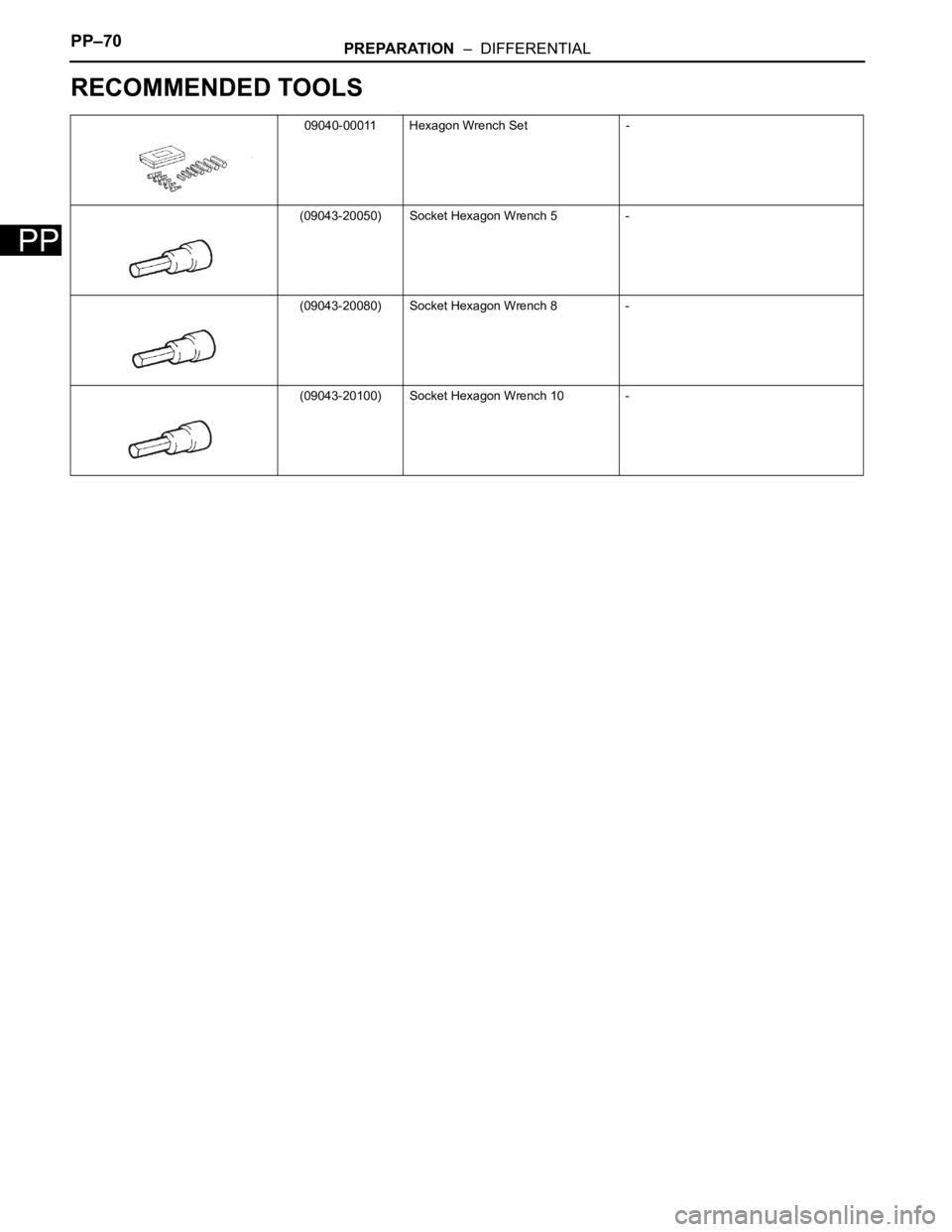
09040-00011 Hexagon Wrench Set -
(09043-20050) Socket Hexagon Wrench 5 -
(09043-20080) Socket Hexagon Wrench 8 -
(09043-20100) Socket Hexagon Wrench 10 -
Page 892 of 2000
PREPARATION – DIFFERENTIALPP–71
PP
EQUIPMENT
Chisel
Dial indicator with magnetic base
Plastic-faced hammer
Torque wrench
Page 893 of 2000
PP–72PREPARATION – DIFFERENTIAL
PP
LUBRICANT
Item Capacity Classification
Rear differential oil 0.45 to 0.55 liters (0.48 to 0.58 US qts., 0.40
to 0.48 Imp. qts.)Hypoid gear oil API GL-5 or equivalent
Page 894 of 2000
PREPARATION – DIFFERENTIALPP–73
PP
SSM
Toyota Genuine Seal Packing 1281
Three Bond 1281 or Equivalent-
Page 895 of 2000
2GR-FE IGNITION – IGNITION SYSTEMIG–5
IG
ON-VEHICLE INSPECTION
1. CHECK IGNITION COIL ASSEMBLY AND PERFORM
SPARK TEST
NOTICE:
In this section, the terms "Cold" and "Hot" refer to
the temperature of the sensor. "Cold" means
approximately -10 to 50
C (14 to 122F). "Hot" means
approximately 50 to 100
C (122 to 212F).
(a) Check the DTCs.
NOTICE:
If a DTC is present, perform troubleshooting in
accordance with the procedure for that DTC.
(b) Check that sparks occur.
(1) Remove the V-bank cover.
(2) Remove the intake air surge tank (see page
EM-27).
(3) Remove the bolt and ignition coil.
(4) Using a 16 mm spark plug wrench, remove the
spark plug.
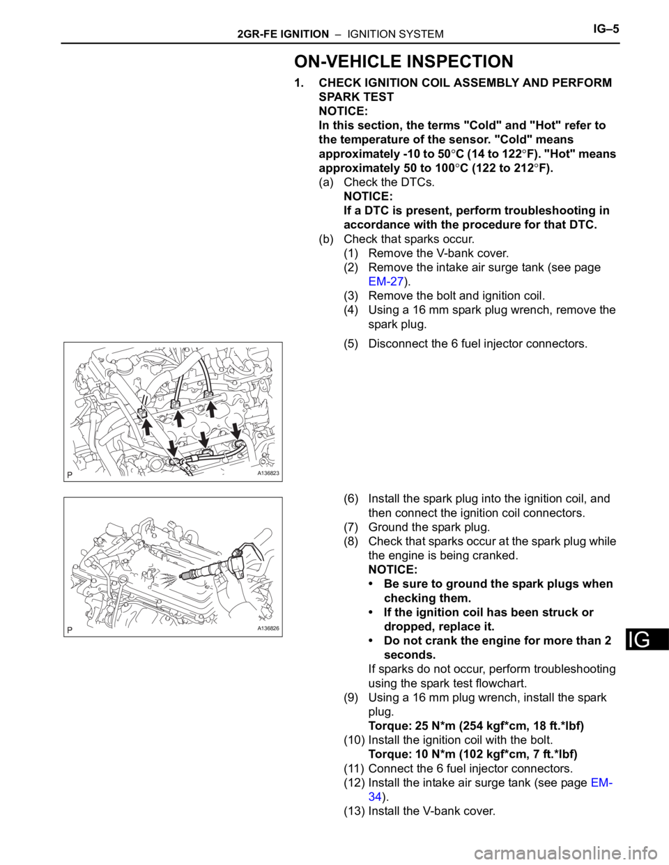
(5) Disconnect the 6 fuel injector connectors.
(6) Install the spark plug into the ignition coil, and
then connect the ignition coil connectors.
(7) Ground the spark plug.
(8) Check that sparks occur at the spark plug while
the engine is being cranked.
NOTICE:
• Be sure to ground the spark plugs when
checking them.
• If the ignition coil has been struck or
dropped, replace it.
• Do not crank the engine for more than 2
seconds.
If sparks do not occur, perform troubleshooting
using the spark test flowchart.
(9) Using a 16 mm plug wrench, install the spark
plug.
Torque: 25 N*m (254 kgf*cm, 18 ft.*lbf)
(10) Install the ignition coil with the bolt.
Torque: 10 N*m (102 kgf*cm, 7 ft.*lbf)
(11) Connect the 6 fuel injector connectors.
(12) Install the intake air surge tank (see page EM-
34).
(13) Install the V-bank cover.
A136823
A136826
Page 896 of 2000
IG–62GR-FE IGNITION – IGNITION SYSTEM
IG
(c) Perform troubleshooting using the spark test
flowchart.
(1) Check that the ignition coil connector is
securely connected.
Result
(2) Perform the spark test on each ignition coil.
1. Replace the ignition coil with a normal one.
2. Perform the spark test again.
Result
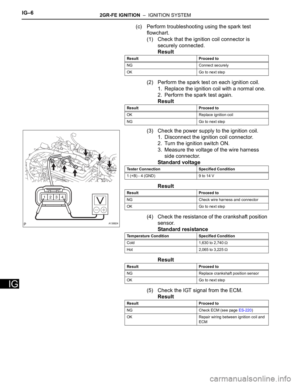
(3) Check the power supply to the ignition coil.
1. Disconnect the ignition coil connector.
2. Turn the ignition switch ON.
3. Measure the voltage of the wire harness
side connector.
Standard voltage
Result
(4) Check the resistance of the crankshaft position
sensor.
Standard resistance
Result
(5) Check the IGT signal from the ECM.
Result
Result Proceed to
NG Connect securely
OK Go to next step
Result Proceed to
OK Replace ignition coil
NG Go to next step
A136824
Tester Connection Specified Condition
1 (+B) - 4 (GND) 9 to 14 V
Result Proceed to
NG Check wire harness and connector
OK Go to next step
Temperature Condition Specified Condition
Cold 1,630 to 2,740
Hot 2,065 to 3,225
Result Proceed to
NG Replace crankshaft position sensor
OK Go to next step
Result Proceed to
NG Check ECM (see page ES-220)
OK Repair wiring between ignition coil and
ECM
Page 897 of 2000
2GR-FE IGNITION – IGNITION SYSTEMIG–7
IG
2. CHECK SPARK PLUG
(a) Check the electrode with megohmmeter:
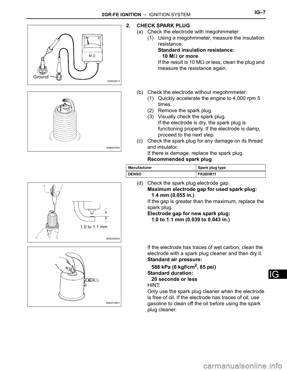
(1) Using a megohmmeter, measure the insulation
resistance.
Standard insulation resistance:
10 M
or more
If the result is 10 M
or less, clean the plug and
measure the resistance again.
(b) Check the electrode without megohmmeter:
(1) Quickly accelerate the engine to 4,000 rpm 5
times.
(2) Remove the spark plug.
(3) Visually check the spark plug.
If the electrode is dry, the spark plug is
functioning properly. If the electrode is damp,
proceed to the next step.
(c) Check the spark plug for any damage on its thread
and insulator.
If there is damage, replace the spark plug.
Recommended spark plug
(d) Check the spark plug electrode gap.
Maximum electrode gap for used spark plug:
1.4 mm (0.055 in.)
If the gap is greater than the maximum, replace the
spark plug.
Electrode gap for new spark plug:
1.0 to 1.1 mm (0.039 to 0.043 in.)
If the electrode has traces of wet carbon, clean the
electrode with a spark plug cleaner and then dry it.
Standard air pressure:
588 kPa (6 kgf/cm
2, 85 psi)
Standard duration:
20 seconds or less
HINT:
Only use the spark plug cleaner when the electrode
is free of oil. If the electrode has traces of oil, use
gasoline to clean off the oil before using the spark
plug cleaner.
I039522E10
A088307E02
Manufacturer Spark plug type
DENSO FK20HR11
B002630E04
B062019E01
Page 898 of 2000
ST–62AZ-FE STARTING – STARTER
ST
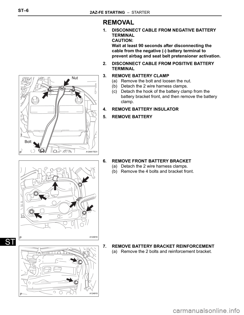
REMOVAL
1. DISCONNECT CABLE FROM NEGATIVE BATTERY
TERMINAL
CAUTION:
Wait at least 90 seconds after disconnecting the
cable from the negative (-) battery terminal to
prevent airbag and seat belt pretensioner activation.
2. DISCONNECT CABLE FROM POSITIVE BATTERY
TERMINAL
3. REMOVE BATTERY CLAMP
(a) Remove the bolt and loosen the nut.
(b) Detach the 2 wire harness clamps.
(c) Detach the hook of the battery clamp from the
battery bracket front, and then remove the battery
clamp.
4. REMOVE BATTERY INSULATOR
5. REMOVE BATTERY
6. REMOVE FRONT BATTERY BRACKET
(a) Detach the 2 wire harness clamps.
(b) Remove the 4 bolts and bracket front.
7. REMOVE BATTERY BRACKET REINFORCEMENT
(a) Remove the 2 bolts and reinforcement bracket.
A124917E01
A124918
A124919
Page 899 of 2000
2AZ-FE STARTING – STARTERST–7
ST
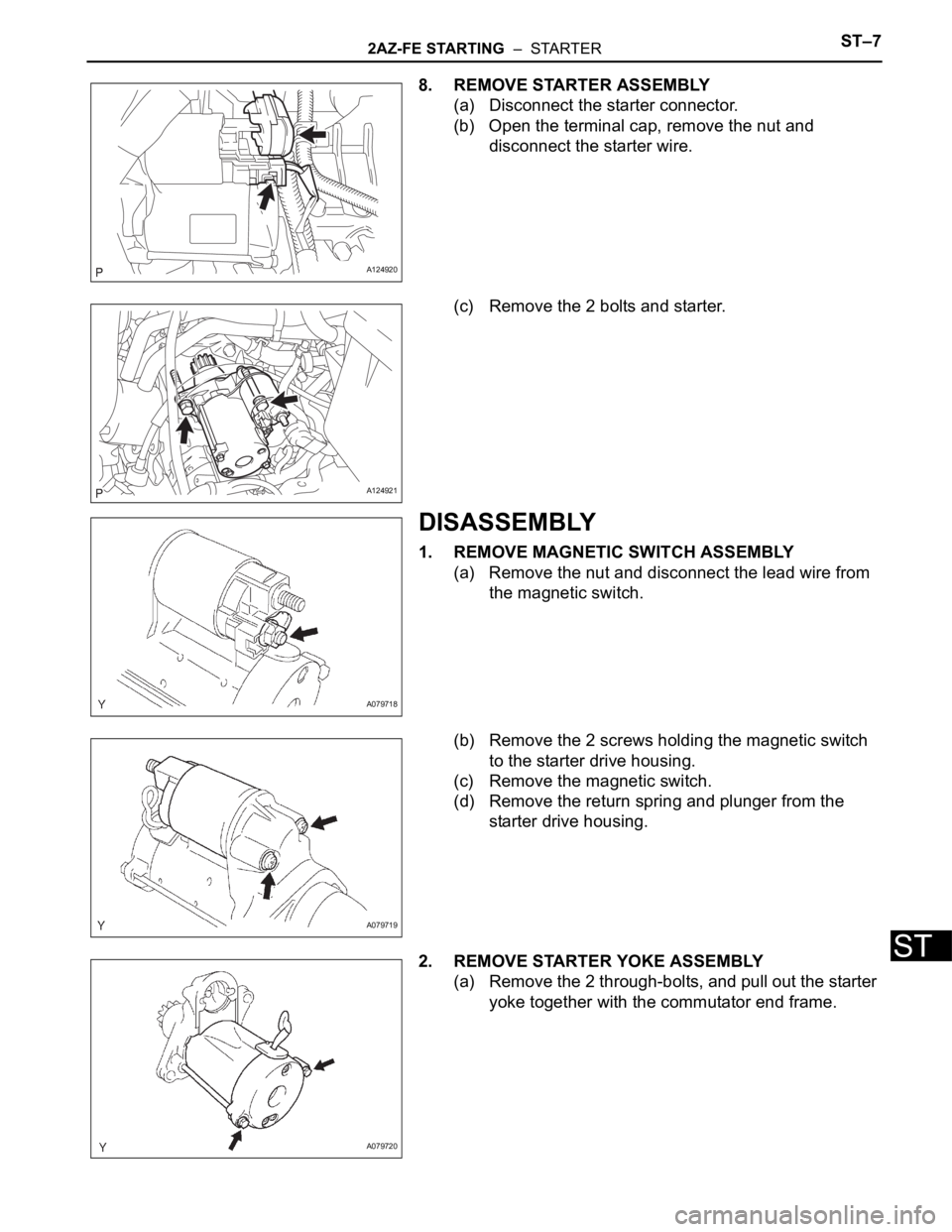
8. REMOVE STARTER ASSEMBLY
(a) Disconnect the starter connector.
(b) Open the terminal cap, remove the nut and
disconnect the starter wire.
(c) Remove the 2 bolts and starter.
DISASSEMBLY
1. REMOVE MAGNETIC SWITCH ASSEMBLY
(a) Remove the nut and disconnect the lead wire from
the magnetic switch.
(b) Remove the 2 screws holding the magnetic switch
to the starter drive housing.
(c) Remove the magnetic switch.
(d) Remove the return spring and plunger from the
starter drive housing.
2. REMOVE STARTER YOKE ASSEMBLY
(a) Remove the 2 through-bolts, and pull out the starter
yoke together with the commutator end frame.
A124920
A124921
A079718
A079719
A079720
Page 900 of 2000
ST–82AZ-FE STARTING – STARTER
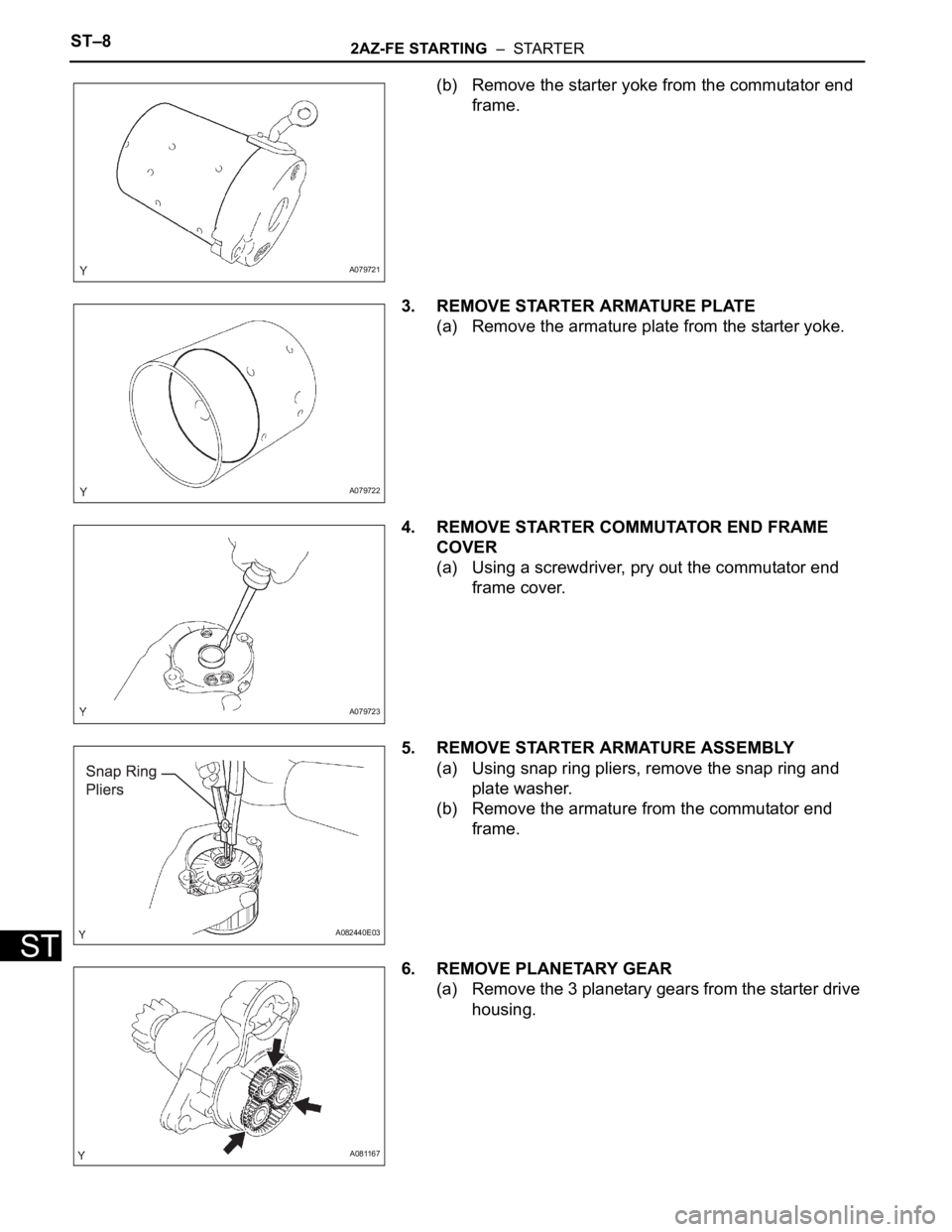
ST
(b) Remove the starter yoke from the commutator end
frame.
3. REMOVE STARTER ARMATURE PLATE
(a) Remove the armature plate from the starter yoke.
4. REMOVE STARTER COMMUTATOR END FRAME
COVER
(a) Using a screwdriver, pry out the commutator end
frame cover.
5. REMOVE STARTER ARMATURE ASSEMBLY
(a) Using snap ring pliers, remove the snap ring and
plate washer.
(b) Remove the armature from the commutator end
frame.
6. REMOVE PLANETARY GEAR
(a) Remove the 3 planetary gears from the starter drive
housing.
A079721
A079722
A079723
A082440E03
A081167
Trending: Brake, key battery, fuses, engine diagram, wheel bolts, Water pump install, high beam
