TOYOTA RAV4 2006 Service Repair Manual
Manufacturer: TOYOTA, Model Year: 2006,
Model line: RAV4,
Model: TOYOTA RAV4 2006
Pages: 2000, PDF Size: 45.84 MB
TOYOTA RAV4 2006 Service Repair Manual
RAV4 2006
TOYOTA
TOYOTA
https://www.carmanualsonline.info/img/14/57463/w960_57463-0.png
TOYOTA RAV4 2006 Service Repair Manual
Trending: jump start, Control arm, change wheel, transmission oil, layout, Oxygen sensor, charging
Page 871 of 2000
CO–422GR-FE COOLING – RADIATOR
CO
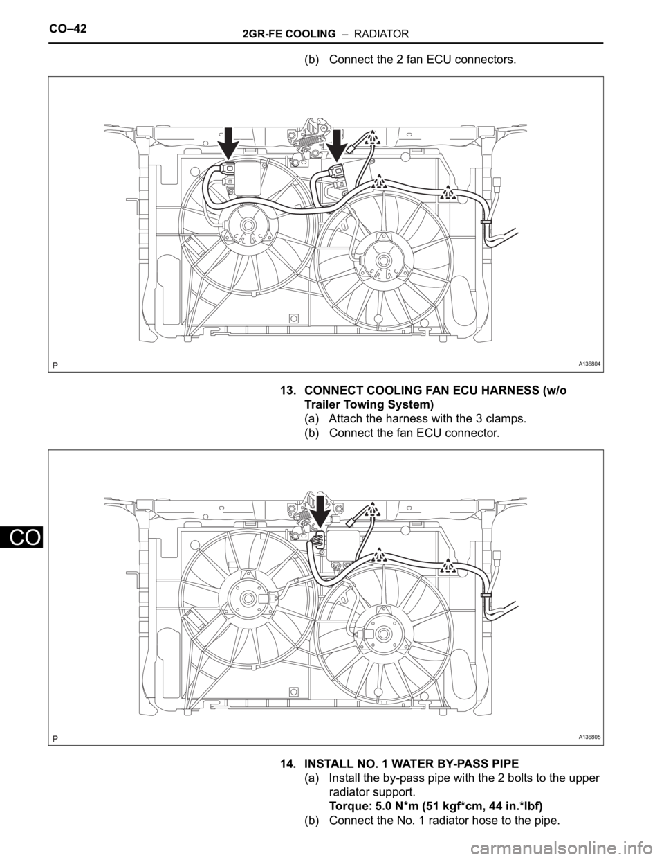
(b) Connect the 2 fan ECU connectors.
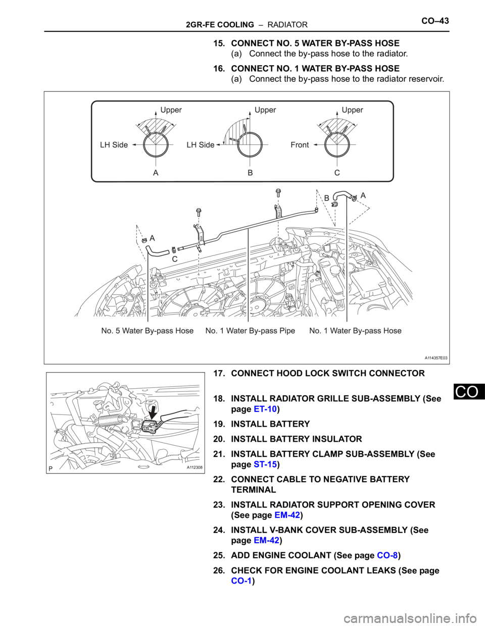
13. CONNECT COOLING FAN ECU HARNESS (w/o
Trailer Towing System)
(a) Attach the harness with the 3 clamps.
(b) Connect the fan ECU connector.
14. INSTALL NO. 1 WATER BY-PASS PIPE
(a) Install the by-pass pipe with the 2 bolts to the upper
radiator support.
Torque: 5.0 N*m (51 kgf*cm, 44 in.*lbf)
(b) Connect the No. 1 radiator hose to the pipe.
A136804
A136805
Page 872 of 2000
2GR-FE COOLING – RADIATORCO–43
CO
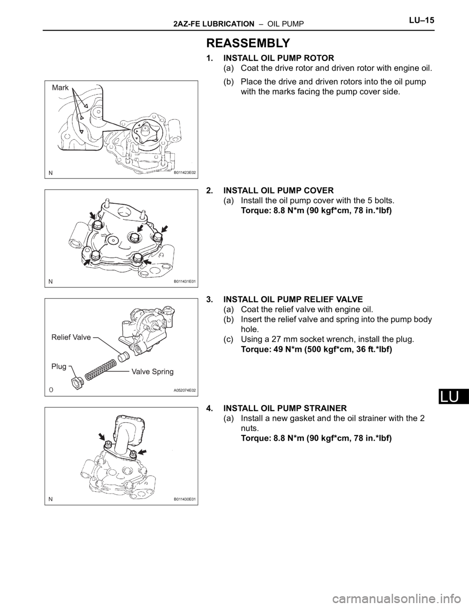
15. CONNECT NO. 5 WATER BY-PASS HOSE
(a) Connect the by-pass hose to the radiator.
16. CONNECT NO. 1 WATER BY-PASS HOSE
(a) Connect the by-pass hose to the radiator reservoir.
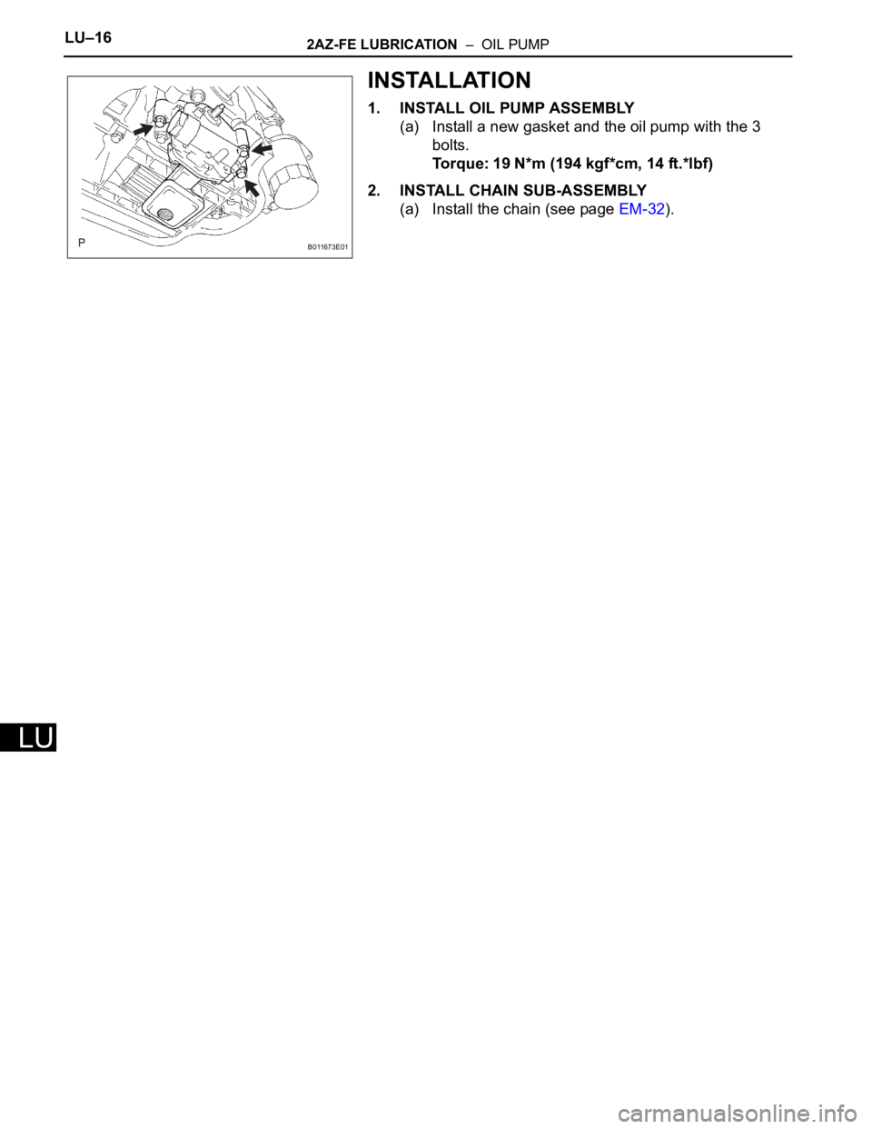
17. CONNECT HOOD LOCK SWITCH CONNECTOR
18. INSTALL RADIATOR GRILLE SUB-ASSEMBLY (See
page ET-10)
19. INSTALL BATTERY
20. INSTALL BATTERY INSULATOR
21. INSTALL BATTERY CLAMP SUB-ASSEMBLY (See
page ST-15)
22. CONNECT CABLE TO NEGATIVE BATTERY
TERMINAL
23. INSTALL RADIATOR SUPPORT OPENING COVER
(See page EM-42)
24. INSTALL V-BANK COVER SUB-ASSEMBLY (See
page EM-42)
25. ADD ENGINE COOLANT (See page CO-8)
26. CHECK FOR ENGINE COOLANT LEAKS (See page
CO-1)
A114357E03
A112308
Page 873 of 2000
CO–442GR-FE COOLING – RADIATOR
CO
27. INSTALL NO. 1 ENGINE UNDER COVER (See page
EM-41)
Page 874 of 2000
2AZ-FE LUBRICATION – OIL PUMPLU–15
LU
REASSEMBLY
1. INSTALL OIL PUMP ROTOR
(a) Coat the drive rotor and driven rotor with engine oil.
(b) Place the drive and driven rotors into the oil pump
with the marks facing the pump cover side.
2. INSTALL OIL PUMP COVER
(a) Install the oil pump cover with the 5 bolts.
Torque: 8.8 N*m (90 kgf*cm, 78 in.*lbf)
3. INSTALL OIL PUMP RELIEF VALVE
(a) Coat the relief valve with engine oil.
(b) Insert the relief valve and spring into the pump body
hole.
(c) Using a 27 mm socket wrench, install the plug.
Torque: 49 N*m (500 kgf*cm, 36 ft.*lbf)
4. INSTALL OIL PUMP STRAINER
(a) Install a new gasket and the oil strainer with the 2
nuts.
Torque: 8.8 N*m (90 kgf*cm, 78 in.*lbf)
B011423E02
B011431E01
A052074E02
B011430E01
Page 875 of 2000
LU–162AZ-FE LUBRICATION – OIL PUMP
LU
INSTALLATION
1. INSTALL OIL PUMP ASSEMBLY
(a) Install a new gasket and the oil pump with the 3
bolts.
Torque: 19 N*m (194 kgf*cm, 14 ft.*lbf)
2. INSTALL CHAIN SUB-ASSEMBLY
(a) Install the chain (see page EM-32).
B011673E01
Page 876 of 2000
LU–162GR-FE LUBRICATION – OIL PUMP
LU
INSPECTION
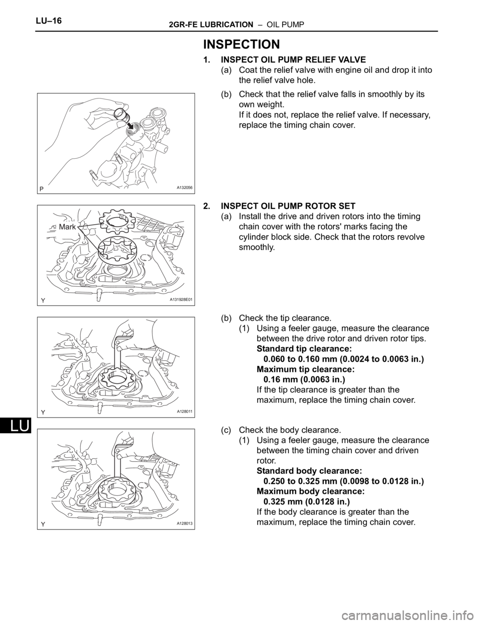
1. INSPECT OIL PUMP RELIEF VALVE
(a) Coat the relief valve with engine oil and drop it into
the relief valve hole.
(b) Check that the relief valve falls in smoothly by its
own weight.
If it does not, replace the relief valve. If necessary,
replace the timing chain cover.
2. INSPECT OIL PUMP ROTOR SET
(a) Install the drive and driven rotors into the timing
chain cover with the rotors' marks facing the
cylinder block side. Check that the rotors revolve
smoothly.
(b) Check the tip clearance.
(1) Using a feeler gauge, measure the clearance
between the drive rotor and driven rotor tips.
Standard tip clearance:
0.060 to 0.160 mm (0.0024 to 0.0063 in.)
Maximum tip clearance:
0.16 mm (0.0063 in.)
If the tip clearance is greater than the
maximum, replace the timing chain cover.
(c) Check the body clearance.
(1) Using a feeler gauge, measure the clearance
between the timing chain cover and driven
rotor.
Standard body clearance:
0.250 to 0.325 mm (0.0098 to 0.0128 in.)
Maximum body clearance:
0.325 mm (0.0128 in.)
If the body clearance is greater than the
maximum, replace the timing chain cover.
A132056
A131928E01
A128011
A128013
Page 877 of 2000
2GR-FE LUBRICATION – OIL PUMPLU–17
LU
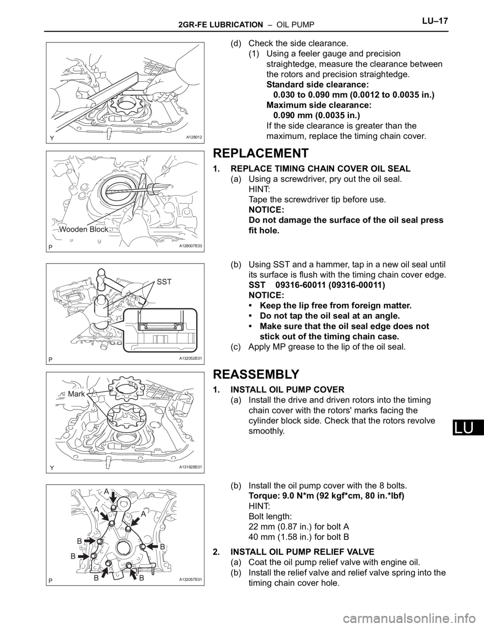
(d) Check the side clearance.
(1) Using a feeler gauge and precision
straightedge, measure the clearance between
the rotors and precision straightedge.
Standard side clearance:
0.030 to 0.090 mm (0.0012 to 0.0035 in.)
Maximum side clearance:
0.090 mm (0.0035 in.)
If the side clearance is greater than the
maximum, replace the timing chain cover.
REPLACEMENT
1. REPLACE TIMING CHAIN COVER OIL SEAL
(a) Using a screwdriver, pry out the oil seal.
HINT:
Tape the screwdriver tip before use.
NOTICE:
Do not damage the surface of the oil seal press
fit hole.
(b) Using SST and a hammer, tap in a new oil seal until
its surface is flush with the timing chain cover edge.
SST 09316-60011 (09316-00011)
NOTICE:
• Keep the lip free from foreign matter.
• Do not tap the oil seal at an angle.
• Make sure that the oil seal edge does not
stick out of the timing chain case.
(c) Apply MP grease to the lip of the oil seal.
REASSEMBLY
1. INSTALL OIL PUMP COVER
(a) Install the drive and driven rotors into the timing
chain cover with the rotors' marks facing the
cylinder block side. Check that the rotors revolve
smoothly.
(b) Install the oil pump cover with the 8 bolts.
Torque: 9.0 N*m (92 kgf*cm, 80 in.*lbf)
HINT:
Bolt length:
22 mm (0.87 in.) for bolt A
40 mm (1.58 in.) for bolt B
2. INSTALL OIL PUMP RELIEF VALVE
(a) Coat the oil pump relief valve with engine oil.
(b) Install the relief valve and relief valve spring into the
timing chain cover hole.
A128012
A128007E03
A132052E01
A131928E01
A132057E01
Page 878 of 2000
LU–182GR-FE LUBRICATION – OIL PUMP
LU
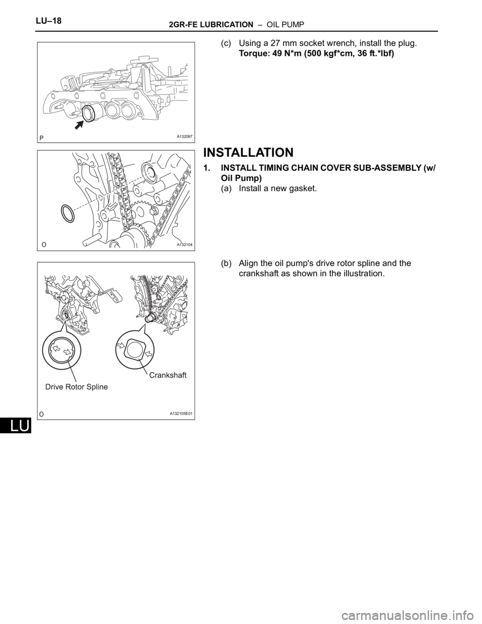
(c) Using a 27 mm socket wrench, install the plug.
Torque: 49 N*m (500 kgf*cm, 36 ft.*lbf)
INSTALLATION
1. INSTALL TIMING CHAIN COVER SUB-ASSEMBLY (w/
Oil Pump)
(a) Install a new gasket.
(b) Align the oil pump's drive rotor spline and the
crankshaft as shown in the illustration.
A132097
A132104
A132105E01
Page 879 of 2000
2GR-FE LUBRICATION – OIL PUMPLU–19
LU
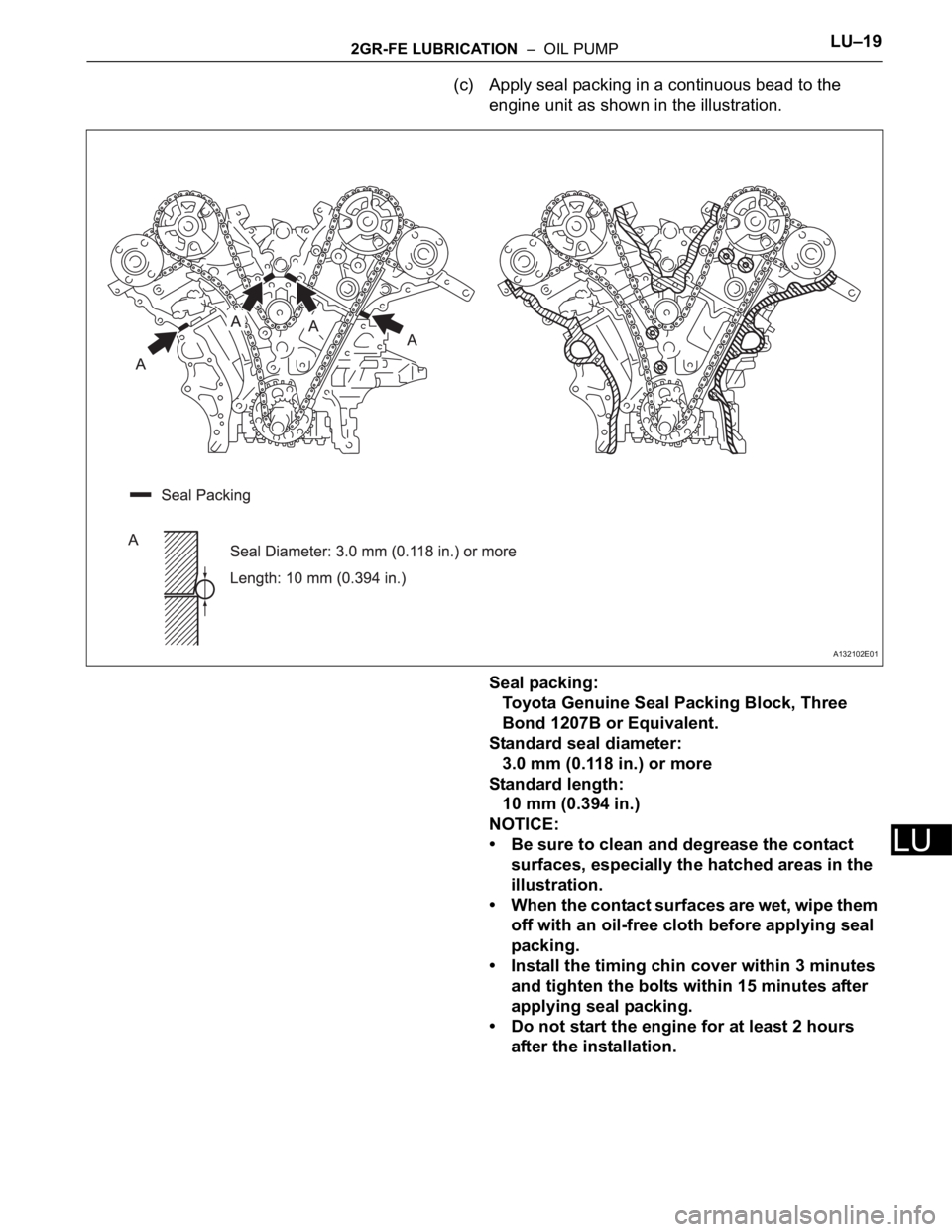
(c) Apply seal packing in a continuous bead to the
engine unit as shown in the illustration.
Seal packing:
Toyota Genuine Seal Packing Block, Three
Bond 1207B or Equivalent.
Standard seal diameter:
3.0 mm (0.118 in.) or more
Standard length:
10 mm (0.394 in.)
NOTICE:
• Be sure to clean and degrease the contact
surfaces, especially the hatched areas in the
illustration.
• When the contact surfaces are wet, wipe them
off with an oil-free cloth before applying seal
packing.
• Install the timing chin cover within 3 minutes
and tighten the bolts within 15 minutes after
applying seal packing.
• Do not start the engine for at least 2 hours
after the installation.
A132102E01
Page 880 of 2000
LU–202GR-FE LUBRICATION – OIL PUMP
LU
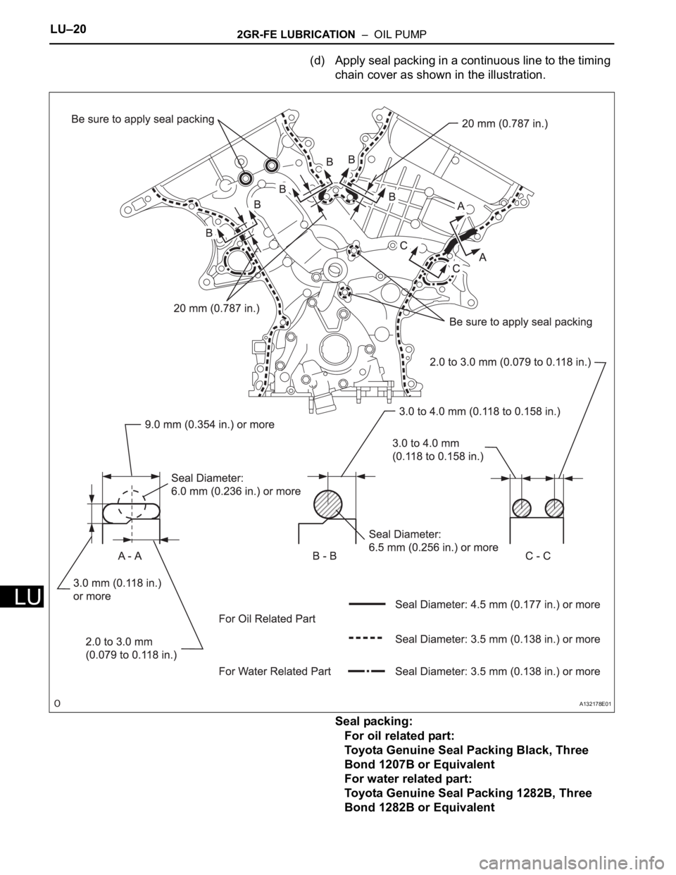
(d) Apply seal packing in a continuous line to the timing
chain cover as shown in the illustration.
Seal packing:
For oil related part:
Toyota Genuine Seal Packing Black, Three
Bond 1207B or Equivalent
For water related part:
Toyota Genuine Seal Packing 1282B, Three
Bond 1282B or Equivalent
A132178E01
Trending: diagnostic menu, drain bolt, transfer case, lubric, Crankshaft position sensor, 2GR FE, hood open
