ECU TOYOTA RAV4 PLUG-IN HYBRID 2023 Owner's Manual
[x] Cancel search | Manufacturer: TOYOTA, Model Year: 2023, Model line: RAV4 PLUG-IN HYBRID, Model: TOYOTA RAV4 PLUG-IN HYBRID 2023Pages: 718, PDF Size: 167.55 MB
Page 62 of 718
601-2. Child safety
*: Be sure to attach the seat belt through the SecureGuard.
The child restraint systems mentioned in the table may not be available out-
side the EU countries and United Kingdom.
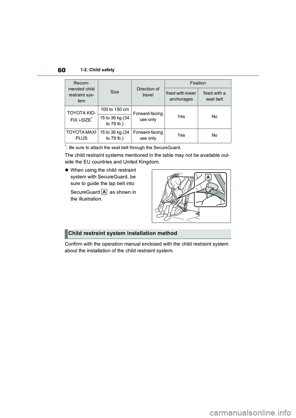
When using the child restraint
system with SecureGuard, be
sure to guide the lap belt into
SecureGuard as shown in
the illustration.
Confirm with the operation manual enclosed with the child restraint system
about the installation of the child restraint system.
TOYOTA KID-
FIX i-SIZE*
100 to 150 cmForward-facing
use onlyYesNo15 to 36 kg (34
to 79 lb.)
TOYOTA MAXI
PLUS
15 to 36 kg (34
to 79 lb.)
Forward-facing
use onlyYesNo
Recom-
mended child
restraint sys-
tem
SizeDirection of
travel
Fixation
fixed with lower
anchorages
fixed with a
seat belt
A
Child restraint system installation method
Page 63 of 718
61
1
1-2. Child safety
For safety and security
■Installing child restraint sys-
tem using a seat belt
Install the child restraint system in
accordance to the operation man-
ual enclosed with the child restraint
system.
If the child restraint system on hand
is not within the “universal” cate-
gory (or the necessary information
is not in the table), refer to the
“Vehicle List” provided by the child
restraint system maker for various
possible installation positions, or
check the compatibility after asking
the retailer of the child seat.
( P.55, 56)
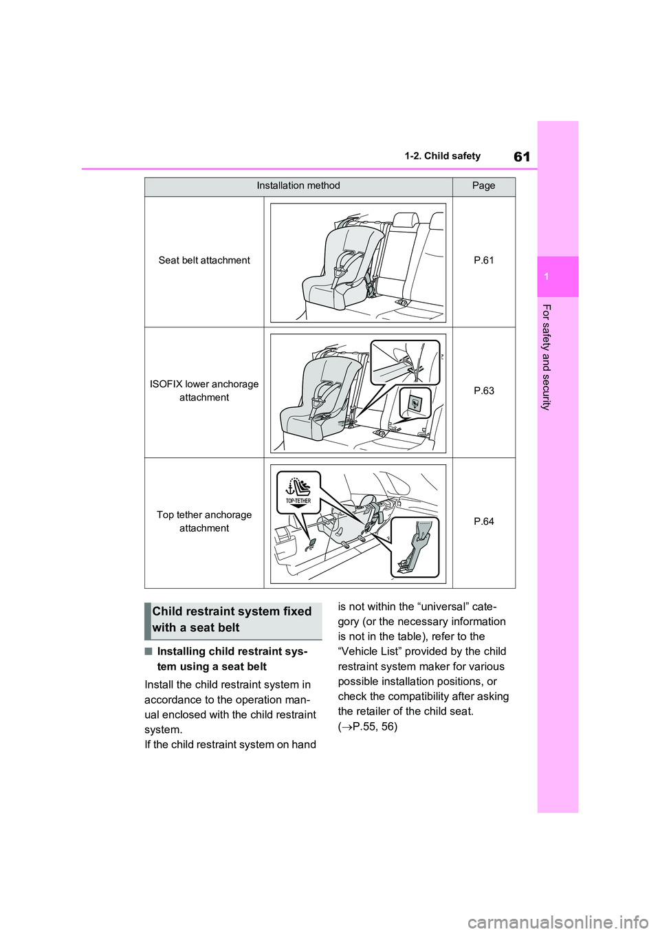
Installation methodPage
Seat belt attachmentP.61
ISOFIX lower anchorage
attachmentP.63
Top tether anchorage
attachmentP.64
Child restraint system fixed
with a seat belt
Page 64 of 718
621-2. Child safety
1If installing the child restraint
system to the front passenger
seat is unavoidable, refer to
P.52 for the front passenger
seat adjustment.
2 Adjust the seatback angle to the
most upright position. When
installing a forward-facing child
seat, if there is a gap between
the child seat and the seatback,
adjust the seatback angle until
good contact is achieved.
3 If the head restraint interferes
with the child restraint system
installation and the head
restraint can be removed,
remove the head restraint. Oth-
erwise, put the head restraint in
the upper most position.
( P.264)
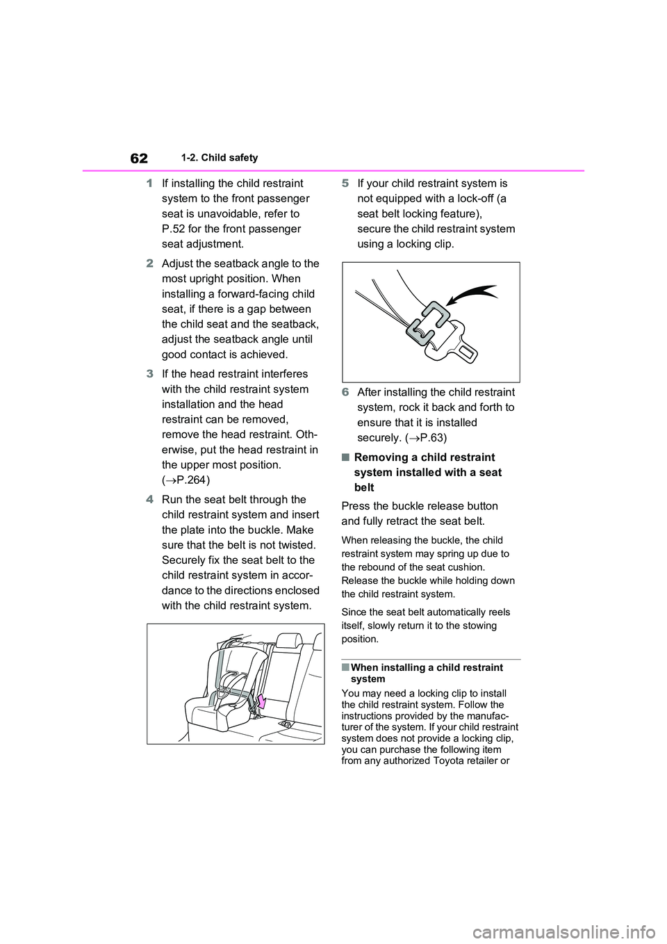
4 Run the seat belt through the
child restraint system and insert
the plate into the buckle. Make
sure that the belt is not twisted.
Securely fix the seat belt to the
child restraint system in accor-
dance to the directions enclosed
with the child restraint system.
5 If your child restraint system is
not equipped with a lock-off (a
seat belt locking feature),
secure the child restraint system
using a locking clip.
6 After installing the child restraint
system, rock it back and forth to
ensure that it is installed
securely. ( P.63)
■Removing a child restraint
system installed with a seat
belt
Press the buckle release button
and fully retract the seat belt.
When releasing the buckle, the child
restraint system may spring up due to
the rebound of the seat cushion.
Release the buckle while holding down
the child restraint system.
Since the seat belt automatically reels
itself, slowly return it to the stowing
position.
■When installing a child restraint
system
You may need a locking clip to install the child restraint system. Follow the
instructions provided by the manufac- turer of the system. If your child restraint system does not provide a locking clip,
you can purchase the following item from any authorized Toyota retailer or
Page 65 of 718
63
1
1-2. Child safety
For safety and security
Toyota authorized repairer, or any reli-
able repairer: Locking clip for child restraint system(Part No. 73119-22010)
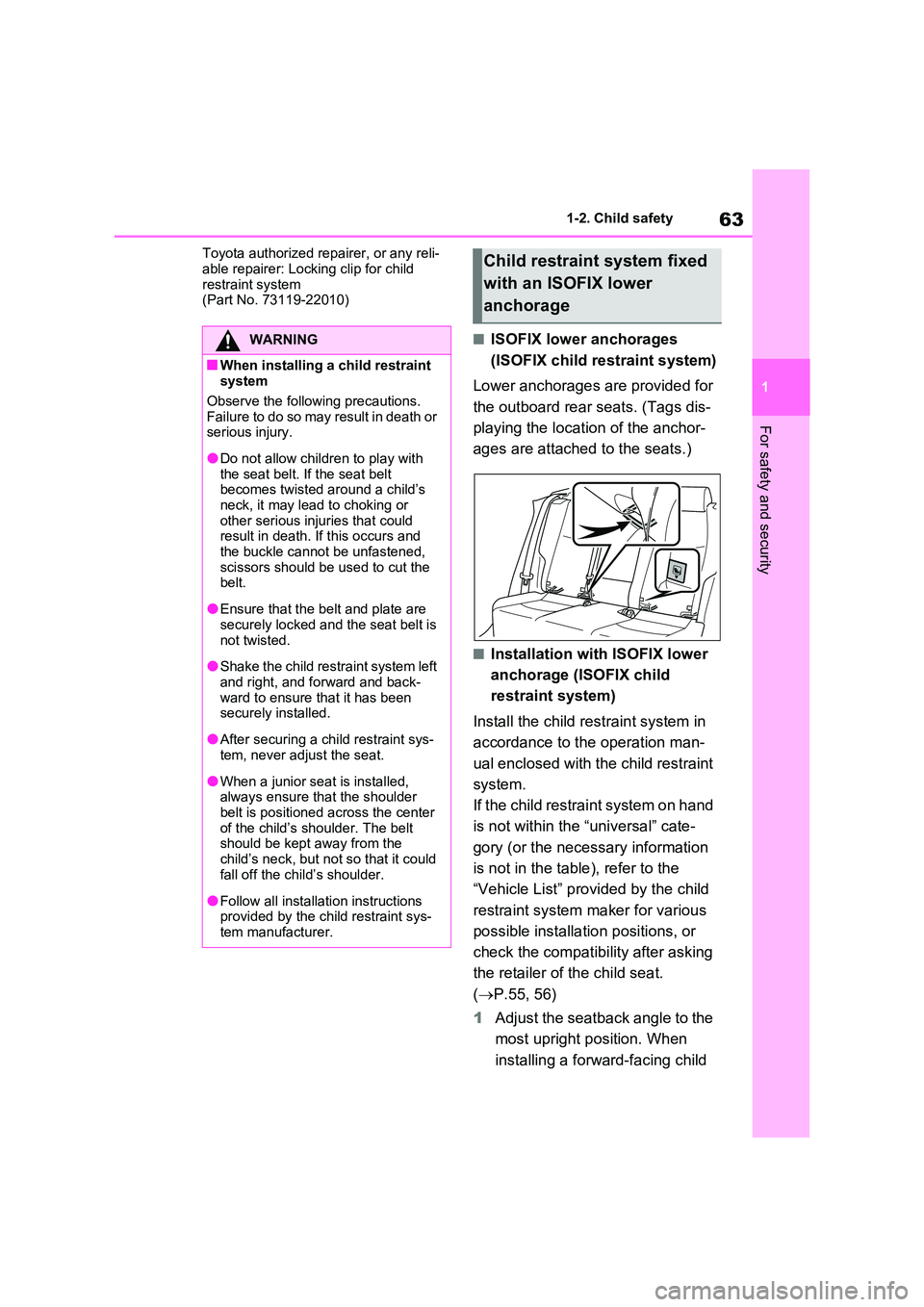
■ISOFIX lower anchorages
(ISOFIX child restraint system)
Lower anchorages are provided for
the outboard rear seats. (Tags dis-
playing the location of the anchor-
ages are attached to the seats.)
■Installation with ISOFIX lower
anchorage (ISOFIX child
restraint system)
Install the child restraint system in
accordance to the operation man-
ual enclosed with the child restraint
system.
If the child restraint system on hand
is not within the “universal” cate-
gory (or the necessary information
is not in the table), refer to the
“Vehicle List” provided by the child
restraint system maker for various
possible installation positions, or
check the compatibility after asking
the retailer of the child seat.
( P.55, 56)
1 Adjust the seatback angle to the
most upright position. When
installing a forward-facing child
WARNING
■When installing a child restraint system
Observe the following precautions.
Failure to do so may result in death or serious injury.
●Do not allow children to play with the seat belt. If the seat belt becomes twisted around a child’s
neck, it may lead to choking or other serious injuries that could result in death. If this occurs and
the buckle cannot be unfastened, scissors should be used to cut the belt.
●Ensure that the belt and plate are securely locked and the seat belt is
not twisted.
●Shake the child restraint system left
and right, and forward and back- ward to ensure that it has been securely installed.
●After securing a child restraint sys-tem, never adjust the seat.
●When a junior seat is installed, always ensure that the shoulder
belt is positioned across the center of the child’s shoulder. The belt should be kept away from the
child’s neck, but not so that it could fall off the child’s shoulder.
●Follow all installation instructions provided by the child restraint sys-tem manufacturer.
Child restraint system fixed
with an ISOFIX lower
anchorage
Page 66 of 718
641-2. Child safety
seat, if there is a gap between
the child seat and the seatback,
adjust the seatback angle until
good contact is achieved.
2 If the head restraint interferes
with the child restraint system
installation and the head
restraint can be removed,
remove the head restraint. Oth-
erwise, put the head restraint in
the upper most position.
( P.264)
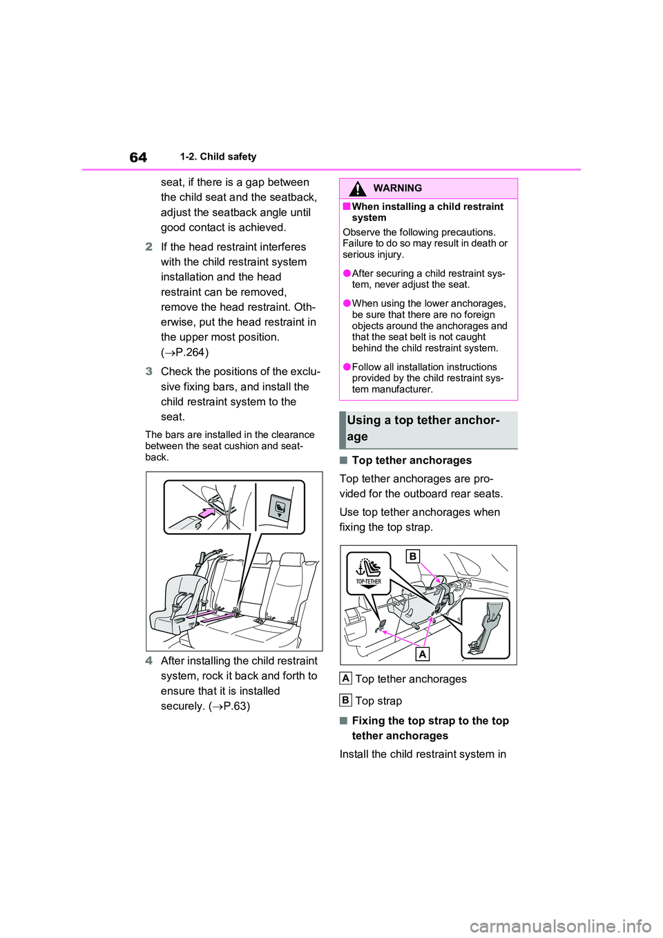
3 Check the positions of the exclu-
sive fixing bars, and install the
child restraint system to the
seat.
The bars are installed in the clearance between the seat cushion and seat-
back.
4 After installing the child restraint
system, rock it back and forth to
ensure that it is installed
securely. ( P.63)
■Top tether anchorages
Top tether anchorages are pro-
vided for the outboard rear seats.
Use top tether anchorages when
fixing the top strap.
Top tether anchorages
Top strap
■Fixing the top strap to the top
tether anchorages
Install the child restraint system in
WARNING
■When installing a child restraint system
Observe the following precautions. Failure to do so may result in death or serious injury.
●After securing a child restraint sys-tem, never adjust the seat.
●When using the lower anchorages, be sure that there are no foreign
objects around the anchorages and that the seat belt is not caught behind the child restraint system.
●Follow all installation instructions provided by the child restraint sys-
tem manufacturer.
Using a top tether anchor-
age
A
B
Page 67 of 718
65
1
1-2. Child safety
For safety and security
accordance to the operation man-
ual enclosed with the child restraint
system.
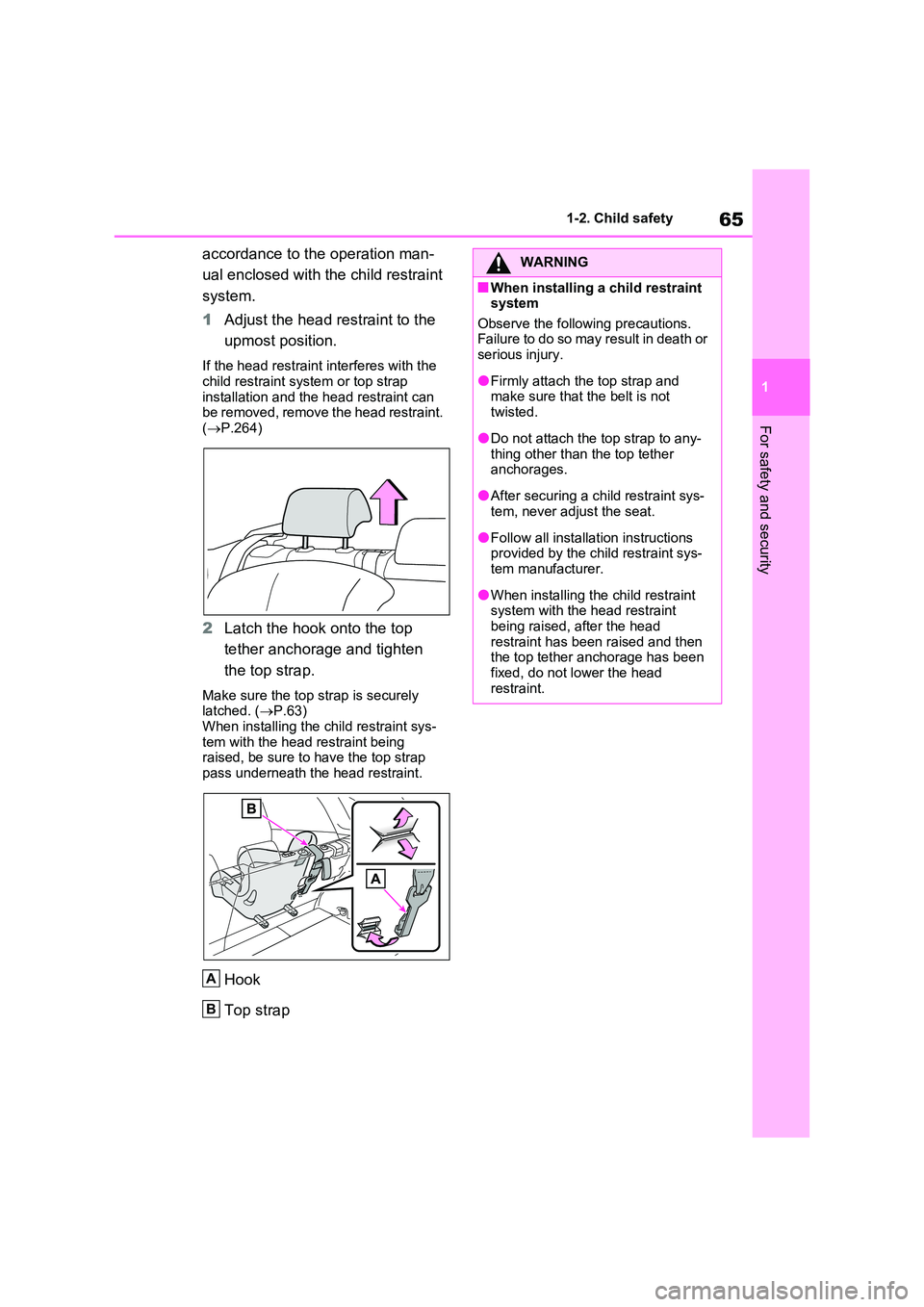
1 Adjust the head restraint to the
upmost position.
If the head restraint interferes with the
child restraint system or top strap installation and the head restraint can be removed, remove the head restraint.
( P.264)
2Latch the hook onto the top
tether anchorage and tighten
the top strap.
Make sure the top strap is securely latched. ( P.63)
When installing the child restraint sys- tem with the head restraint being raised, be sure to have the top strap
pass underneath the head restraint.
Hook
Top strap
A
B
WARNING
■When installing a child restraint system
Observe the following precautions. Failure to do so may result in death or serious injury.
●Firmly attach the top strap and make sure that the belt is not
twisted.
●Do not attach the top strap to any-
thing other than the top tether anchorages.
●After securing a child restraint sys-tem, never adjust the seat.
●Follow all installation instructions provided by the child restraint sys-tem manufacturer.
●When installing the child restraint system with the head restraint
being raised, after the head restraint has been raised and then the top tether anchorage has been
fixed, do not lower the head restraint.
Page 69 of 718
67
1
1-3. Emergency assistance
For safety and security
*: This button is intended for communi-
cation with the eCall system operator.
Other SOS buttons available in other
systems of a motor vehicle do not
relate to the device and are not
intended for communication with the
eCall system operator.
■Automatic Emergency Calls
If any airbag deploys, the system is
designed to automatically call the
eCall control center.* The answer-
ing operator receives the vehicle’s
location, the time of the incident
and the vehicle VIN, and attempts
to speak with the vehicle occupants
to assess the situation. If the occu-
pants are unable to communicate,
the operator automatically treats
the call as an emergency and con-
tacts the nearest emergency ser-
vices provider (112 system etc.) to
describe the situation and request
that assistance be sent to the loca-
tion.
*: In some cases, the call cannot be
made. ( P.68)
■Manual Emergency Calls
In the event of an emergency,
press the “SOS” button to call the
eCall control center.* The answer-
ing operator will determine your
vehicle’s location, assess the situa-
tion, and dispatch the necessary
assistance required.
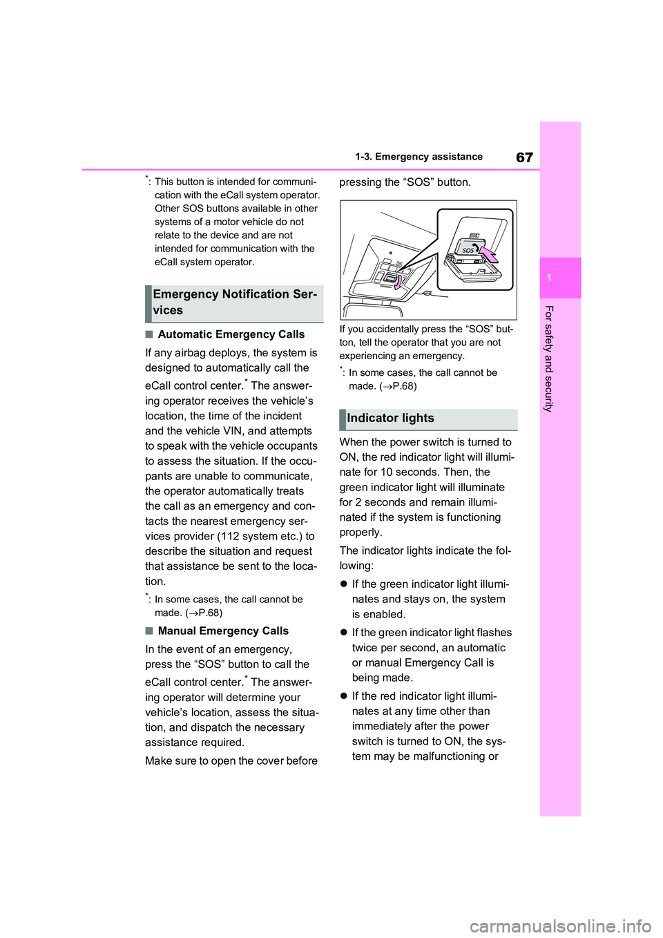
Make sure to open the cover before
pressing the “SOS” button.
If you accidentally press the “SOS” but-
ton, tell the operator that you are not
experiencing an emergency.
*: In some cases, the call cannot be
made. ( P.68)
When the power switch is turned to
ON, the red indicator light will illumi-
nate for 10 seconds. Then, the
green indicator light will illuminate
for 2 seconds and remain illumi-
nated if the system is functioning
properly.
The indicator lights indicate the fol-
lowing:
If the green indicator light illumi-
nates and stays on, the system
is enabled.
If the green indicator light flashes
twice per second, an automatic
or manual Emergency Call is
being made.
If the red indicator light illumi-
nates at any time other than
immediately after the power
switch is turned to ON, the sys-
tem may be malfunctioning or
Emergency Notification Ser-
vices
Indicator lights
Page 71 of 718
69
1
1-3. Emergency assistance
For safety and security
WARNING
●If the airbags deploy when the sys- tem is operating normally, the sys-
tem makes emergency call. The system also makes emergency call when the vehicle is struck from the
rear or rolls over, even if the air- bags do not deploy.
●For safety, do not make the Emer-gency Call while driving.Making calls during driving may
cause mishandling of the steering wheel, which may lead to unex-pected accidents.
Stop the vehicle and confirm the safety of your surroundings before making the Emergency Call.
●When changing fuses, please use the specified fuses. Using other
fuses may cause ignition or smoke in the circuit and lead to a fire.
●Using the system while there is smoke or an unusual smell may cause a fire. Stop using the system
immediately and consult any autho- rized Toyota retailer or Toyota authorized repairer, or any reliable
repairer.
NOTICE
■To prevent damage
Do not pour any liquids onto the “SOS” button panel, etc. and do not impact it.
■If the “SOS” button panel, speaker or microphone malfunc-
tions during an Emergency Call or manual maintenance check
It may not be possible to make Emer-
gency Calls, confirm the system sta- tus, or communicate with the eCall control center operator. If any of the
above equipment is damaged, please consult any authorized Toyota retailer or Toyota authorized repairer, or any
reliable repairer.
Page 73 of 718
71
1
1-3. Emergency assistance
For safety and security
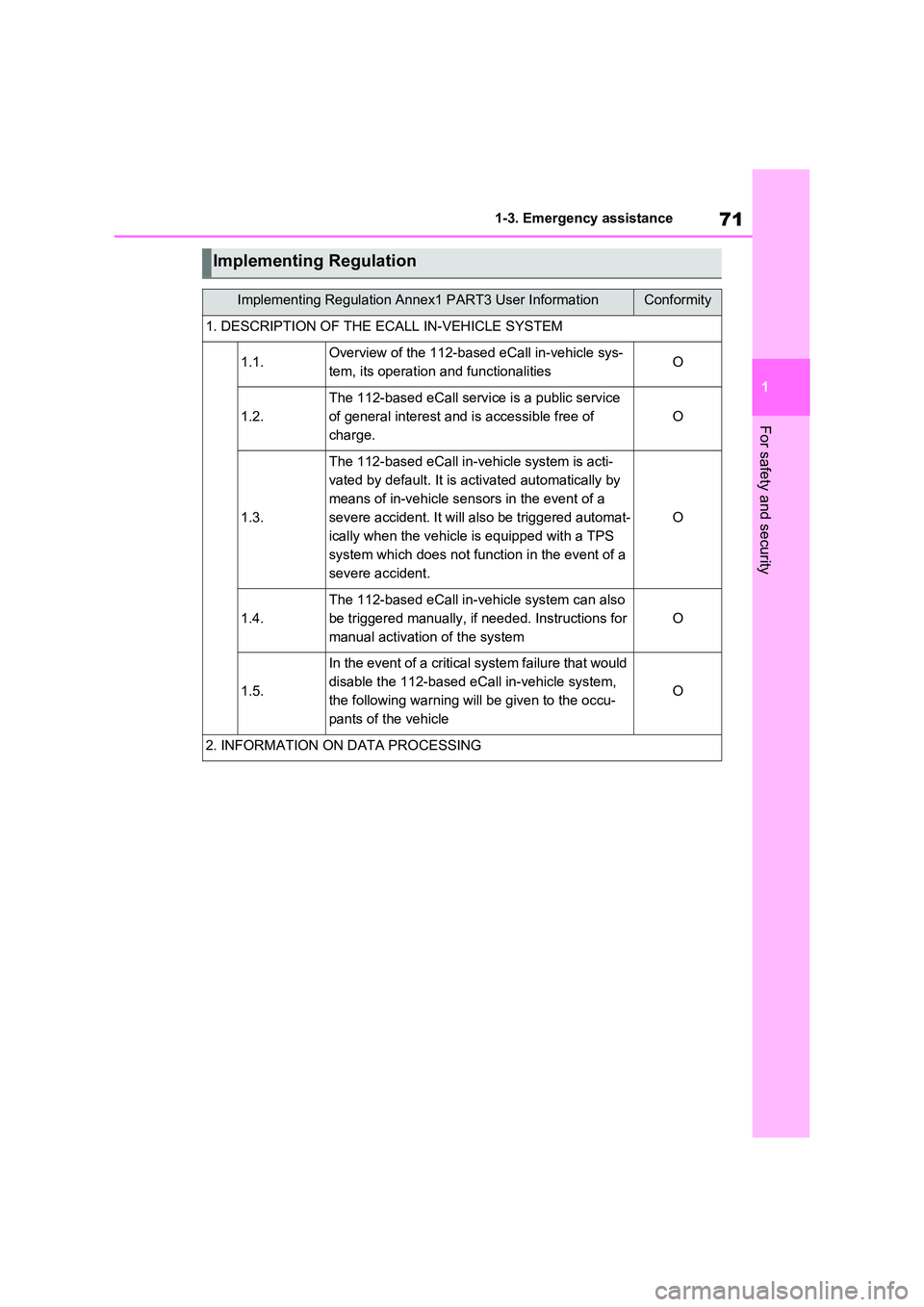
Implementing Regulation
Implementing Regulation Annex1 PART3 User InformationConformity
1. DESCRIPTION OF THE ECALL IN-VEHICLE SYSTEM
1.1.Overview of the 112-based eCall in-vehicle sys-
tem, its operation and functionalitiesO
1.2.
The 112-based eCall service is a public service
of general interest and is accessible free of
charge.
O
1.3.
The 112-based eCall in-vehicle system is acti-
vated by default. It is activated automatically by
means of in-vehicle sensors in the event of a
severe accident. It will also be triggered automat-
ically when the vehicle is equipped with a TPS
system which does not function in the event of a
severe accident.
O
1.4.
The 112-based eCall in-vehicle system can also
be triggered manually, if needed. Instructions for
manual activation of the system
O
1.5.
In the event of a critical system failure that would
disable the 112-based eCall in-vehicle system,
the following warning will be given to the occu-
pants of the vehicle
O
2. INFORMATION ON DATA PROCESSING
Page 75 of 718
73
1
1-3. Emergency assistance
For safety and security
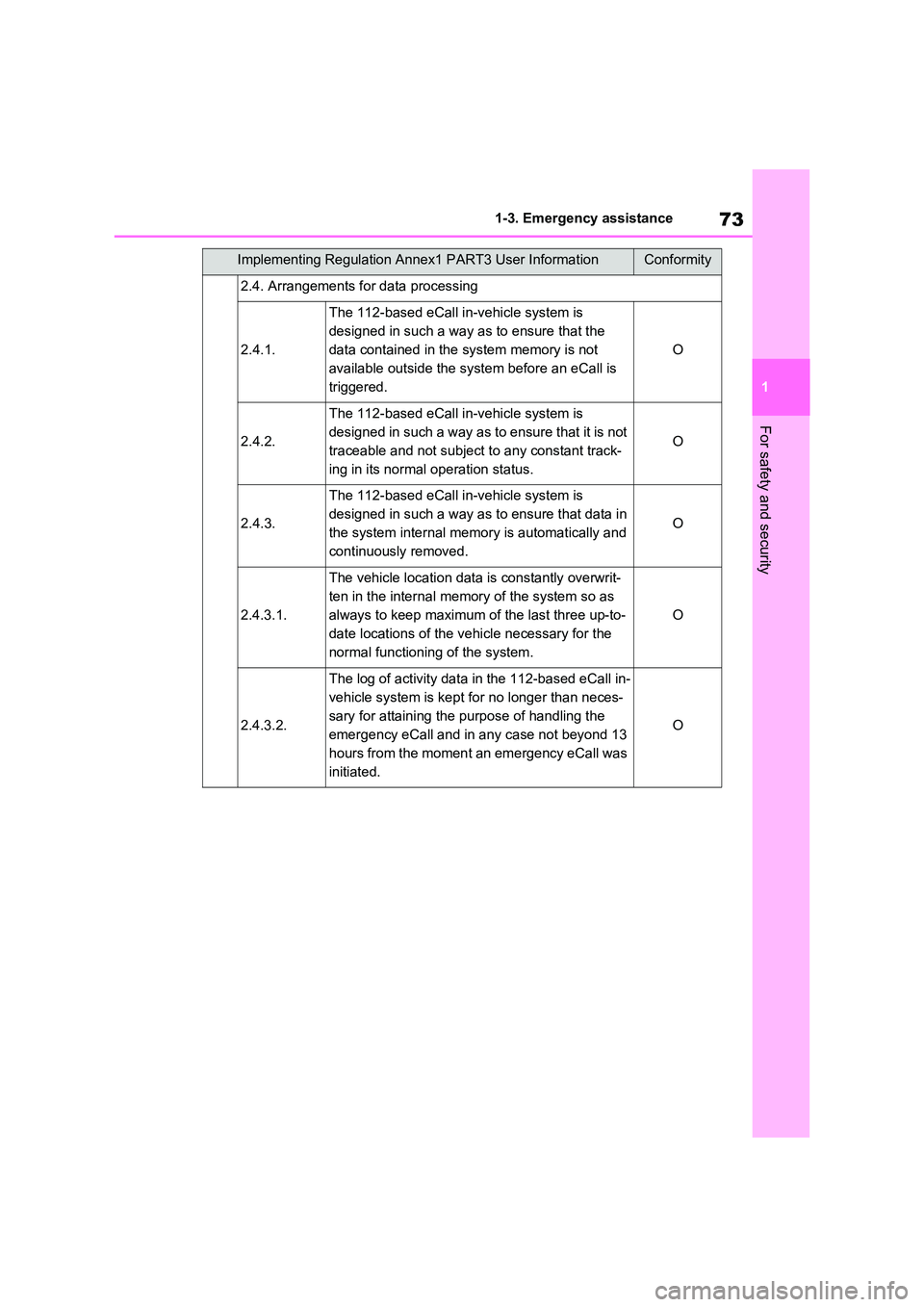
2.4. Arrangements for data processing
2.4.1.
The 112-based eCall in-vehicle system is
designed in such a way as to ensure that the
data contained in the system memory is not
available outside the system before an eCall is
triggered.
O
2.4.2.
The 112-based eCall in-vehicle system is
designed in such a way as to ensure that it is not
traceable and not subject to any constant track-
ing in its normal operation status.
O
2.4.3.
The 112-based eCall in-vehicle system is
designed in such a way as to ensure that data in
the system internal memory is automatically and
continuously removed.
O
2.4.3.1.
The vehicle location data is constantly overwrit-
ten in the internal memory of the system so as
always to keep maximum of the last three up-to-
date locations of the vehicle necessary for the
normal functioning of the system.
O
2.4.3.2.
The log of activity data in the 112-based eCall in-
vehicle system is kept for no longer than neces-
sary for attaining the purpose of handling the
emergency eCall and in any case not beyond 13
hours from the moment an emergency eCall was
initiated.
O
Implementing Regulation Annex1 PART3 User InformationConformity