TOYOTA SIENNA 2007 Service Repair Manual
Manufacturer: TOYOTA, Model Year: 2007, Model line: SIENNA, Model: TOYOTA SIENNA 2007Pages: 3000, PDF Size: 52.26 MB
Page 231 of 3000
RS–14SUPPLEMENTAL RESTRAINT SYSTEM – AIRBAG SYSTEM
RS
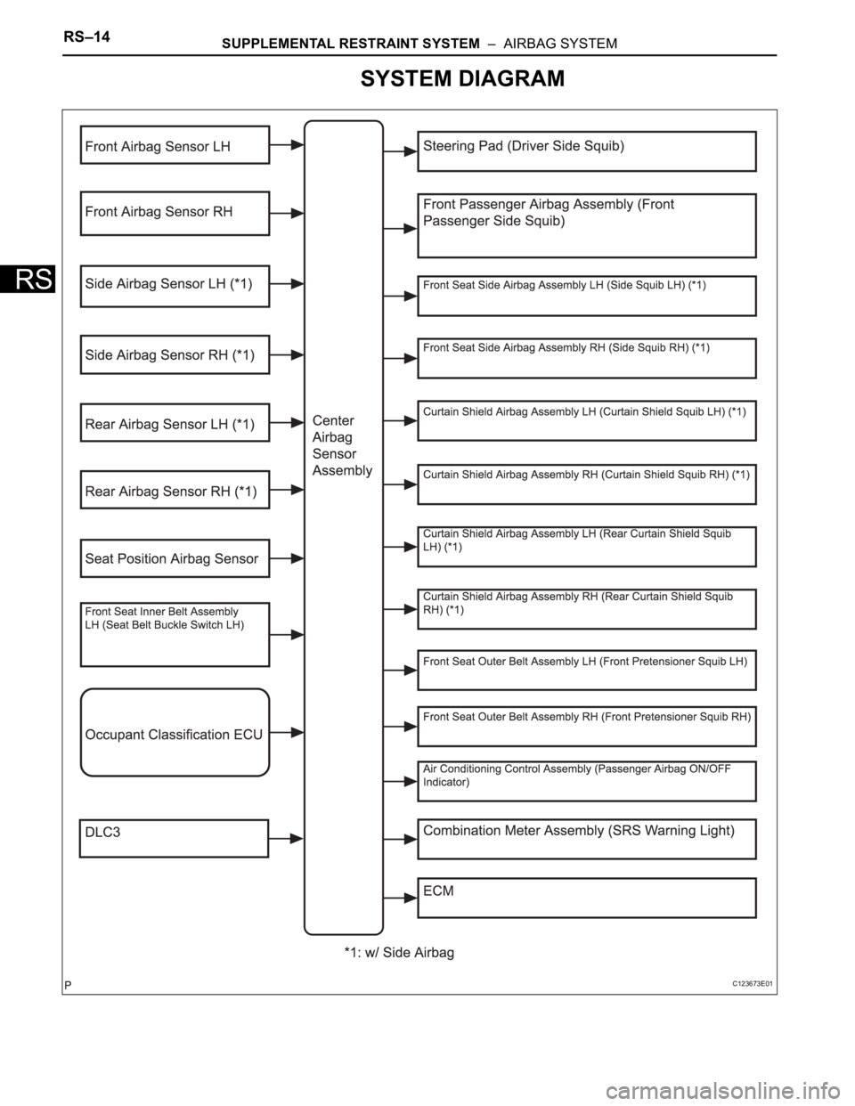
SYSTEM DIAGRAM
C123673E01
Page 232 of 3000
RS–474SUPPLEMENTAL RESTRAINT SYSTEM – SIDE AIRBAG SENSOR
RS
REMOVAL
HINT:
• Use the same procedures for the RH side and LH side.
• The procedures listed below are for the LH side.
1. PRECAUTION
CAUTION:
Be sure to read "PRECAUTION" thoroughly before
servicing (See page RS-1).
2. DISCONNECT CABLE FROM NEGATIVE BATTERY
TERMINAL
CAUTION:
Wait for 90 seconds after disconnecting the cable to
prevent the airbag working.
3. REMOVE FRONT DOOR SCUFF PLATE LH
HINT:
(See page IR-7)
4. REMOVE REAR DOOR SCUFF PLATE LH
HINT:
(See page IR-7)
5. REMOVE FRONT DOOR OPENING TRIM
WEATHERSTRIP LH
HINT:
(See page IR-7)
6. REMOVE REAR DOOR WEATHERSTRIP LH (See
page IR-7)
7. REMOVE LAP BELT OUTER ANCHOR COVER LH
8. REMOVE CENTER PILLAR GARNISH LOWER LH
(See page IR-8)
9. REMOVE FRONT SEAT OUTER BELT ASSEMBLY
(See page SB-7)
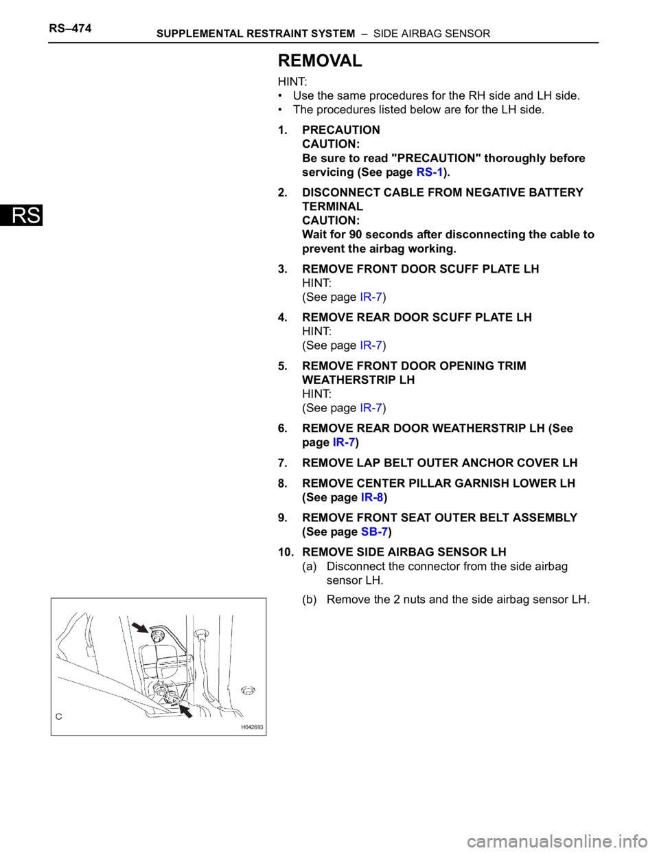
10. REMOVE SIDE AIRBAG SENSOR LH
(a) Disconnect the connector from the side airbag
sensor LH.
(b) Remove the 2 nuts and the side airbag sensor LH.
H042693
Page 233 of 3000
SUPPLEMENTAL RESTRAINT SYSTEM – SIDE AIRBAG SENSORRS–475
RS
INSTALLATION
HINT:
• Use the same procedures for the RH side and LH side.
• The procedures listed below are for the LH side.
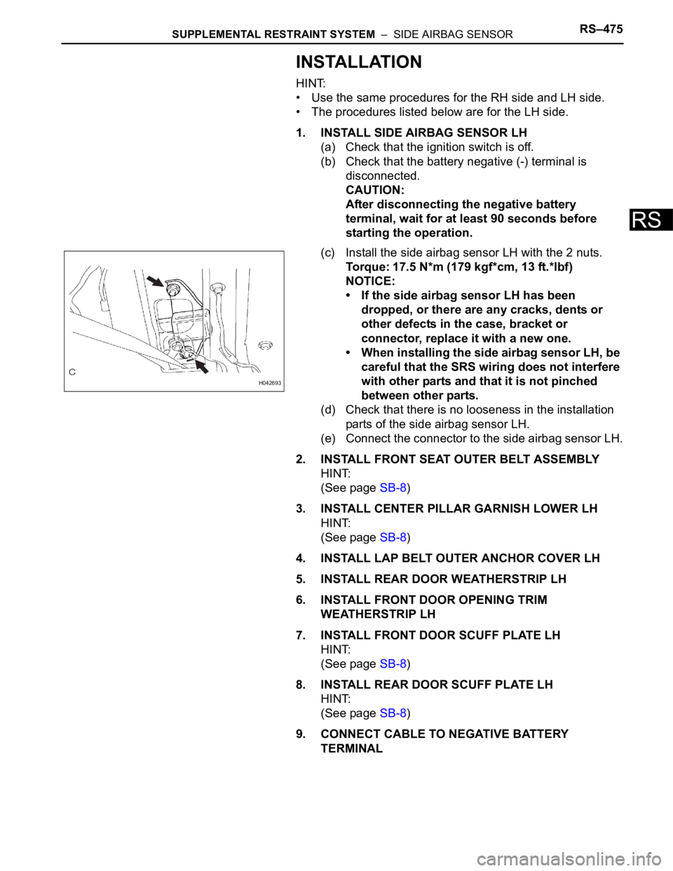
1. INSTALL SIDE AIRBAG SENSOR LH
(a) Check that the ignition switch is off.
(b) Check that the battery negative (-) terminal is
disconnected.
CAUTION:
After disconnecting the negative battery
terminal, wait for at least 90 seconds before
starting the operation.
(c) Install the side airbag sensor LH with the 2 nuts.
Torque: 17.5 N*m (179 kgf*cm, 13 ft.*lbf)
NOTICE:
• If the side airbag sensor LH has been
dropped, or there are any cracks, dents or
other defects in the case, bracket or
connector, replace it with a new one.
• When installing the side airbag sensor LH, be
careful that the SRS wiring does not interfere
with other parts and that it is not pinched
between other parts.
(d) Check that there is no looseness in the installation
parts of the side airbag sensor LH.
(e) Connect the connector to the side airbag sensor LH.
2. INSTALL FRONT SEAT OUTER BELT ASSEMBLY
HINT:
(See page SB-8)
3. INSTALL CENTER PILLAR GARNISH LOWER LH
HINT:
(See page SB-8)
4. INSTALL LAP BELT OUTER ANCHOR COVER LH
5. INSTALL REAR DOOR WEATHERSTRIP LH
6. INSTALL FRONT DOOR OPENING TRIM
WEATHERSTRIP LH
7. INSTALL FRONT DOOR SCUFF PLATE LH
HINT:
(See page SB-8)
8. INSTALL REAR DOOR SCUFF PLATE LH
HINT:
(See page SB-8)
9. CONNECT CABLE TO NEGATIVE BATTERY
TERMINAL
H042693
Page 234 of 3000

RS–476SUPPLEMENTAL RESTRAINT SYSTEM – SIDE AIRBAG SENSOR
RS
10. PERFORM INITIALIZATION
(a) Perform initialization.
HINT:
Some systems need initialization when
disconnecting the cable from the negative battery
terminal.
11. INSPECT SRS WARNING LIGHT
(a) Inspect the SRS warning light (See page RS-27).
Page 235 of 3000

SB–6SEAT BELT – FRONT SEAT INNER BELT ASSEMBLY
SB
INSTALLATION
1. REMOVE FRONT SEAT INNER BELT ASSEMBLY
HINT:
• Refer to the instructions for reassembly of the front
seat assembly (for flat type) (See page SE-43).
• Refer to the instructions for reassembly of the front
seat assembly (for manual seat) (See page SE-52).
• Refer to the instructions for reassembly of the front
seat assembly (for power seat) (See page SE-62).
(a) Install the front seat inner belt assembly with the
nut.
Torque: 42 N*m (430 kgf*cm, 31 ft.*lbf)
Page 236 of 3000

THEFT DETERRENT – THEFT DETERRENT SYSTEMTD–3
TD
SYSTEM DESCRIPTION
1. OUTLINE OF THEFT DETERRENT SYSTEM
(a) When the theft deterrent system detects that the
vehicle is being tampered with, the system sets off
the alarm, causing the horns to sound and the lights
to light up or blink in order to alert people around the
vehicle to the theft.
(b) The theft deterrent system has 2 modes; one is the
active arming mode (see ACTIVE ARMING MODE)
and the other is passive arming mode (see
PASSIVE ARMING MODE). The passive arming
mode can be switched ON/OFF using the specified
method.
(c) Each mode has 4 states; a disarmed state, an
arming preparation state, an armed state and an
alarm sounding state.
(1) Disarmed state:
• The alarm function is not operating.
• The theft deterrent system is not operating.
(2) Arming preparation state:
• The time until the system goes into the armed
state.
• The theft deterrent system is not operating.
(3) Armed state:
• The theft deterrent system is operating.
(4) Alarm sounding state:
• Alarm function is operating.
Alarm time:
Approx. 60 sec.
Refer to table below for alarm method and time:
HINT:
If any of the doors are unlocked with no key in
the ignition key cylinder during the armed state,
a forced door lock signal will be output (see
FORCED DOOR LOCK CONTROL).
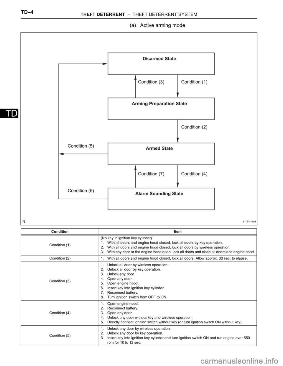
2. ACTIVE ARMING MODE
HINT:
• Active arming mode starts the alarm control
immediately after the doors are locked.
• This system activates as described in the diagram
below when one of items for each condition is met.
Alarm MethodHeadlight Blinking (approx. 0.4 second cycles)
Taillight Blinking (approx. 0.4 second cycles)
Hazard Warning Light Blinking (cycles of flasher relay)
Interior Light Illuminating
Vehicle HornSounding
(approx. 0.4 second cycles)
Security HornSounding
(approx. 0.4 second cycles)
Alarm Time Approx. 60 sec.
Page 237 of 3000
TD–4THEFT DETERRENT – THEFT DETERRENT SYSTEM
TD
(a) Active arming mode
Condition Item
Condition (1)(No key in ignition key cylinder)
1. With all doors and engine hood closed, lock all doors by key operation.
2. With all doors and engine hood closed, lock all doors by wireless operation.
3. With any door or the engine hood open, lock all doors and close all doors and engine hood.
Condition (2) 1. With all doors and engine hood closed, lock all doors. Allow approx. 30 sec. to elapse.
Condition (3)1. Unlock all door by wireless operation.
2. Unlock all door by key operation.
3. Unlock any door.
4. Open any door.
5. Open engine hood.
6. Insert key into ignition key cylinder.
7. Reconnect battery.
8. Turn ignition switch from OFF to ON.
Condition (4)1. Open engine hood.
2. Reconnect battery.
3. Open any door.
4. Unlock any door without key and wireless operation.
5. Directly connect ignition switch without key (or turn ignition switch ON without key).
Condition (5)1. Unlock any door by wireless operation.
2. Unlock any door by key operation.
3. Insert key into ignition key cylinder and turn ignition switch ON and run engine over 550
rpm for 10 to 12 sec.
B112141E04
Page 238 of 3000

THEFT DETERRENT – THEFT DETERRENT SYSTEMTD–5
TD
3. PASSIVE ARMING MODE
HINT:
• Passive arming mode starts the alarm control after
the key is removed from the ignition key cylinder and
doors are closed.
• Passive arming mode can be switched ON/OFF by
the specified method.
• The alarm is initially set (when shipped from factory)
to active arming mode (not passive arming mode).
• During passive arming mode, the theft deterrent
system goes into the armed state even if the doors
are not locked.
• Detecting that the doors are unlocked does not set off
the alarm during passive arming mode.
• A forced door lock signal is not output during passive
arming mode (see FORCED DOOR LOCK
CONTROL).
• Although the theft deterrent system detects that the
doors are opened during passive arming mode, the
alarm will not go off immediately because an entry
delay time is set.
• If any of the following conditions is met during passive
arming mode, the theft deterrent system will switch to
active arming mode.
– With all doors and engine hood closed, lock all
doors by key operation.
– With all doors and engine hood closed, lock all
doors by wireless operation.
– With any door or the engine hood open, lock all
doors and close all doors and engine hood.
• This system activates as described in the diagram
below when one of items for each condition is met.
Condition (6)1. Unlock any door by wireless operation.
2. Unlock any door by key operation.
3. Insert key into ignition key cylinder and turn ignition switch from OFF to ON.
Condition (7) 1. After approx. 60 sec., alarm stops and system returns to armed state. Condition Item
Page 239 of 3000
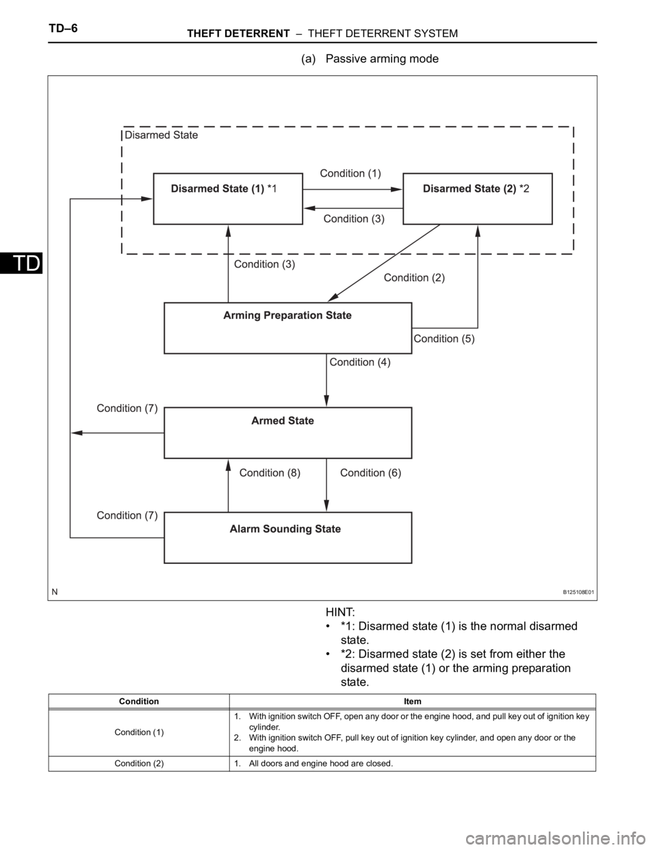
TD–6THEFT DETERRENT – THEFT DETERRENT SYSTEM
TD
(a) Passive arming mode
HINT:
• *1: Disarmed state (1) is the normal disarmed
state.
• *2: Disarmed state (2) is set from either the
disarmed state (1) or the arming preparation
state.
B125108E01
Condition Item
Condition (1)1. With ignition switch OFF, open any door or the engine hood, and pull key out of ignition key
cylinder.
2. With ignition switch OFF, pull key out of ignition key cylinder, and open any door or the
engine hood.
Condition (2) 1. All doors and engine hood are closed.
Page 240 of 3000

THEFT DETERRENT – THEFT DETERRENT SYSTEMTD–7
TDHINT:
*1: When any door is opened while all the doors are
closed during passive arming mode, the entry delay
time starts. If the switch condition (armed state
disarmed state (1) or (2)) is met during the entry
delay time, the theft deterrent system will return to
disarmed state (1) or (2). However, if the switch
condition for disarmed state (1) or (2) is not met, the
theft deterrent system will recognize it as a theft and
set off the alarm.
Entry delay time of 0, 14 or 30 sec. can be selected
by the customizing function.
4. FORCED DOOR LOCK CONTROL
(a) The forced door lock control prevents the vehicle
from being tampered with. Immediately after a door
is unlocked (alarm starts), the door is forced to lock
by a forced door lock signal.
(1) Conditions that force the doors to lock:
No key is in the ignition key cylinder and both of
the following conditions are met.
• The theft deterrent system is in the alarm
sounding state of active arming mode.
• Any door is unlocked.
Condition (3)1. Unlock all door by wireless operation.
2. Insert key into ignition key cylinder.
3. Reconnect battery.
4. Turn ignition switch from OFF to ON.
5. Unlock any door by key operation.
Condition (4) 1. With all doors and engine hood closed, allow approx. 30 sec. to elapse.
Condition (5) 1. Open any door or the engine hood.
Condition (6)1. Open any door and allow entry delay time
*1 to elapse.
2. Open engine hood.
3. Reconnect battery.
4. Directly connect ignition switch without key (or turn ignition switch ON without key).
Condition (7)1. Unlock all door by wireless operation.
2. Unlock all door by key operation.
3. Insert key into ignition key cylinder and turn ignition switch from OFF to ON.
Condition (8) 1. After approx. 60 sec., alarm stops and system returns to armed state. Condition Item