TOYOTA SIENNA 2007 Service Repair Manual
SIENNA 2007
TOYOTA
TOYOTA
https://www.carmanualsonline.info/img/14/57466/w960_57466-0.png
TOYOTA SIENNA 2007 Service Repair Manual
Trending: check engine light, traction control, wheel torque, inflation pressure, steering wheel adjustment, Strut, brakes
Page 261 of 3000
AV–200AUDIO / VISUAL – STEERING PAD SWITCH
AV
INSPECTION
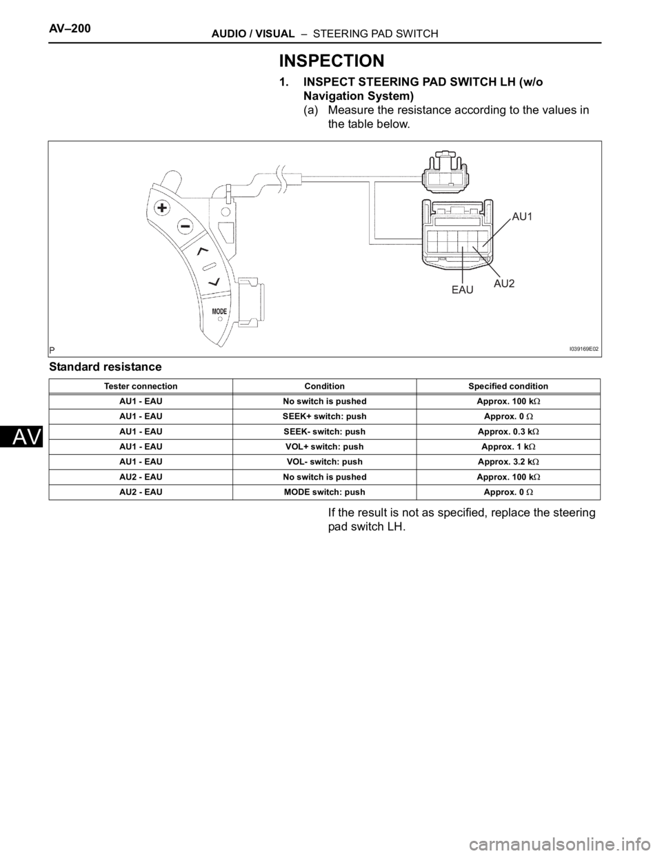
1. INSPECT STEERING PAD SWITCH LH (w/o
Navigation System)
(a) Measure the resistance according to the values in
the table below.
Standard resistance
If the result is not as specified, replace the steering
pad switch LH.
Tester connection Condition Specified condition
AU1 - EAU No switch is pushed Approx. 100 k
AU1 - EAU SEEK+ switch: push Approx. 0
AU1 - EAU SEEK- switch: push Approx. 0.3 k
AU1 - EAU VOL+ switch: push Approx. 1 k
AU1 - EAU VOL- switch: push Approx. 3.2 k
AU2 - EAU No switch is pushed Approx. 100 k
AU2 - EAU MODE switch: push Approx. 0
I039169E02
Page 262 of 3000
AUDIO / VISUAL – STEERING PAD SWITCHAV – 2 0 1
AV
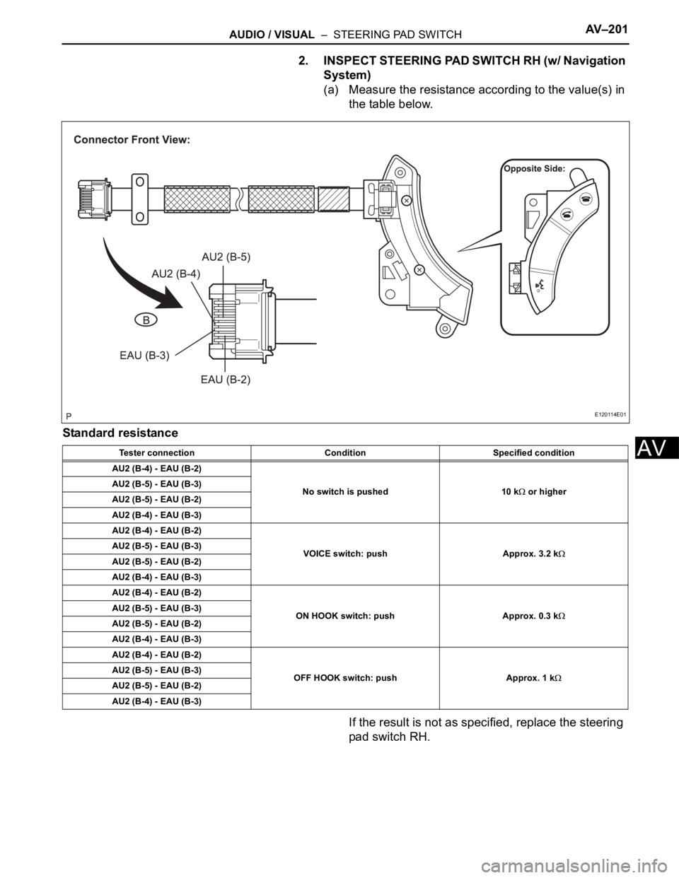
2. INSPECT STEERING PAD SWITCH RH (w/ Navigation
System)
(a) Measure the resistance according to the value(s) in
the table below.
Standard resistance
If the result is not as specified, replace the steering
pad switch RH.
Tester connection Condition Specified condition
AU2 (B-4) - EAU (B-2)
No switch is pushed 10 k
or higher AU2 (B-5) - EAU (B-3)
AU2 (B-5) - EAU (B-2)
AU2 (B-4) - EAU (B-3)
AU2 (B-4) - EAU (B-2)
VOICE switch: push Approx. 3.2 k
AU2 (B-5) - EAU (B-3)
AU2 (B-5) - EAU (B-2)
AU2 (B-4) - EAU (B-3)
AU2 (B-4) - EAU (B-2)
ON HOOK switch: push Approx. 0.3 k
AU2 (B-5) - EAU (B-3)
AU2 (B-5) - EAU (B-2)
AU2 (B-4) - EAU (B-3)
AU2 (B-4) - EAU (B-2)
OFF HOOK switch: push Approx. 1 k
AU2 (B-5) - EAU (B-3)
AU2 (B-5) - EAU (B-2)
AU2 (B-4) - EAU (B-3)
E120114E01
Page 263 of 3000
AV–202AUDIO / VISUAL – STEERING PAD SWITCH
AV
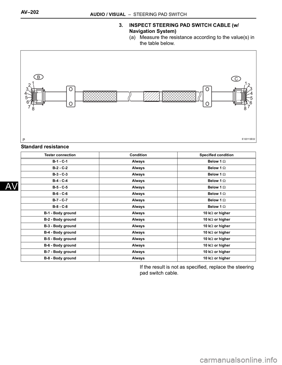
3. INSPECT STEERING PAD SWITCH CABLE (w/
Navigation System)
(a) Measure the resistance according to the value(s) in
the table below.
Standard resistance
If the result is not as specified, replace the steering
pad switch cable.
Tester connection Condition Specified condition
B-1 - C-1 Always Below 1
B-2 - C-2 Always Below 1
B-3 - C-3 Always Below 1
B-4 - C-4 Always Below 1
B-5 - C-5 Always Below 1
B-6 - C-6 Always Below 1
B-7 - C-7 Always Below 1
B-8 - C-8 Always Below 1
B-1 - Body ground Always 10 k or higher
B-2 - Body ground Always 10 k
or higher
B-3 - Body ground Always 10 k
or higher
B-4 - Body ground Always 10 k
or higher
B-5 - Body ground Always 10 k
or higher
B-6 - Body ground Always 10 k
or higher
B-7 - Body ground Always 10 k
or higher
B-8 - Body ground Always 10 k
or higher
E120113E02
Page 264 of 3000
NAVIGATION – NAVIGATION SYSTEMNS–3
NS
SYSTEM DESCRIPTION
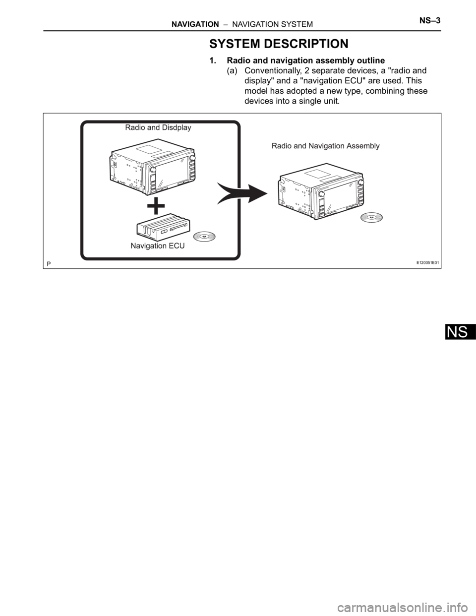
1. Radio and navigation assembly outline
(a) Conventionally, 2 separate devices, a "radio and
display" and a "navigation ECU" are used. This
model has adopted a new type, combining these
devices into a single unit.
E120051E01
Page 265 of 3000
NS–4NAVIGATION – NAVIGATION SYSTEM
NS
2. Navigation system outline
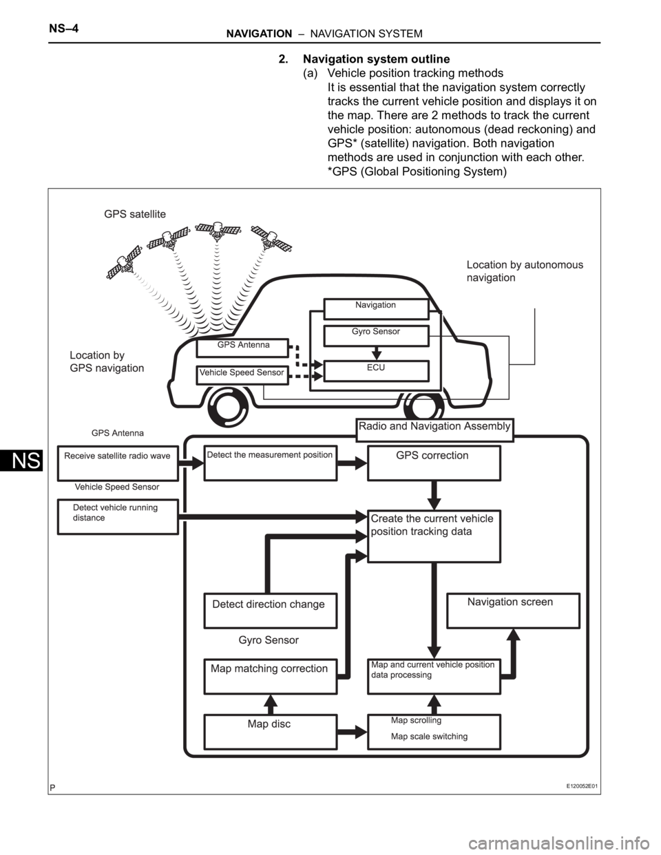
(a) Vehicle position tracking methods
It is essential that the navigation system correctly
tracks the current vehicle position and displays it on
the map. There are 2 methods to track the current
vehicle position: autonomous (dead reckoning) and
GPS* (satellite) navigation. Both navigation
methods are used in conjunction with each other.
*GPS (Global Positioning System)
E120052E01
Page 266 of 3000
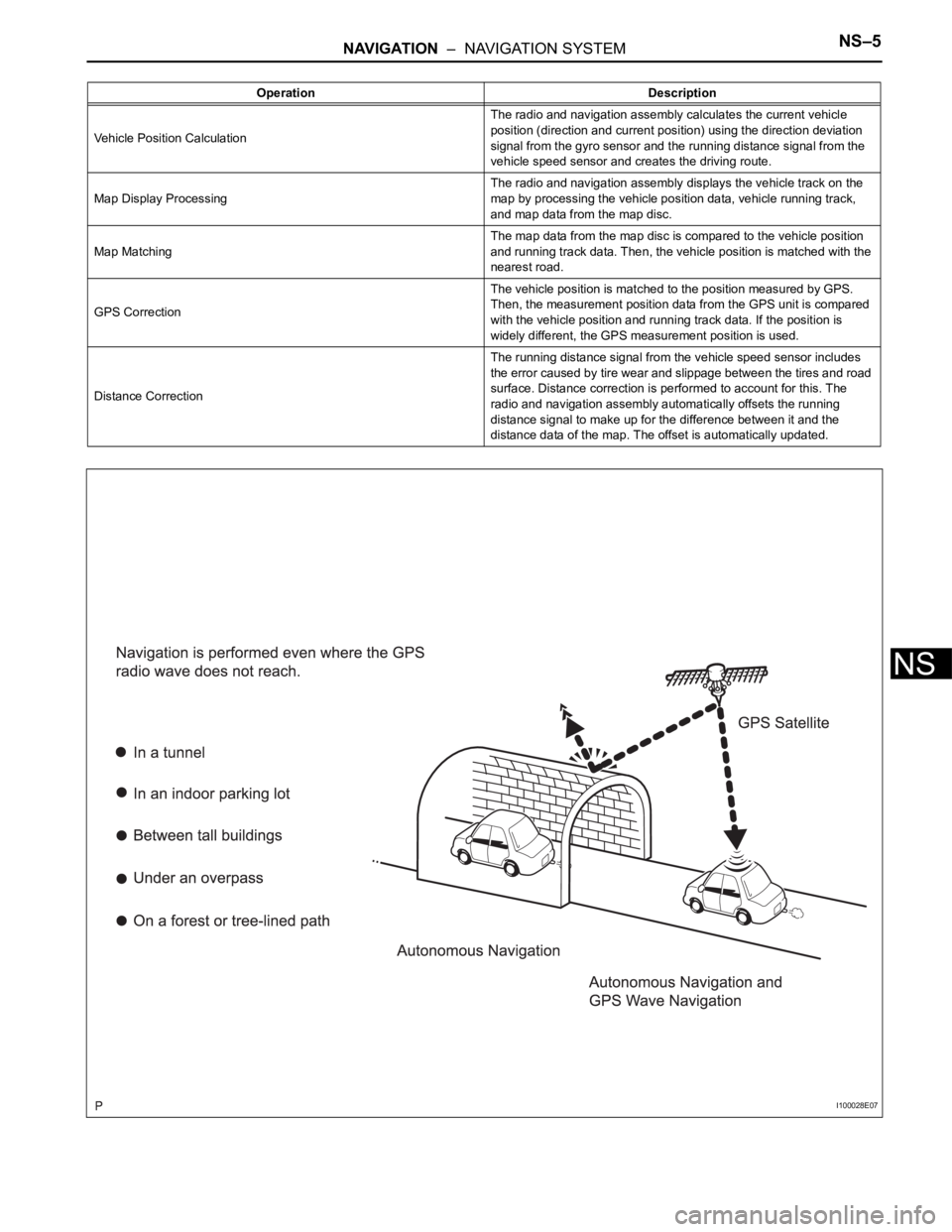
NAVIGATION – NAVIGATION SYSTEMNS–5
NS
Operation Description
Vehicle Position CalculationThe radio and navigation assembly calculates the current vehicle
position (direction and current position) using the direction deviation
signal from the gyro sensor and the running distance signal from the
vehicle speed sensor and creates the driving route.
Map Display ProcessingThe radio and navigation assembly displays the vehicle track on the
map by processing the vehicle position data, vehicle running track,
and map data from the map disc.
Map MatchingThe map data from the map disc is compared to the vehicle position
and running track data. Then, the vehicle position is matched with the
nearest road.
GPS CorrectionThe vehicle position is matched to the position measured by GPS.
Then, the measurement position data from the GPS unit is compared
with the vehicle position and running track data. If the position is
widely different, the GPS measurement position is used.
Distance CorrectionThe running distance signal from the vehicle speed sensor includes
the error caused by tire wear and slippage between the tires and road
surface. Distance correction is performed to account for this. The
radio and navigation assembly automatically offsets the running
distance signal to make up for the difference between it and the
distance data of the map. The offset is automatically updated.
I100028E07
Page 267 of 3000
NS–6NAVIGATION – NAVIGATION SYSTEM
NS
HINT:
The combination of autonomous and GPS
navigation makes it possible to display the vehicle
position even when the vehicle is in places where
the GPS radio wave cannot receive a signal. When
only autonomous navigation is used, however, the
mapping accuracy may slightly decline.
(b) Autonomous navigation
This method determines the relative vehicle position
based on the running track determined by the gyro
and vehicle speed sensors located in the radio and
navigation assembly.
(1) Gyro sensor
Calculates the direction by detecting angular
velocity. It is located in the radio and navigation
assembly.
(2) Vehicle speed sensor
Used to calculate the vehicle running distance.
Page 268 of 3000
NAVIGATION – NAVIGATION SYSTEMNS–7
NS
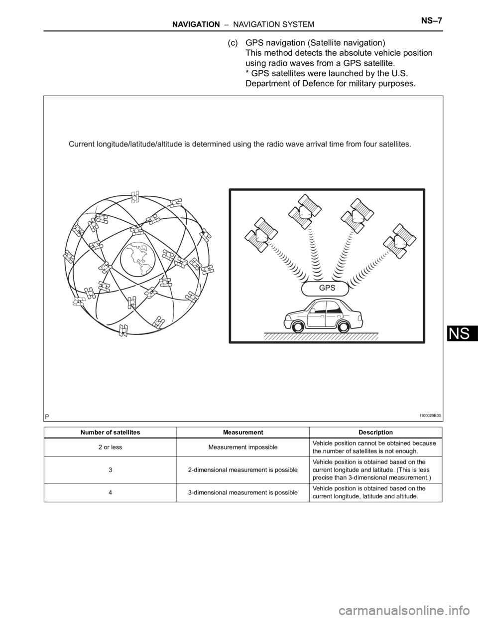
(c) GPS navigation (Satellite navigation)
This method detects the absolute vehicle position
using radio waves from a GPS satellite.
* GPS satellites were launched by the U.S.
Department of Defence for military purposes.
Number of satellites Measurement Description
2 or less Measurement impossibleVehicle position cannot be obtained because
the number of satellites is not enough.
3 2-dimensional measurement is possibleVehicle position is obtained based on the
current longitude and latitude. (This is less
precise than 3-dimensional measurement.)
4 3-dimensional measurement is possibleVehicle position is obtained based on the
current longitude, latitude and altitude.
I100029E03
Page 269 of 3000
NS–8NAVIGATION – NAVIGATION SYSTEM
NS
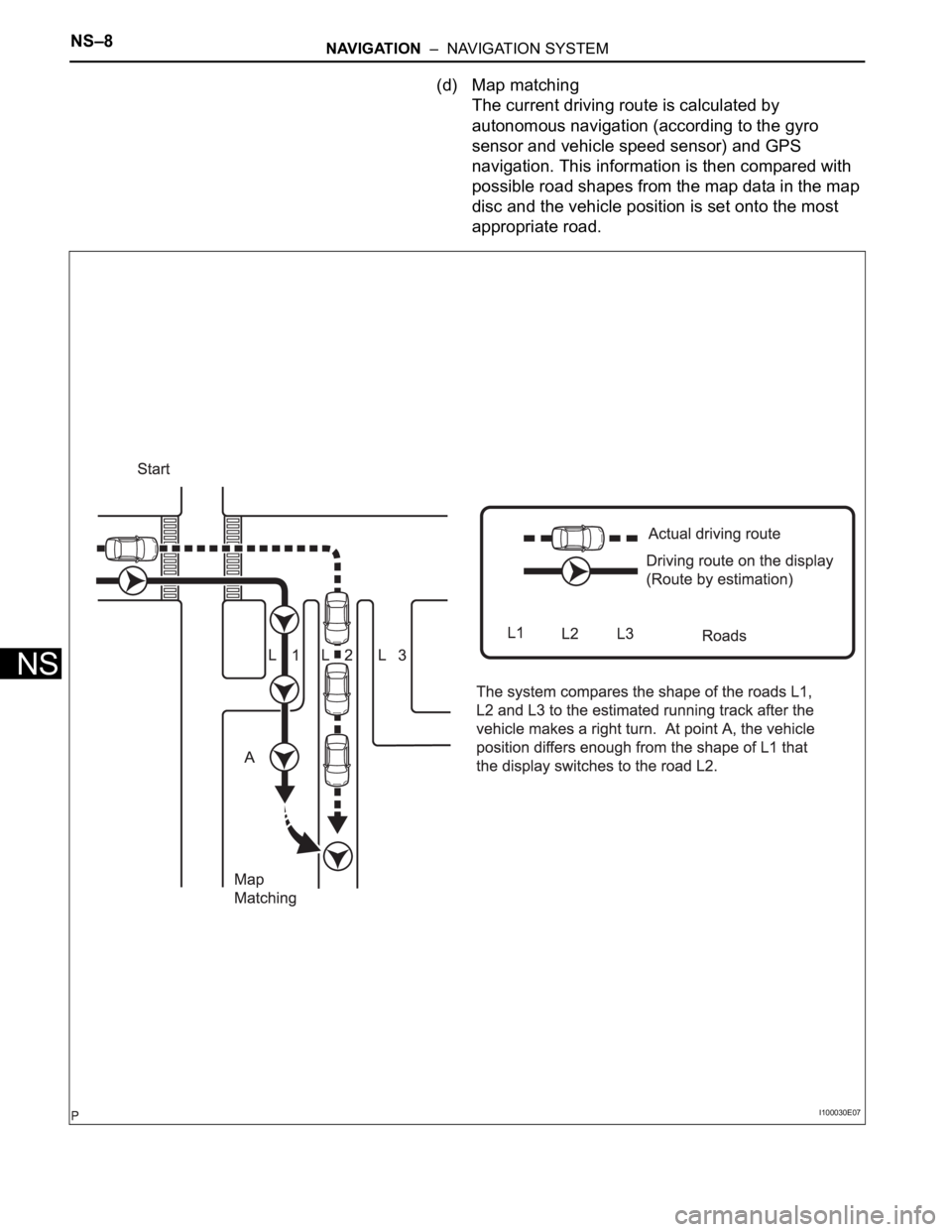
(d) Map matching
The current driving route is calculated by
autonomous navigation (according to the gyro
sensor and vehicle speed sensor) and GPS
navigation. This information is then compared with
possible road shapes from the map data in the map
disc and the vehicle position is set onto the most
appropriate road.
I100030E07
Page 270 of 3000
NAVIGATION – NAVIGATION SYSTEMNS–9
NS
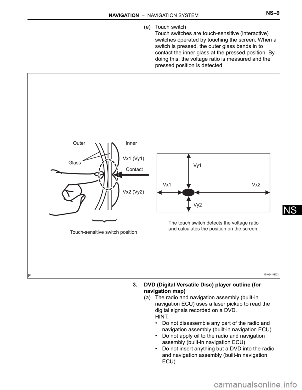
(e) Touch switch
Touch switches are touch-sensitive (interactive)
switches operated by touching the screen. When a
switch is pressed, the outer glass bends in to
contact the inner glass at the pressed position. By
doing this, the voltage ratio is measured and the
pressed position is detected.
3. DVD (Digital Versatile Disc) player outline (for
navigation map)
(a) The radio and navigation assembly (built-in
navigation ECU) uses a laser pickup to read the
digital signals recorded on a DVD.
HINT:
• Do not disassemble any part of the radio and
navigation assembly (built-in navigation ECU).
• Do not apply oil to the radio and navigation
assembly (built-in navigation ECU).
• Do not insert anything but a DVD into the radio
and navigation assembly (built-in navigation
ECU).
E106414E03
Trending: shift solenoid, automatic transmission, engine coolant, fuse box, check transmission fluid, Drive belt, knock sensor ecu
