TOYOTA SIENNA 2007 Service Repair Manual
Manufacturer: TOYOTA, Model Year: 2007, Model line: SIENNA, Model: TOYOTA SIENNA 2007Pages: 3000, PDF Size: 52.26 MB
Page 191 of 3000
POWER STEERING – VANE PUMPPS–9
PS
REMOVAL
1. DRAIN POWER STEERING FLUID
2. REMOVE FRONT WHEEL RH
3. REMOVE FRONT FENDER APRON SEAL RH (See
page EM-26)
4. REMOVE FAN AND GENERATOR V BELT (See page
EM-6)
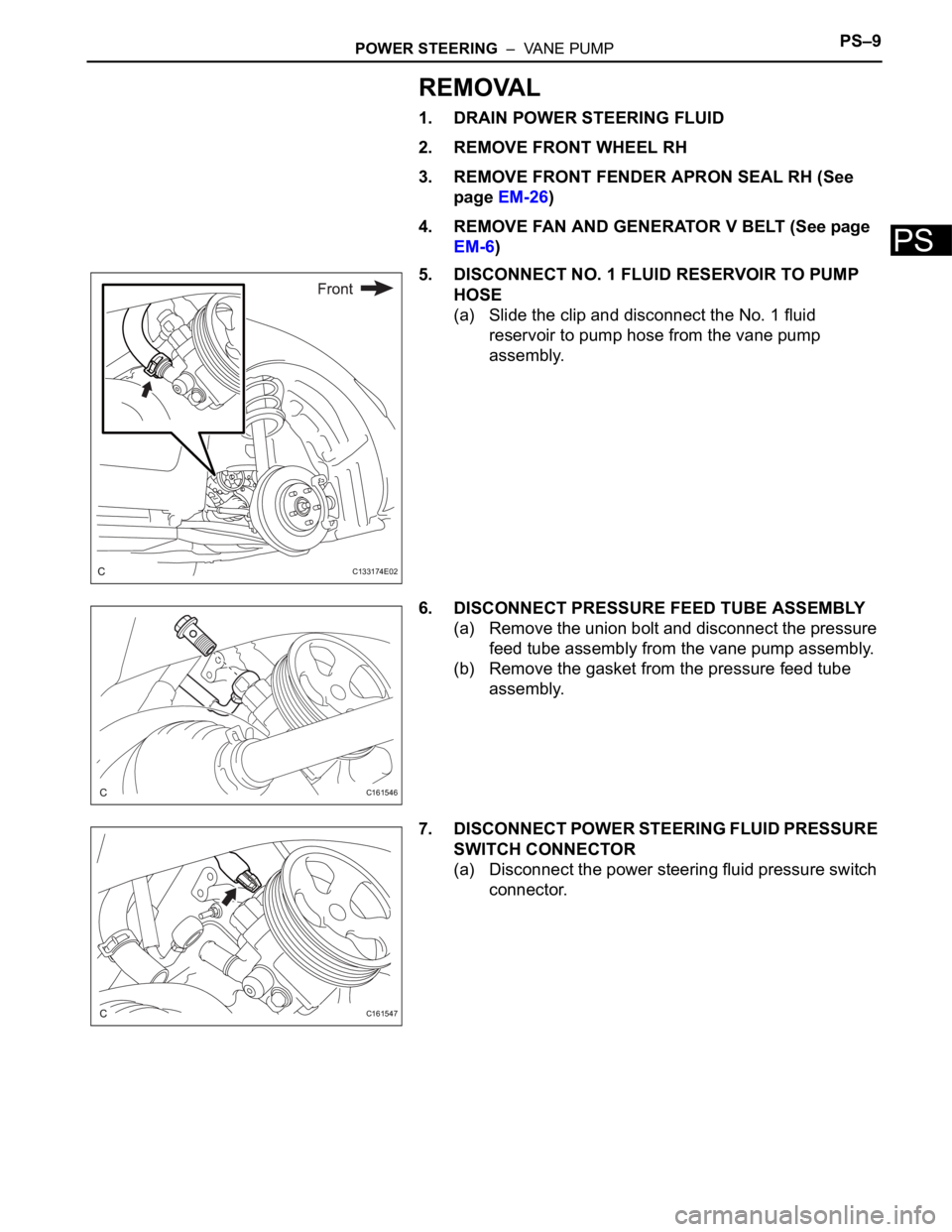
5. DISCONNECT NO. 1 FLUID RESERVOIR TO PUMP
HOSE
(a) Slide the clip and disconnect the No. 1 fluid
reservoir to pump hose from the vane pump
assembly.
6. DISCONNECT PRESSURE FEED TUBE ASSEMBLY
(a) Remove the union bolt and disconnect the pressure
feed tube assembly from the vane pump assembly.
(b) Remove the gasket from the pressure feed tube
assembly.
7. DISCONNECT POWER STEERING FLUID PRESSURE
SWITCH CONNECTOR
(a) Disconnect the power steering fluid pressure switch
connector.
C133174E02
C161546
C161547
Page 192 of 3000
PS–10POWER STEERING – VANE PUMP
PS
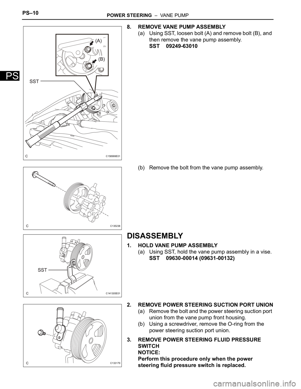
8. REMOVE VANE PUMP ASSEMBLY
(a) Using SST, loosen bolt (A) and remove bolt (B), and
then remove the vane pump assembly.
SST 09249-63010
(b) Remove the bolt from the vane pump assembly.
DISASSEMBLY
1. HOLD VANE PUMP ASSEMBLY
(a) Using SST, hold the vane pump assembly in a vise.
SST 09630-00014 (09631-00132)
2. REMOVE POWER STEERING SUCTION PORT UNION
(a) Remove the bolt and the power steering suction port
union from the vane pump front housing.
(b) Using a screwdriver, remove the O-ring from the
power steering suction port union.
3. REMOVE POWER STEERING FLUID PRESSURE
SWITCH
NOTICE:
Perform this procedure only when the power
steering fluid pressure switch is replaced.
C158999E01
C135238
C141305E01
C133179
Page 193 of 3000
POWER STEERING – VANE PUMPPS–11
PS
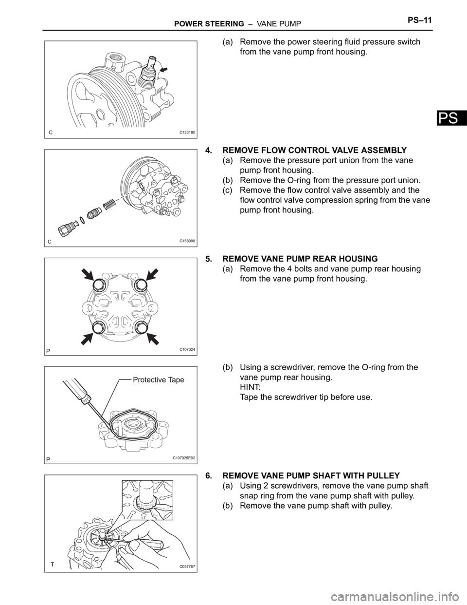
(a) Remove the power steering fluid pressure switch
from the vane pump front housing.
4. REMOVE FLOW CONTROL VALVE ASSEMBLY
(a) Remove the pressure port union from the vane
pump front housing.
(b) Remove the O-ring from the pressure port union.
(c) Remove the flow control valve assembly and the
flow control valve compression spring from the vane
pump front housing.
5. REMOVE VANE PUMP REAR HOUSING
(a) Remove the 4 bolts and vane pump rear housing
from the vane pump front housing.
(b) Using a screwdriver, remove the O-ring from the
vane pump rear housing.
HINT:
Tape the screwdriver tip before use.
6. REMOVE VANE PUMP SHAFT WITH PULLEY
(a) Using 2 screwdrivers, remove the vane pump shaft
snap ring from the vane pump shaft with pulley.
(b) Remove the vane pump shaft with pulley.
C133180
C158998
C107024
C107025E02
C057767
Page 194 of 3000
PS–12POWER STEERING – VANE PUMP
PS
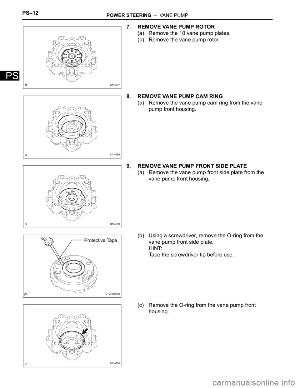
7. REMOVE VANE PUMP ROTOR
(a) Remove the 10 vane pump plates.
(b) Remove the vane pump rotor.
8. REMOVE VANE PUMP CAM RING
(a) Remove the vane pump cam ring from the vane
pump front housing.
9. REMOVE VANE PUMP FRONT SIDE PLATE
(a) Remove the vane pump front side plate from the
vane pump front housing.
(b) Using a screwdriver, remove the O-ring from the
vane pump front side plate.
HINT:
Tape the screwdriver tip before use.
(c) Remove the O-ring from the vane pump front
housing.
C114697
C114698
C114699
C107029E02
C114700
Page 195 of 3000
POWER STEERING – VANE PUMPPS–13
PS
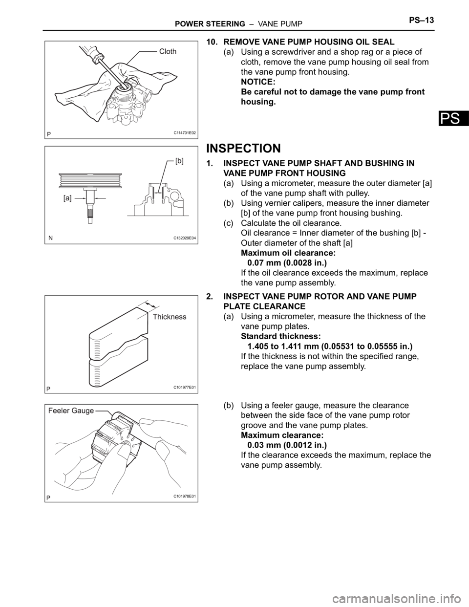
10. REMOVE VANE PUMP HOUSING OIL SEAL
(a) Using a screwdriver and a shop rag or a piece of
cloth, remove the vane pump housing oil seal from
the vane pump front housing.
NOTICE:
Be careful not to damage the vane pump front
housing.
INSPECTION
1. INSPECT VANE PUMP SHAFT AND BUSHING IN
VANE PUMP FRONT HOUSING
(a) Using a micrometer, measure the outer diameter [a]
of the vane pump shaft with pulley.
(b) Using vernier calipers, measure the inner diameter
[b] of the vane pump front housing bushing.
(c) Calculate the oil clearance.
Oil clearance = Inner diameter of the bushing [b] -
Outer diameter of the shaft [a]
Maximum oil clearance:
0.07 mm (0.0028 in.)
If the oil clearance exceeds the maximum, replace
the vane pump assembly.
2. INSPECT VANE PUMP ROTOR AND VANE PUMP
PLATE CLEARANCE
(a) Using a micrometer, measure the thickness of the
vane pump plates.
Standard thickness:
1.405 to 1.411 mm (0.05531 to 0.05555 in.)
If the thickness is not within the specified range,
replace the vane pump assembly.
(b) Using a feeler gauge, measure the clearance
between the side face of the vane pump rotor
groove and the vane pump plates.
Maximum clearance:
0.03 mm (0.0012 in.)
If the clearance exceeds the maximum, replace the
vane pump assembly.
C114701E02
C132029E04
C101977E01
C101978E01
Page 196 of 3000
PS–14POWER STEERING – VANE PUMP
PS
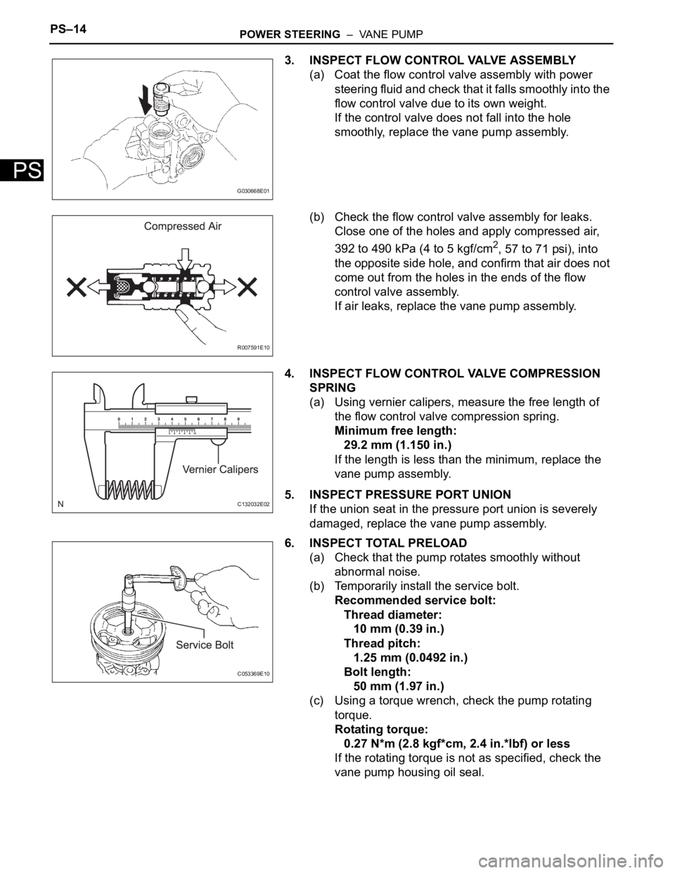
3. INSPECT FLOW CONTROL VALVE ASSEMBLY
(a) Coat the flow control valve assembly with power
steering fluid and check that it falls smoothly into the
flow control valve due to its own weight.
If the control valve does not fall into the hole
smoothly, replace the vane pump assembly.
(b) Check the flow control valve assembly for leaks.
Close one of the holes and apply compressed air,
392 to 490 kPa (4 to 5 kgf/cm
2, 57 to 71 psi), into
the opposite side hole, and confirm that air does not
come out from the holes in the ends of the flow
control valve assembly.
If air leaks, replace the vane pump assembly.
4. INSPECT FLOW CONTROL VALVE COMPRESSION
SPRING
(a) Using vernier calipers, measure the free length of
the flow control valve compression spring.
Minimum free length:
29.2 mm (1.150 in.)
If the length is less than the minimum, replace the
vane pump assembly.
5. INSPECT PRESSURE PORT UNION
If the union seat in the pressure port union is severely
damaged, replace the vane pump assembly.
6. INSPECT TOTAL PRELOAD
(a) Check that the pump rotates smoothly without
abnormal noise.
(b) Temporarily install the service bolt.
Recommended service bolt:
Thread diameter:
10 mm (0.39 in.)
Thread pitch:
1.25 mm (0.0492 in.)
Bolt length:
50 mm (1.97 in.)
(c) Using a torque wrench, check the pump rotating
torque.
Rotating torque:
0.27 N*m (2.8 kgf*cm, 2.4 in.*lbf) or less
If the rotating torque is not as specified, check the
vane pump housing oil seal.
G030668E01
R007591E10
C132032E02
C053369E10
Page 197 of 3000
SS–10SERVICE SPECIFICATIONS – 2GR-FE ENGINE MECHANICAL
SS
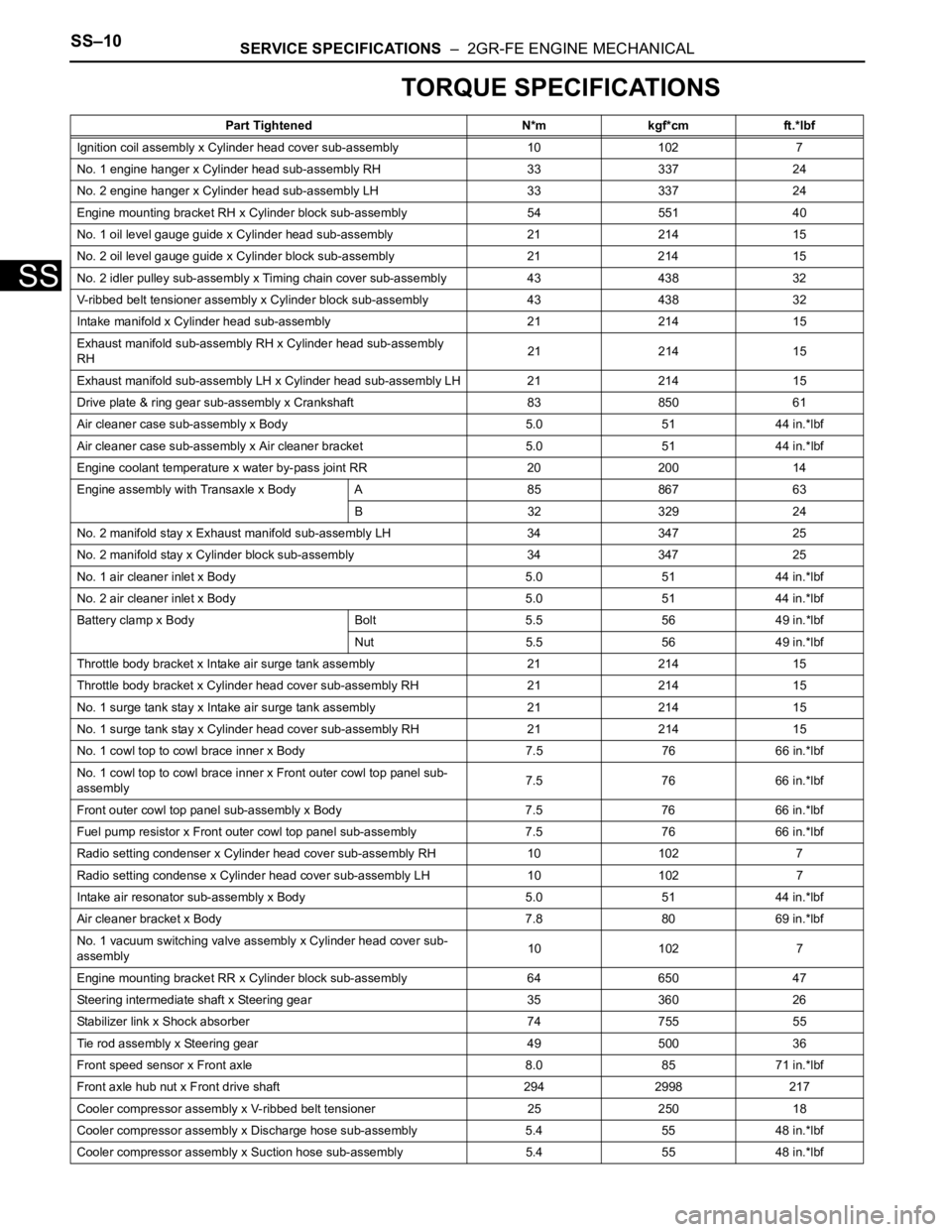
TORQUE SPECIFICATIONS
Part Tightened N*m kgf*cm ft.*lbf
Ignition coil assembly x Cylinder head cover sub-assembly 10 102 7
No. 1 engine hanger x Cylinder head sub-assembly RH 33 337 24
No. 2 engine hanger x Cylinder head sub-assembly LH 33 337 24
Engine mounting bracket RH x Cylinder block sub-assembly 54 551 40
No. 1 oil level gauge guide x Cylinder head sub-assembly 21 214 15
No. 2 oil level gauge guide x Cylinder block sub-assembly 21 214 15
No. 2 idler pulley sub-assembly x Timing chain cover sub-assembly 43 438 32
V-ribbed belt tensioner assembly x Cylinder block sub-assembly 43 438 32
Intake manifold x Cylinder head sub-assembly 21 214 15
Exhaust manifold sub-assembly RH x Cylinder head sub-assembly
RH21 214 15
Exhaust manifold sub-assembly LH x Cylinder head sub-assembly LH 21 214 15
Drive plate & ring gear sub-assembly x Crankshaft 83 850 61
Air cleaner case sub-assembly x Body 5.0 51 44 in.*lbf
Air cleaner case sub-assembly x Air cleaner bracket 5.0 51 44 in.*lbf
Engine coolant temperature x water by-pass joint RR 20 200 14
Engine assembly with Transaxle x Body A 85 867 63
B 32 329 24
No. 2 manifold stay x Exhaust manifold sub-assembly LH 34 347 25
No. 2 manifold stay x Cylinder block sub-assembly 34 347 25
No. 1 air cleaner inlet x Body 5.0 51 44 in.*lbf
No. 2 air cleaner inlet x Body 5.0 51 44 in.*lbf
Battery clamp x Body Bolt 5.5 56 49 in.*lbf
Nut 5.5 56 49 in.*lbf
Throttle body bracket x Intake air surge tank assembly 21 214 15
Throttle body bracket x Cylinder head cover sub-assembly RH 21 21415
No. 1 surge tank stay x Intake air surge tank assembly 21 214 15
No. 1 surge tank stay x Cylinder head cover sub-assembly RH 21 21415
No. 1 cowl top to cowl brace inner x Body 7.5 76 66 in.*lbf
No. 1 cowl top to cowl brace inner x Front outer cowl top panel sub-
assembly7.5 76 66 in.*lbf
Front outer cowl top panel sub-assembly x Body 7.5 76 66 in.*lbf
Fuel pump resistor x Front outer cowl top panel sub-assembly 7.576 66 in.*lbf
Radio setting condenser x Cylinder head cover sub-assembly RH 10102 7
Radio setting condense x Cylinder head cover sub-assembly LH 10 102 7
Intake air resonator sub-assembly x Body 5.0 51 44 in.*lbf
Air cleaner bracket x Body 7.8 80 69 in.*lbf
No. 1 vacuum switching valve assembly x Cylinder head cover sub-
assembly10 102 7
Engine mounting bracket RR x Cylinder block sub-assembly 64 650 47
Steering intermediate shaft x Steering gear 35 360 26
Stabilizer link x Shock absorber 74 755 55
Tie rod assembly x Steering gear 49 500 36
Front speed sensor x Front axle 8.0 85 71 in.*lbf
Front axle hub nut x Front drive shaft 294 2998 217
Cooler compressor assembly x V-ribbed belt tensioner 25 250 18
Cooler compressor assembly x Discharge hose sub-assembly 5.4 55 48 in.*lbf
Cooler compressor assembly x Suction hose sub-assembly 5.4 55 48 in.*lbf
Page 198 of 3000
SERVICE SPECIFICATIONS – 2GR-FE ENGINE MECHANICALSS–11
SS
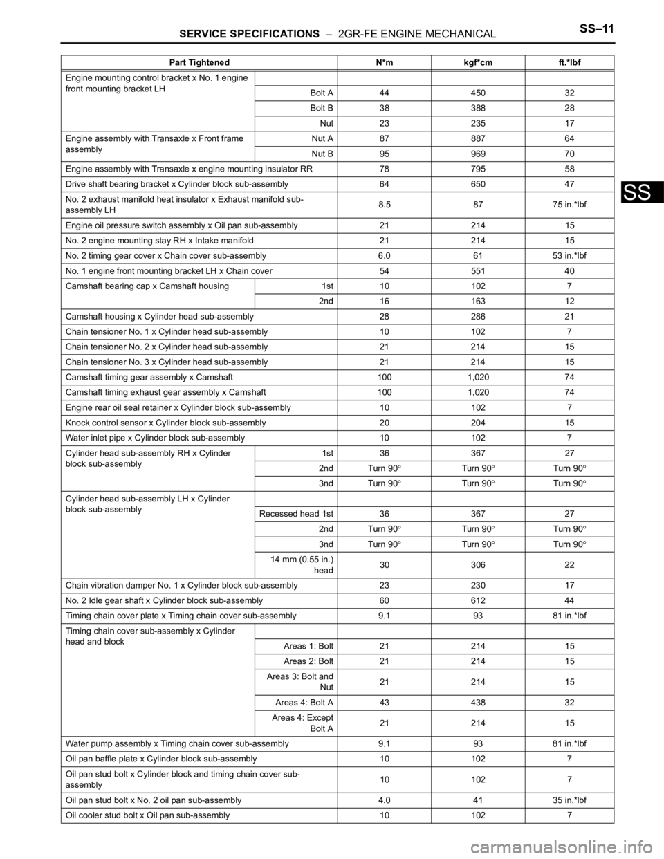
Engine mounting control bracket x No. 1 engine
front mounting bracket LH
Bolt A 44 450 32
Bolt B 38 388 28
Nut 23 235 17
Engine assembly with Transaxle x Front frame
assemblyNut A 87 887 64
Nut B 95 969 70
Engine assembly with Transaxle x engine mounting insulator RR 78795 58
Drive shaft bearing bracket x Cylinder block sub-assembly 64 650 47
No. 2 exhaust manifold heat insulator x Exhaust manifold sub-
assembly LH8.5 87 75 in.*lbf
Engine oil pressure switch assembly x Oil pan sub-assembly 21 21415
No. 2 engine mounting stay RH x Intake manifold 21 214 15
No. 2 timing gear cover x Chain cover sub-assembly 6.0 61 53 in.*lbf
No. 1 engine front mounting bracket LH x Chain cover 54 551 40
Camshaft bearing cap x Camshaft housing 1st 10 102 7
2nd 16 163 12
Camshaft housing x Cylinder head sub-assembly 28 286 21
Chain tensioner No. 1 x Cylinder head sub-assembly 10 102 7
Chain tensioner No. 2 x Cylinder head sub-assembly 21 214 15
Chain tensioner No. 3 x Cylinder head sub-assembly 21 214 15
Camshaft timing gear assembly x Camshaft 100 1,020 74
Camshaft timing exhaust gear assembly x Camshaft 100 1,020 74
Engine rear oil seal retainer x Cylinder block sub-assembly 10 1027
Knock control sensor x Cylinder block sub-assembly 20 204 15
Water inlet pipe x Cylinder block sub-assembly 10 102 7
Cylinder head sub-assembly RH x Cylinder
block sub-assembly1st 36 367 27
2nd Turn 90
Turn 90Turn 90
3nd Turn 90Turn 90Turn 90
Cylinder head sub-assembly LH x Cylinder
block sub-assembly
Recessed head 1st 36 367 27
2nd Turn 90
Turn 90Turn 90
3nd Turn 90Turn 90Turn 90
14 mm (0.55 in.)
head30 306 22
Chain vibration damper No. 1 x Cylinder block sub-assembly 23 23017
No. 2 Idle gear shaft x Cylinder block sub-assembly 60 612 44
Timing chain cover plate x Timing chain cover sub-assembly 9.1 9381 in.*lbf
Timing chain cover sub-assembly x Cylinder
head and block
Areas 1: Bolt 21 214 15
Areas 2: Bolt 21 214 15
Areas 3: Bolt and
Nut21 214 15
Areas 4: Bolt A 43 438 32
Areas 4: Except
Bolt A21 214 15
Water pump assembly x Timing chain cover sub-assembly 9.1 93 81 in.*lbf
Oil pan baffle plate x Cylinder block sub-assembly 10 102 7
Oil pan stud bolt x Cylinder block and timing chain cover sub-
assembly10 102 7
Oil pan stud bolt x No. 2 oil pan sub-assembly 4.0 41 35 in.*lbf
Oil cooler stud bolt x Oil pan sub-assembly 10 102 7Part Tightened N*m kgf*cm ft.*lbf
Page 199 of 3000
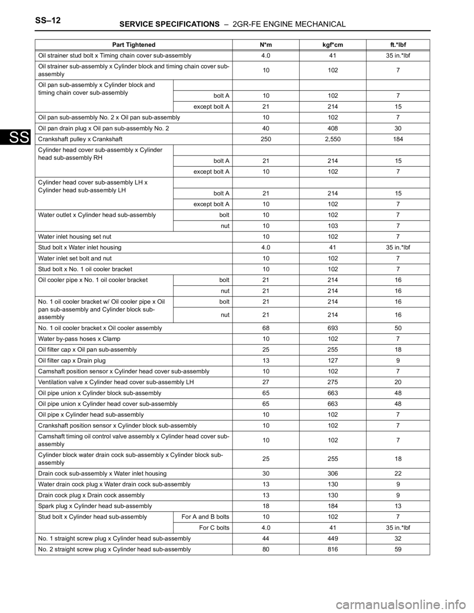
SS–12SERVICE SPECIFICATIONS – 2GR-FE ENGINE MECHANICAL
SS
Oil strainer stud bolt x Timing chain cover sub-assembly 4.0 41 35 in.*lbf
Oil strainer sub-assembly x Cylinder block and timing chain cover sub-
assembly10 102 7
Oil pan sub-assembly x Cylinder block and
timing chain cover sub-assembly
bolt A 10 102 7
except bolt A 21 214 15
Oil pan sub-assembly No. 2 x Oil pan sub-assembly 10 102 7
Oil pan drain plug x Oil pan sub-assembly No. 2 40 408 30
Crankshaft pulley x Crankshaft 250 2,550 184
Cylinder head cover sub-assembly x Cylinder
head sub-assembly RH
bolt A 21 214 15
except bolt A 10 102 7
Cylinder head cover sub-assembly LH x
Cylinder head sub-assembly LH
bolt A 21 214 15
except bolt A 10 102 7
Water outlet x Cylinder head sub-assembly bolt 10 102 7
nut 10 103 7
Water inlet housing set nut 10 102 7
Stud bolt x Water inlet housing 4.0 41 35 in.*lbf
Water inlet set bolt and nut 10 102 7
Stud bolt x No. 1 oil cooler bracket 10 102 7
Oil cooler pipe x No. 1 oil cooler bracket bolt 21 214 16
nut 21 214 16
No. 1 oil cooler bracket w/ Oil cooler pipe x Oil
pan sub-assembly and Cylinder block sub-
assemblybolt 21 214 16
nut 21 214 16
No. 1 oil cooler bracket x Oil cooler assembly 68 693 50
Water by-pass hoses x Clamp 10 102 7
Oil filter cap x Oil pan sub-assembly 25 255 18
Oil filter cap x Drain plug 13 127 9
Camshaft position sensor x Cylinder head cover sub-assembly 10 1027
Ventilation valve x Cylinder head cover sub-assembly LH 27 275 20
Oil pipe union x Cylinder block sub-assembly 65 663 48
Oil pipe union x Cylinder head cover sub-assembly 65 663 48
Oil pipe x Cylinder head sub-assembly 10 102 7
Crankshaft position sensor x Cylinder block sub-assembly 10 102 7
Camshaft timing oil control valve assembly x Cylinder head cover sub-
assembly10 102 7
Cylinder block water drain cock sub-assembly x Cylinder block sub-
assembly25 255 18
Drain cock sub-assembly x Water inlet housing 30 306 22
Water drain cock plug x Water drain cock sub-assembly 13 130 9
Drain cock plug x Drain cock assembly 13 130 9
Spark plug x Cylinder head sub-assembly 18 184 13
Stud bolt x Cylinder head sub-assembly For A and B bolts 10 102 7
For C bolts 4.0 41 35 in.*lbf
No. 1 straight screw plug x Cylinder head sub-assembly 44 449 32
No. 2 straight screw plug x Cylinder head sub-assembly 80 816 59Part Tightened N*m kgf*cm ft.*lbf
Page 200 of 3000
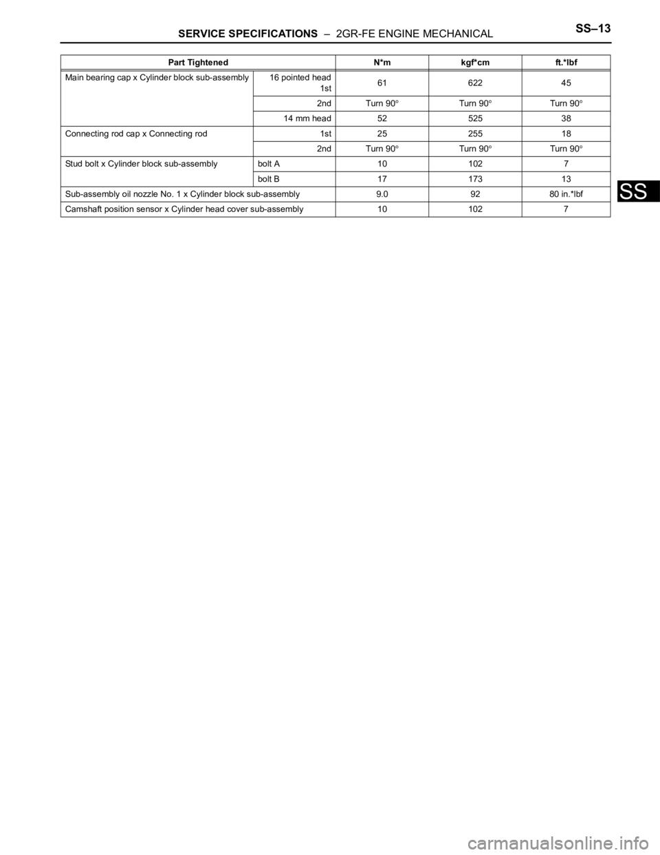
SERVICE SPECIFICATIONS – 2GR-FE ENGINE MECHANICALSS–13
SS
Main bearing cap x Cylinder block sub-assembly 16 pointed head
1st61 622 45
2nd Turn 90
Turn 90Turn 90
14 mm head 52 525 38
Connecting rod cap x Connecting rod 1st 25 255 18
2nd Turn 90
Turn 90Turn 90
Stud bolt x Cylinder block sub-assembly bolt A 10 102 7
bolt B 17 173 13
Sub-assembly oil nozzle No. 1 x Cylinder block sub-assembly 9.0 92 80 in.*lbf
Camshaft position sensor x Cylinder head cover sub-assembly 10 1027 Part Tightened N*m kgf*cm ft.*lbf