TOYOTA SUPRA 2022 Owners Manual
Manufacturer: TOYOTA, Model Year: 2022, Model line: SUPRA, Model: TOYOTA SUPRA 2022Pages: 498, PDF Size: 104.06 MB
Page 151 of 498
149
3
3-1. CONTROLS
CONTROLS
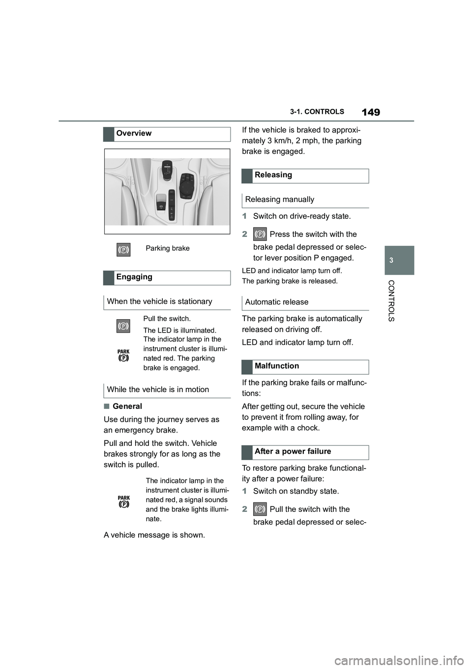
■General
Use during the journey serves as
an emergency brake.
Pull and hold the switch. Vehicle
brakes strongly for as long as the
switch is pulled.
A vehicle message is shown.
If the vehicle is braked to approxi-
mately 3 km/h, 2 mph, the parking
brake is engaged.
1 Switch on drive-ready state.
2 Press the switch with the
brake pedal depressed or selec-
tor lever position P engaged.
LED and indicator lamp turn off.
The parking brake is released.
The parking brake is automatically
released on driving off.
LED and indicator lamp turn off.
If the parking brake fails or malfunc-
tions:
After getting out, secure the vehicle
to prevent it from rolling away, for
example with a chock.
To restore parking brake functional-
ity after a power failure:
1 Switch on standby state.
2 Pull the switch with the
brake pedal depressed or selec-
Overview
Parking brake
Engaging
When the vehicle is stationary
Pull the switch.
The LED is illuminated.
The indicator lamp in the
instrument cluster is illumi-
nated red. The parking
brake is engaged.
While the vehicle is in motion
The indicator lamp in the
instrument cluster is illumi-
nated red, a signal sounds
and the brake lights illumi-
nate.
Releasing
Releasing manually
Automatic release
Malfunction
After a power failure
Page 152 of 498
1503-1. CONTROLS
tor lever position P engaged and
then press it.
The procedure can take a few sec-
onds. Any sounds that occur are
normal.
Do not fold in the exterior mirrors
while driving or while operating the
turn indicators or hazard warning
lights to ensure that the turn indica-
tors in the exterior mirrors are well
recognisable.
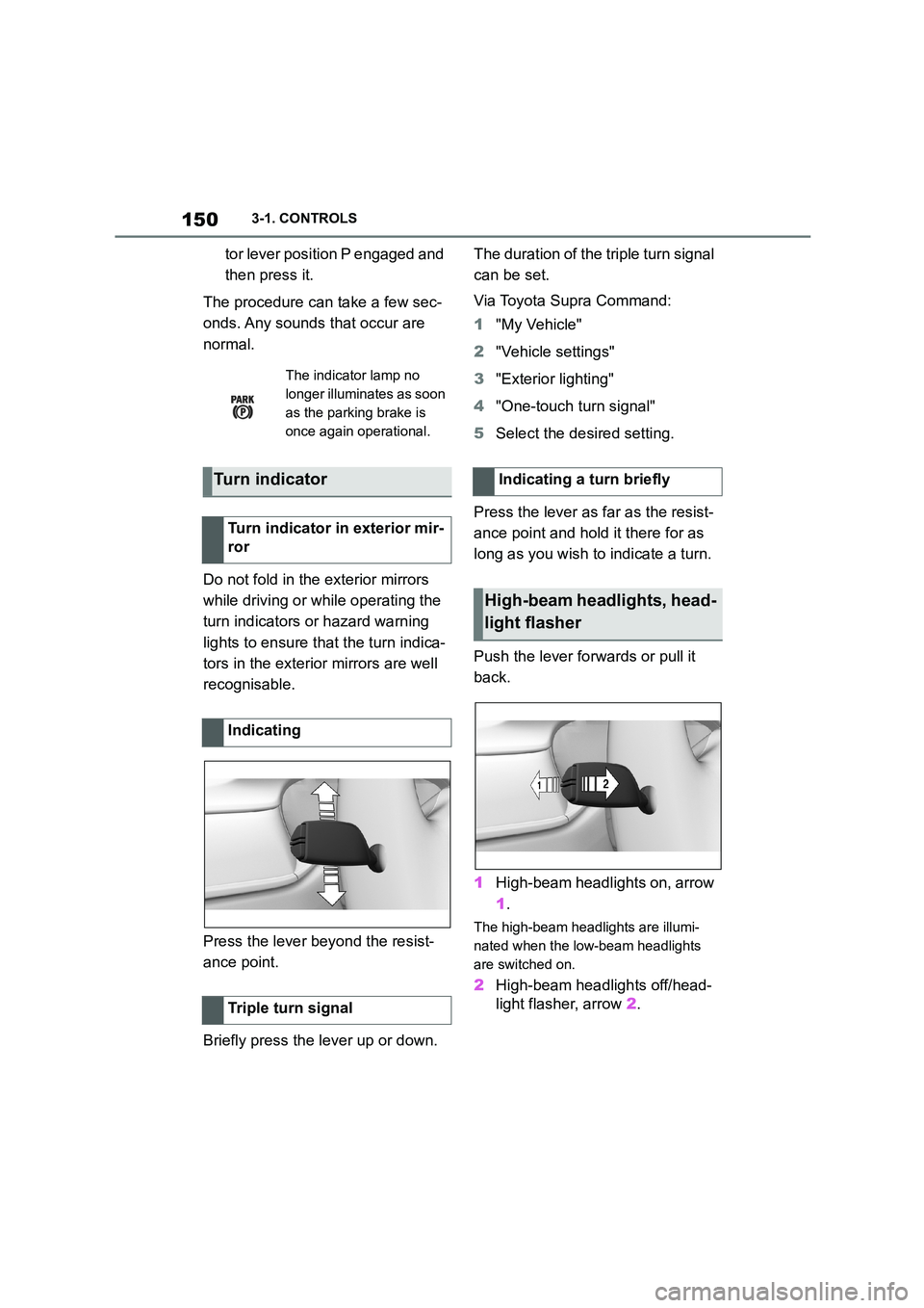
Press the lever beyond the resist-
ance point.
Briefly press the lever up or down.
The duration of the triple turn signal
can be set.
Via Toyota Supra Command:
1 "My Vehicle"
2 "Vehicle settings"
3 "Exterior lighting"
4 "One-touch turn signal"
5 Select the desired setting.
Press the lever as far as the resist-
ance point and hold it there for as
long as you wish to indicate a turn.
Push the lever forwards or pull it
back.
1 High-beam headlights on, arrow
1 .
The high-beam headlights are illumi-
nated when the low-beam headlights
are switched on.
2 High-beam headlights off/head-
light flasher, arrow 2.
The indicator lamp no
longer illuminates as soon
as the parking brake is
once again operational.
Turn indicator
Turn indicator in exterior mir-
ror
Indicating
Triple turn signal
Indicating a turn briefly
High-beam headlights, head-
light flasher
Page 153 of 498
151
3
3-1. CONTROLS
CONTROLS
Do not use the wipers on a dry
windscreen, otherwise the wiper
blades will wear or become dam-
aged more quickly.
The wipers can be operated in the
standby state.
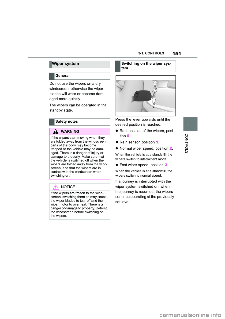
Press the lever upwards until the
desired position is reached.
Rest position of the wipers, posi-
tion 0.
Rain sensor, position 1.
Normal wiper speed, position 2.
When the vehicle is at a standstill, the
wipers switch to intermittent mode.
Fast wiper speed, position 3.
When the vehicle is at a standstill, the
wipers switch to normal speed.
If a journey is in terrupted with the
wiper system switched on: when
the journey is resumed, the wipers
continue operating at the previously
set level.
Wiper system
General
Safety notes
WA R N I N G
If the wipers start moving when they
are folded away from the windscreen,
parts of the body may become trapped or the vehicle may be dam-
aged. There is a danger of injury or
damage to property. Make sure that the vehicle is switched off when the
wipers are folded away from the wind-
screen, and that the wipers are in contact with the windscreen when
switching on.
NOTICE
If the wipers are frozen to the wind- screen, switching them on may cause
the wiper blades to tear off and the
wiper motor to overheat. There is a danger of damage to property. Defrost
the windscreen before switching on
the wipers.
Switching on the wiper sys-
tem
Page 154 of 498
1523-1. CONTROLS
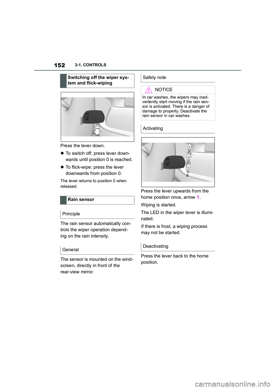
Press the lever down.
To switch off: press lever down-
wards until position 0 is reached.
To flick-wipe: press the lever
downwards from position 0.
The lever returns to position 0 when
released.
The rain sensor automatically con-
trols the wiper operation depend-
ing on the rain intensity.
The sensor is mounted on the wind-
screen, directly in front of the
rear-view mirror.
Press the lever upwards from the
home position once, arrow 1.
Wiping is started.
The LED in the wiper lever is illumi-
nated.
If there is frost, a wiping process
may not be started.
Press the lever back to the home
position.
Switching off the wiper sys-
tem and flick-wiping
Rain sensor
Principle
General
Safety note
NOTICE
In car washes, the wipers may inad-
vertently start moving if the rain sen- sor is activated. There is a danger of
damage to property. Deactivate the
rain sensor in car washes.
Activating
Deactivating
Page 155 of 498
153
3
3-1. CONTROLS
CONTROLS
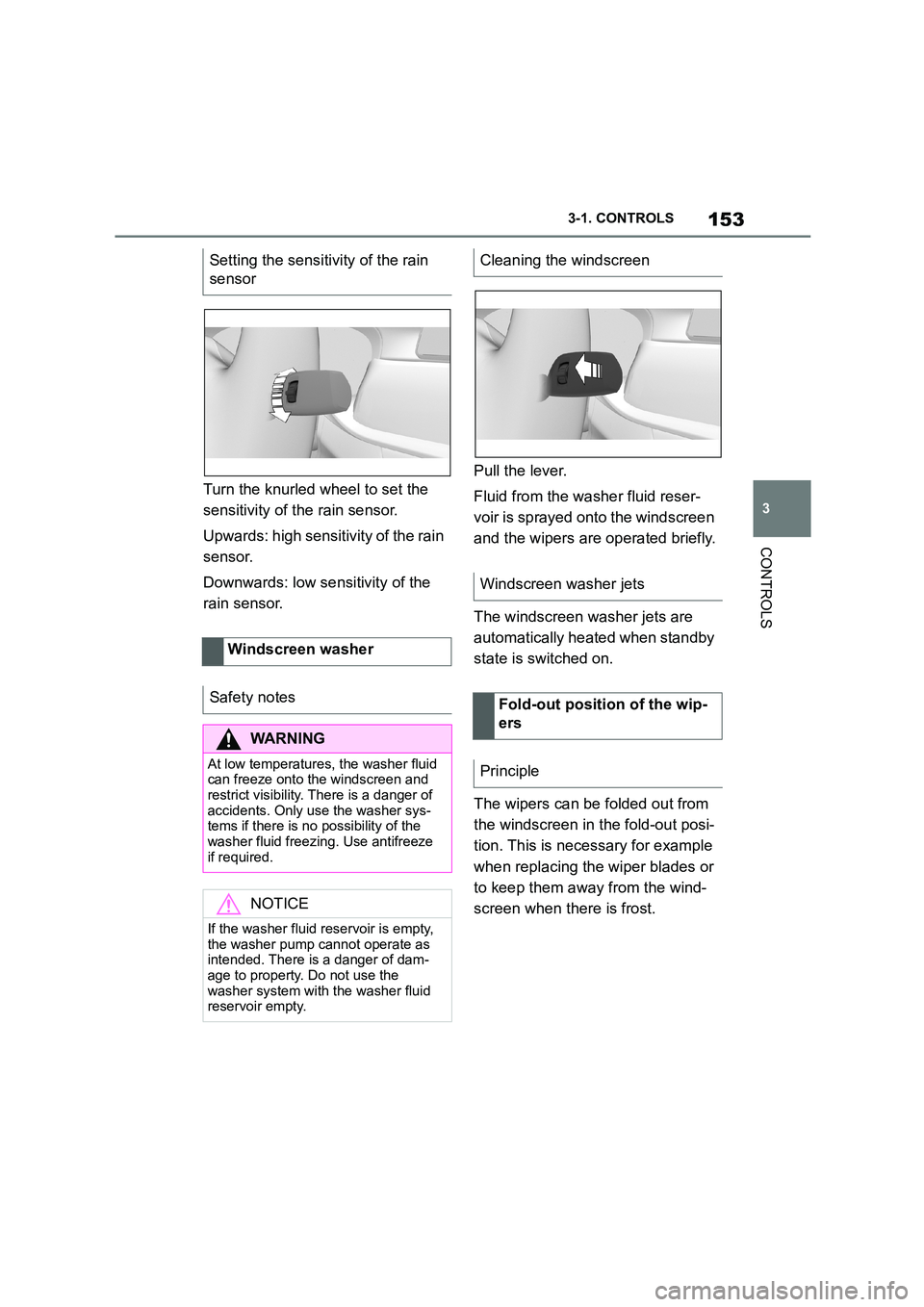
Turn the knurled wheel to set the
sensitivity of t he rain sensor.
Upwards: high sensitivity of the rain
sensor.
Downwards: low se nsitivity of the
rain sensor.
Pull the lever.
Fluid from the washer fluid reser-
voir is sprayed on to the windscreen
and the wipers are operated briefly.
The windscreen washer jets are
automatically heated when standby
state is switched on.
The wipers can be folded out from
the windscreen in the fold-out posi-
tion. This is necessary for example
when replacing the wiper blades or
to keep them away from the wind-
screen when there is frost.
Setting the sensitivity of the rain
sensor
Windscreen washer
Safety notes
WA R N I N G
At low temperatures, the washer fluid can freeze onto the windscreen and
restrict visibility. There is a danger of
accidents. Only use the washer sys- tems if there is no possibility of the
washer fluid freezing. Use antifreeze
if required.
NOTICE
If the washer fluid reservoir is empty,
the washer pump cannot operate as
intended. There is a danger of dam- age to property. Do not use the
washer system with the washer fluid
reservoir empty.
Cleaning the windscreen
Windscreen washer jets
Fold-out position of the wip-
ers
Principle
Page 156 of 498
1543-1. CONTROLS
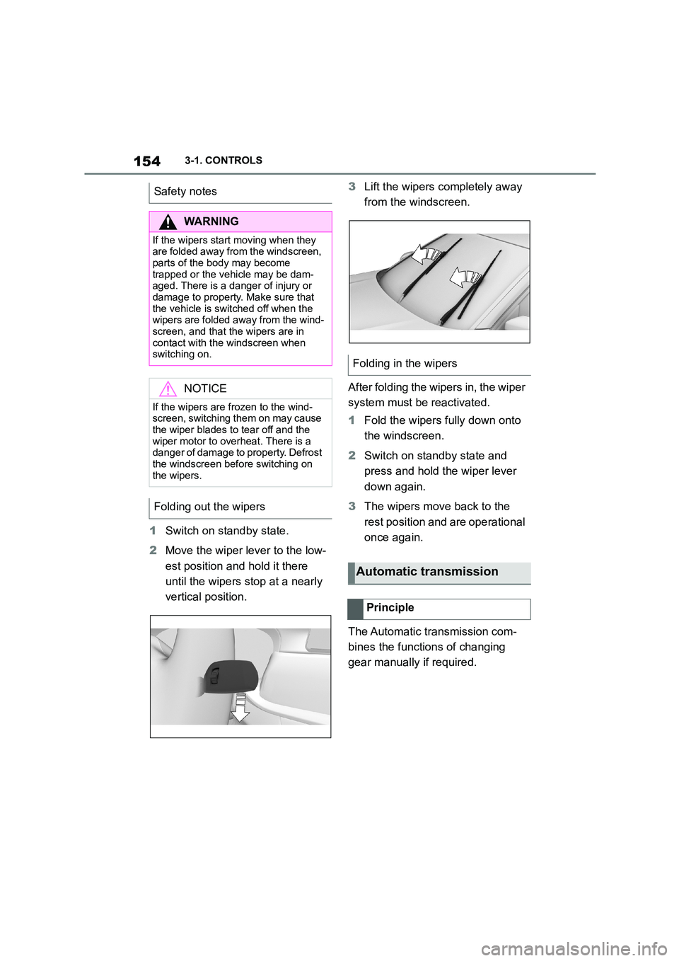
1Switch on standby state.
2 Move the wiper lever to the low-
est position and hold it there
until the wipers stop at a nearly
vertical position.
3 Lift the wipers completely away
from the windscreen.
After folding the wipers in, the wiper
system must be reactivated.
1 Fold the wipers fully down onto
the windscreen.
2 Switch on standby state and
press and hold the wiper lever
down again.
3 The wipers move back to the
rest position and are operational
once again.
The Automatic transmission com-
bines the functions of changing
gear manually if required.
Safety notes
WA R N I N G
If the wipers start moving when they
are folded away from the windscreen, parts of the body may become
trapped or the vehicle may be dam-
aged. There is a danger of injury or damage to property. Make sure that
the vehicle is switched off when the
wipers are folded away from the wind-
screen, and that the wipers are in contact with the windscreen when
switching on.
NOTICE
If the wipers are frozen to the wind-
screen, switching them on may cause
the wiper blades to tear off and the wiper motor to overheat. There is a
danger of damage to property. Defrost
the windscreen before switching on the wipers.
Folding out the wipers
Folding in the wipers
Automatic transmission
Principle
Page 157 of 498
155
3
3-1. CONTROLS
CONTROLS
Selector lever posi tion for all nor-
mal driving. All gears for forward
driving are selected automatically.
Only engage selector lever posi-
tion R when the vehicle is station-
ary.
In selector lever position N, the
vehicle can be pushed or can roll
without power from the engine, for
example in car washes, see page
156.
Selector lever position for parking
the vehicle, for example. In selector
lever position P, the transmission
blocks the drive wheels.
Only engage selector lever posi-
tion P when the vehicle is station-
ary.
■P is engaged automatically
Selector lever position P is auto-
matically engaged in the following
situations, for example:
After switching off drive-ready
state if selector lever position R,
D or M is engaged.
After switching off standby state
if selector leve r position N is
engaged.
If, while the vehicle is at a stand-
still and selector le ver position D,
M or R is engaged, the driver's
seat belt is unfastened, the
driver's door is opened and the
brake pedal is not depressed.
Apply the brakes until you are
ready to drive off, otherwise the
vehicle will move wh en a drive posi-
tion is selected.
Safety note
WA R N I N G
An unsecured vehicle can start mov-
ing and rolling away. There is a dan- ger of accidents. Before leaving the
vehicle, secure it to prevent it from
rolling away, for example by applying the parking brake.
Observe the following to ensure that
the vehicle is secured against rolling away:
• Apply the parking brake.
• Turn the front wheels towards the
kerb on upward or downward gradi- ents.
• Additionally secure the vehicle on upward or downward gradients, for
example with a chock.
Selector lever positions
D drive position
R Reverse
N neutral
P Park
Engaging selector lever posi-
tions
General
Page 158 of 498
1563-1. CONTROLS
The selector lever will only move
from position P to another selector
lever position if drive-ready state is
switched on and the brake pedal is
depressed.
It may not be possible to move out
of selector lever position P until all
technical require ments are fulfilled.
A selector lever lock prevents the
following incorrect operation:
Inadvertent shifting to selector
lever position R.
Inadvertent change from selector
lever position P to another selec-
tor lever position.
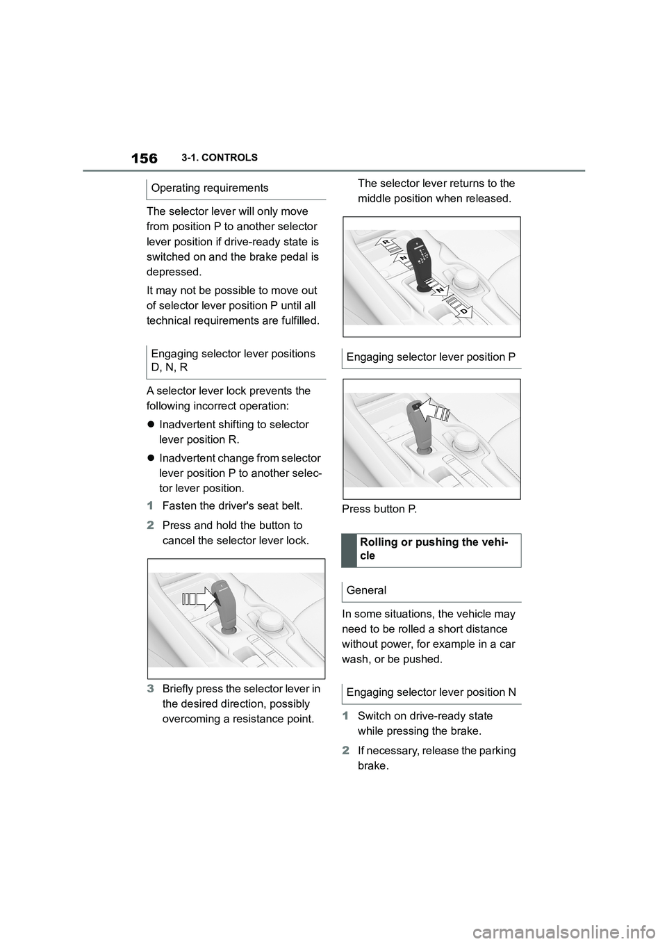
1 Fasten the driver's seat belt.
2 Press and hold the button to
cancel the selector lever lock.
3 Briefly press the selector lever in
the desired direction, possibly
overcoming a resistance point.
The selector leve r returns to the
middle position when released.
Press button P.
In some situations, the vehicle may
need to be rolled a short distance
without power, for example in a car
wash, or be pushed.
1 Switch on drive-ready state
while pressing the brake.
2 If necessary, release the parking
brake.
Operating requirements
Engaging selector lever positions
D, N, REngaging selector lever position P
Rolling or pushing the vehi-
cle
General
Engaging selector lever position N
Page 159 of 498
157
3
3-1. CONTROLS
CONTROLS
3 Depress the brake pedal.
4 Touch the selector lever lock
and engage selector lever posi-
tion N.
5 Switch off drive-ready state.
Standby state then remains switched
on and a vehicle message is shown.
The vehicle can now roll.
Selector lever position P is auto-
matically engaged after approxi-
mately 35 minutes.
If there is a fault, it may not be pos-
sible to change the selector lever
position.
Unlock the transmission lockout
electronically if necessary, see
page 158.
Kick-down enables you to achieve
maximum performance.
Press the accelerator pedal down
beyond the regular full-throttle posi-
tion; resistance will be felt.
The gears can be changed manu-
ally in manual operation.
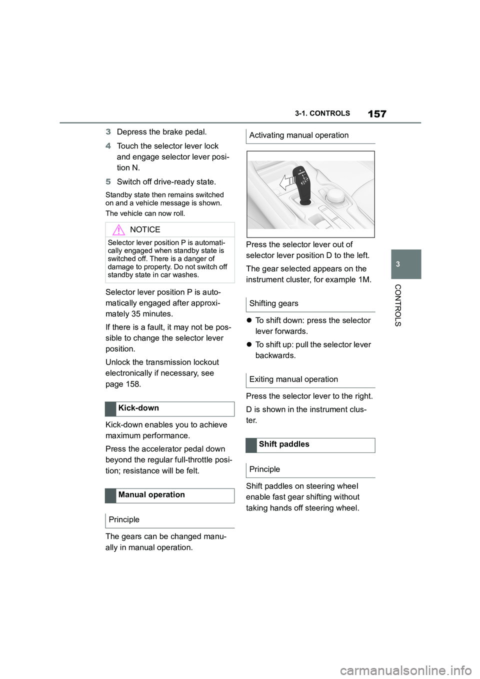
Press the selector lever out of
selector lever position D to the left.
The gear selected appears on the
instrument cluster, for example 1M.
To shift down: press the selector
lever forwards.
To shift up: pull the selector lever
backwards.
Press the selector lever to the right.
D is shown in the instrument clus-
ter.
Shift paddles on steering wheel
enable fast gear shifting without
taking hands off steering wheel.
NOTICE
Selector lever position P is automati- cally engaged when standby state is
switched off. There is a danger of
damage to property. Do not switch off standby state in car washes.
Kick-down
Manual operation
Principle
Activating manual operation
Shifting gears
Exiting manual operation
Shift paddles
Principle
Page 160 of 498
1583-1. CONTROLS
■Gearshift
Gear shifting is only carried out at
the appropriate engine RPM and
vehicle speed.
■Short-term manual operation
In selector lever position D, operat-
ing a shift paddle causes the sys-
tem to switch to manual operation
temporarily.
The gearbox reverts to automatic
operation from manual operation
after a certain period of time of
moderate driving without accelera-
tion or gear shifts using the shift
paddles.
Changing to automatic operation is
possible as follows:
Pull and hold the right shift pad-
dle until D is shown in the instru-
ment cluster.
In addition to pulling the right
shift paddle, pull the left shift
paddle.
■Permanent manual operation
In selector lever position M, operat-
ing a shift paddle causes the sys-
tem to switch permanently to
manual operation (mode).
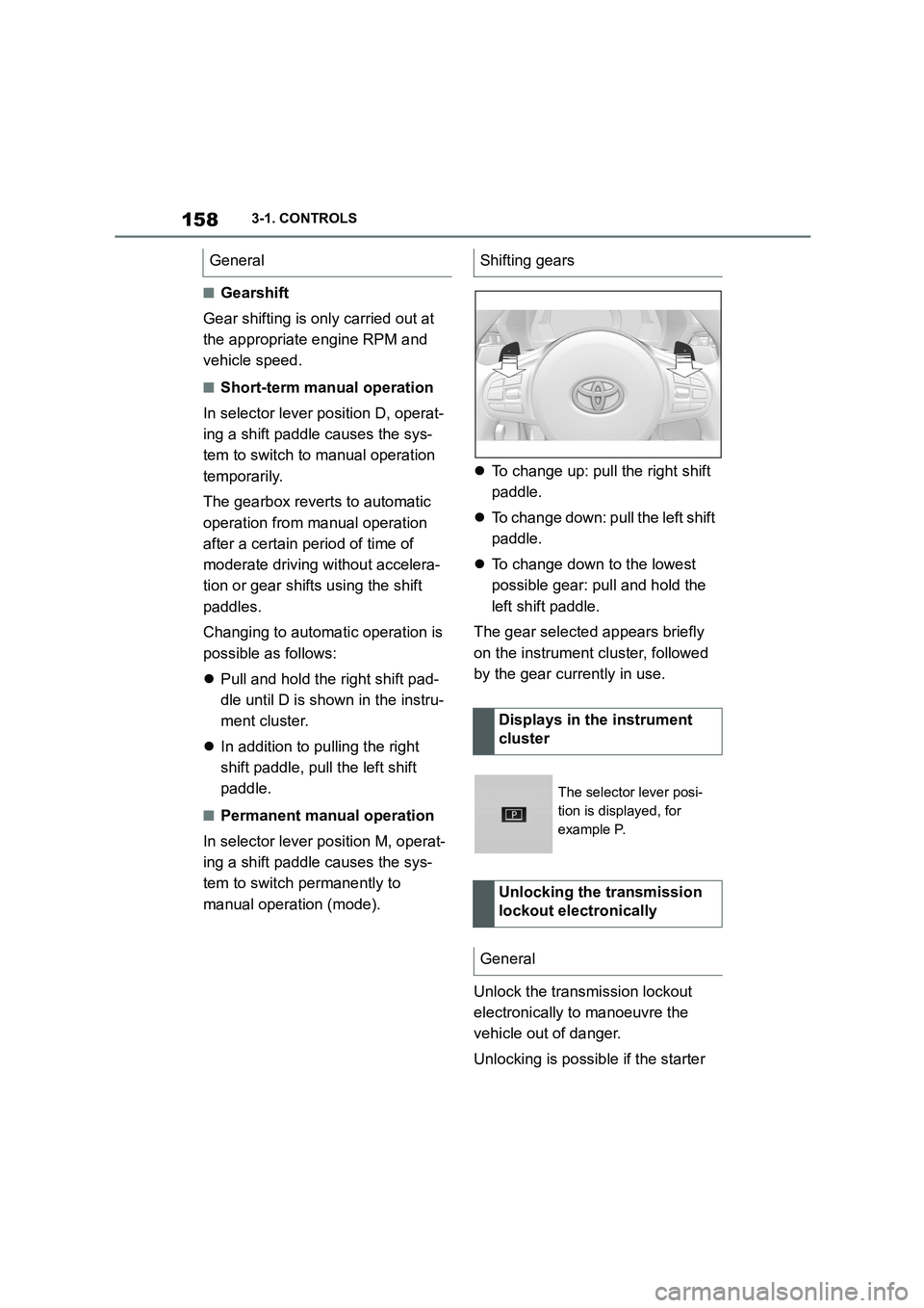
To change up: pull the right shift
paddle.
To change down: pull the left shift
paddle.
To change down to the lowest
possible gear: pull and hold the
left shift paddle.
The gear selected appears briefly
on the instrument cluster, followed
by the gear currently in use.
Unlock the transmission lockout
electronically to manoeuvre the
vehicle out of danger.
Unlocking is possible if the starter
GeneralShifting gears
Displays in the instrument
cluster
The selector lever posi-
tion is displayed, for
example P.
Unlocking the transmission
lockout electronically
General