TOYOTA SUPRA 2022 Owners Manual
Manufacturer: TOYOTA, Model Year: 2022, Model line: SUPRA, Model: TOYOTA SUPRA 2022Pages: 498, PDF Size: 104.06 MB
Page 141 of 498
139
3
3-1. CONTROLS
CONTROLS
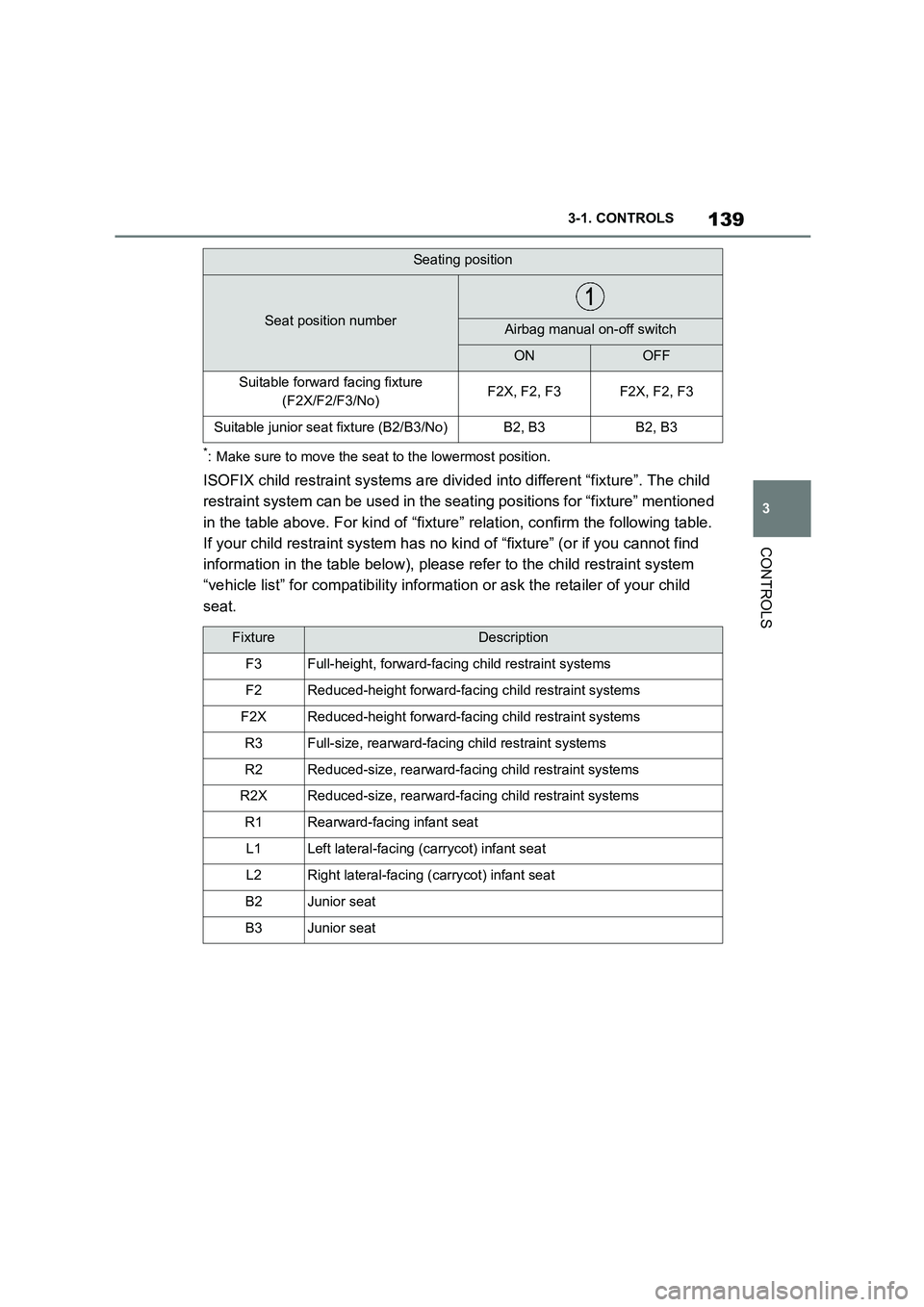
*: Make sure to move the seat to the lowermost position.
ISOFIX child restraint systems are divid ed into different “fixture”. The child
restraint system can be used in the se ating positions for “fixture” mentioned
in the table above. For kind of “fixtu re” relation, confirm the following table.
If your child restraint system has no ki nd of “fixture” (or if you cannot find
information in the table below), please refer to the child restraint system
“vehicle list” for compatib ility information or ask the retailer of your child
seat.
Suitable forward facing fixture
(F2X/F2/F3/No)F2X, F2, F3F2X, F2, F3
Suitable junior seat fixture (B2/B3/No)B2, B3B2, B3
FixtureDescription
F3Full-height, forward-faci ng child restraint systems
F2Reduced-height forward-facing child restraint systems
F2XReduced-height forward-facing child restraint systems
R3Full-size, rearward-facing child restraint systems
R2Reduced-size, rearward-facing child restraint systems
R2XReduced-size, rearward-facing child restraint systems
R1Rearward-facing infant seat
L1Left lateral-facing (carrycot) infant seat
L2Right lateral-facing (carrycot) infant seat
B2Junior seat
B3Junior seat
Seating position
Seat position numberAirbag manual on-off switch
ONOFF
Page 142 of 498
1403-1. CONTROLS
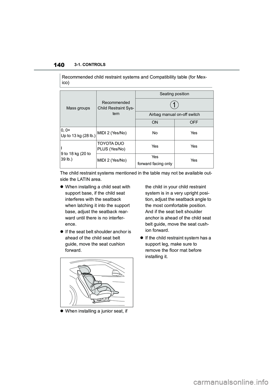
The child restraint systems mentioned in the table may not be available out-
side the LATIN area.
When installing a child seat with
support base, if the child seat
interferes with the seatback
when latching it into the support
base, adjust the seatback rear-
ward until there is no interfer-
ence.
If the seat belt shoulder anchor is
ahead of the child seat belt
guide, move the seat cushion
forward.
When installing a junior seat, if
the child in your child restraint
system is in a very upright posi-
tion, adjust the seatback angle to
the most comfortable position.
And if the seat belt shoulder
anchor is ahead of the child seat
belt guide, move the seat cush-
ion forward.
If the child restraint system has a
support leg, make sure to
remove the floor mat before
installing it.
Recommended child restra int systems and Compatibility table (for Mex-
ico)
Mass groups
Recommended
Child Restraint Sys-
tem
Seating position
Airbag manual on-off switch
ONOFF
0, 0+
Up to 13 kg (28 lb.)MIDI 2 (Yes/No)NoYe s
I
9 to 18 kg (20 to
39 lb.)
TOYOTA DUO
PLUS (Yes/No)Ye sYe s
MIDI 2 (Yes/No)Ye s
forward facing onlyYe s
Page 143 of 498
141
3
3-1. CONTROLS
CONTROLS
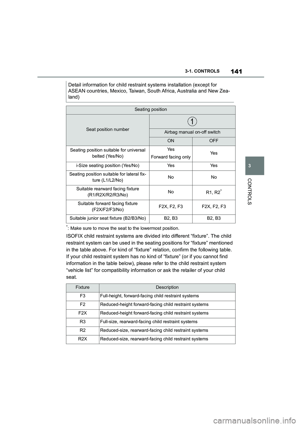
*: Make sure to move the seat to the lowermost position.
ISOFIX child restraint systems are divid ed into different “fixture”. The child
restraint system can be used in the se ating positions for “fixture” mentioned
in the table above. For kind of “fixtu re” relation, confirm the following table.
If your child restraint system has no ki nd of “fixture” (or if you cannot find
information in the table below), please refer to the child restraint system
“vehicle list” for compatib ility information or ask the retailer of your child
seat.
Detail information for ch ild restraint systems installation (except for
ASEAN countries, Mexico, Taiwan, So uth Africa, Australia and New Zea-
land)
Seating position
Seat position numberAirbag manual on-off switch
ONOFF
Seating position suitable for universal
belted (Yes/No)
Ye s
Forward facing onlyYe s
i-Size seating position (Yes/No)Ye sYe s
Seating position suitable for lateral fix-
ture (L1/L2/No)NoNo
Suitable rearward facing fixture
(R1/R2X/R2/R3/No)NoR1, R2*
Suitable forward facing fixture
(F2X/F2/F3/No)F2X, F2, F3F2X, F2, F3
Suitable junior seat fixture (B2/B3/No)B2, B3B2, B3
FixtureDescription
F3Full-height, forward-faci ng child restraint systems
F2Reduced-height forward-facing child restraint systems
F2XReduced-height forward-facing child restraint systems
R3Full-size, rearward-facing child restraint systems
R2Reduced-size, rearward-facing child restraint systems
R2XReduced-size, rearward-facing child restraint systems
Page 144 of 498
1423-1. CONTROLS
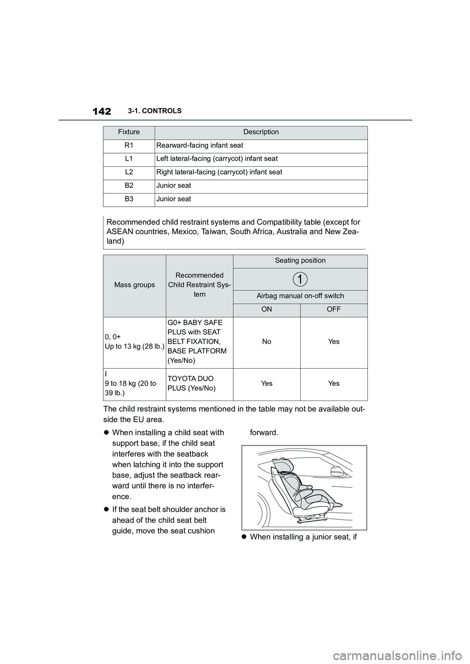
The child restraint systems mentioned in the table may not be available out-
side the EU area.
When installing a child seat with
support base, if the child seat
interferes with the seatback
when latching it into the support
base, adjust the seatback rear-
ward until there is no interfer-
ence.
If the seat belt shoulder anchor is
ahead of the child seat belt
guide, move the seat cushion
forward.
When installing a junior seat, if
R1Rearward-facing infant seat
L1Left lateral-facing (carrycot) infant seat
L2Right lateral-facing (carrycot) infant seat
B2Junior seat
B3Junior seat
Recommended child restraint systems and Compatibility table (except for
ASEAN countries, Mexico, Taiwan, So uth Africa, Australia and New Zea-
land)
Mass groups
Recommended
Child Restraint Sys-
tem
Seating position
Airbag manual on-off switch
ONOFF
0, 0+
Up to 13 kg (28 lb.)
G0+ BABY SAFE
PLUS with SEAT
BELT FIXATION,
BASE PLATFORM
(Yes/No)
NoYe s
I
9 to 18 kg (20 to
39 lb.)
TOYOTA DUO
PLUS (Yes/No)Ye sYe s
FixtureDescription
Page 145 of 498
143
3
3-1. CONTROLS
CONTROLS
the child in your child restraint
system is in a very upright posi-
tion, adjust the seatback angle to
the most comfortable position.
And if the seat belt shoulder
anchor is ahead of the child seat
belt guide, move the seat cush-
ion forward.
If the child restraint system has a
support leg, make sure to
remove the floor mat before
installing it.
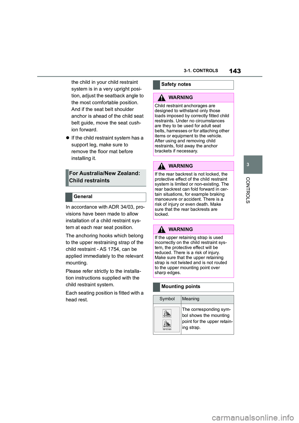
In accordance with ADR 34/03, pro-
visions have been made to allow
installation of a child restraint sys-
tem at each rear seat position.
The anchoring hooks which belong
to the upper restraining strap of the
child restraint - AS 1754, can be
applied immediately to the relevant
mounting.
Please refer strictly to the installa-
tion instructions supplied with the
child restraint system.
Each seating position is fitted with a
head rest.
For Australia/New Zealand:
Child restraints
General
Safety notes
WA R N I N G
Child restraint anchorages are
designed to withstand only those loads imposed by correctly fitted child
restraints. Under no circumstances
are they to be used for adult seat belts, harnesses or for attaching other
items or equipment to the vehicle.
After using and removing child
restraints, fold away the anchor brackets if necessary.
WA R N I N G
If the rear backrest is not locked, the protective effect of the child restraint
system is limited or non-existing. The
rear backrest can fold forward in cer- tain situations, for example braking
manoeuvre or accident. There is a
risk of injury or even death. Make sure that the rear backrests are
locked.
WA R N I N G
If the upper retaining strap is used incorrectly on the child restraint sys-
tem, the protective effect will be
reduced. There is a risk of injury. Make sure that the upper retaining
strap is not twisted and is not routed
to the upper mounting point over sharp edges.
Mounting points
SymbolMeaning
The corresponding sym-
bol shows the mounting
point for the upper retain-
ing strap.
Page 146 of 498
1443-1. CONTROLS
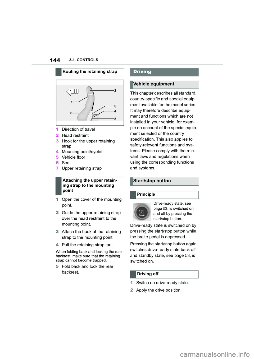
1Direction of travel
2 Head restraint
3 Hook for the upper retaining
strap
4 Mounting point/eyelet
5 Vehicle floor
6 Seat
7 Upper retaining strap
1 Open the cover of the mounting
point.
2 Guide the upper retaining strap
over the head restraint to the
mounting point.
3 Attach the hook of the retaining
strap to the mounting point.
4 Pull the retaining strap taut.
When folding back and locking the rear
backrest, make sure that the retaining
strap cannot become trapped.
5 Fold back and lock the rear
backrest.
This chapter describes all standard,
country-specific and special equip-
ment available for the model series.
It may therefore describe equip-
ment and functions which are not
installed in your vehicle, for exam-
ple on account of the special equip-
ment selected or the country
specification. This also applies to
safety-relevant functions and sys-
tems. Please comply with the rele-
vant laws and regulations when
using the corresponding functions
and systems.
Drive-ready state is switched on by
pressing the start/stop button while
the brake pedal is depressed.
Pressing the start/stop button again
switches drive-ready state back off
and standby state, see page 53, is
switched on.
1 Switch on drive-ready state.
2 Apply the drive position.
Routing the retaining strap
Attaching the upper retain-
ing strap to the mounting
point
Driving
Vehicle equipment
Start/stop button
Principle
Drive-ready state, see
page 53, is switched on
and off by pressing the
start/stop button.
Driving off
Page 147 of 498
145
3
3-1. CONTROLS
CONTROLS
3 Releasing the parking brake.
4 Drive off.
The Auto Start/Stop helps you to
save fuel. The system switches the
engine off when stationary, for
example in congestion or at traffic
lights. The drive-ready state
remains switched on. For driving
off, the engine starts automatically.
Each time the engine is started via
the start/stop button, the Auto
Start/Stop is switched to standby.
The function is activated from a
speed of around 5 km/h, approxi-
mately 3 mph.
Depending on selected drive mode,
see page 160, the system is acti-
vated or deactivated automatically.
The engine is automatically shut
down when stationary under the fol-
lowing conditions:
Selector lever in selector lever
position D.
Brake pedal remains pressed
while the vehicle is at a standstill.
Driver's seat belt buckled or
driver's door closed.
If the engine was not switched off
automatically when the vehicle
came to a stop, it can be switched
off manually:
Rapidly press the brake pedal
from the current position.
Engage selector lever position P.
If all the operating requirements
have been met, the engine is
stopped.
The air flow rate of the air condi-
tioning system is reduced when the
engine is not running.
■General
The engine is not shut down auto-
matically in the following situations:
Auto Start/Stop
Principle
General
Stopping the engine
Operating requirements
Manual engine stop
Air conditioning system when the
vehicle is parked
Displays in the instrument cluster
The display in the instru-
ment cluster indicates that
the Auto Start/Stop func-
tion is ready for automati-
cally starting the engine.
The display indicates that
the preconditions for an
automatic engine stop are
not met.
Functional limitations
Page 148 of 498
1463-1. CONTROLS
On steep downward gradients.
Brake not pressed strongly
enough.
High outside temperature and
operation of the automatic air
conditioning.
Interior not heated or cooled to
the desired temperature.
Where there is a risk of conden-
sation when the automatic air
conditioning is switched on.
Engine or other parts not at oper-
ating temperature.
Engine cooling is required.
Sharp steering angle or steering
operation.
Vehicle battery is heavily dis-
charged.
At high altitudes.
Bonnet is unlocked.
Park Assistant is activated.
Stop-and-go traffic.
Selector lever position in N or R.
After reversing.
Use of fuel with high ethanol
content.
For driving off, the engine automati-
cally starts under the following con-
ditions:
By releasing the brake pedal.
After starting the engine, accelerate
as normal.
After an automatic shut down, the
engine will not rest art automatically,
if one of the following conditions is
met:
Driver's seat belt unbuckled and
driver's door open.
Bonnet has been unlocked.
Several indicator lamps illuminate
for various lengths of time.
The engine can only be started
using the start/stop button.
Even if you do not want to drive off,
the engine restarts automatically in
the following situations:
Very high temperature in the
interior when the cooling function
is switched on.
Very low temperature in the inte-
rior when the heating is switched
on.
Where there is a risk of conden-
sation when the automatic air
conditioning is switched on.
When the steering wheel is
turned.
Shift from selector lever position
D to N or R.
Engine start
Operating requirements
Driving off
Safety function
System limits
Page 149 of 498
147
3
3-1. CONTROLS
CONTROLS
Shift from selector lever position
P to N, D or R.
Vehicle battery is heavily dis-
charged.
Start of an oil level measure-
ment.
Depending on the equipment ver-
sion and country version, the vehi-
cle has various sensors to record
the traffic situation. This enables
the intelligent auto matic Start/Stop
function to adapt to various traffic
situations and, where necessary,
behave in an anticipatory manner.
For example, in the following situa-
tions:
If a situation is detected in which
the duration of the stop is likely
to be very short, the engine is not
stopped automatically. Depend-
ing on the situation, a message
is shown on the Control Display.
If a situation is detected in which
the vehicle should drive off
immediately, the stopped engine
is started automatically.
The function may be limited if the
navigation data is invalid, outdated
or not available, for example.
The engine is not switched off auto-
matically.
During an automatic engine stop,
the engine is started.
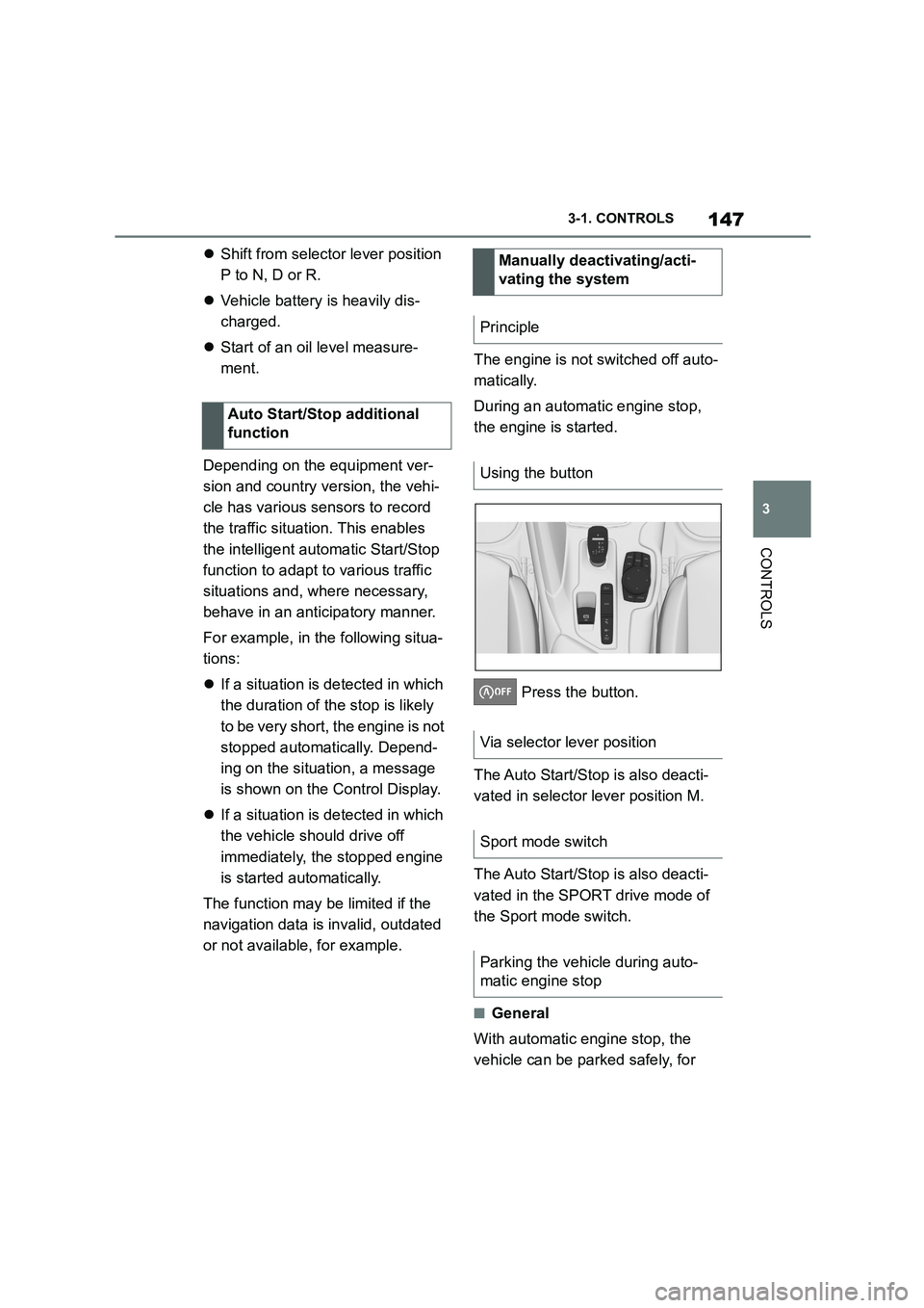
Press the button.
The Auto Start/Stop is also deacti-
vated in selector lever position M.
The Auto Start/Stop is also deacti-
vated in the SPORT drive mode of
the Sport mode switch.
■General
With automatic engine stop, the
vehicle can be parked safely, for
Auto Start/Stop additional
function
Manually deactivating/acti-
vating the system
Principle
Using the button
Via selector lever position
Sport mode switch
Parking the vehicle during auto-
matic engine stop
Page 150 of 498
1483-1. CONTROLS
example in order to leave it.
1 Press the start/stop button.
Drive-ready state is switched off.
Standby state is switched on.
Selector lever position P is auto-
matically engaged.
2 Apply the parking brake.
In certain situations the Auto
Start/Stop is deactivated automati-
cally for safety reasons, for exam-
ple if the absence of the driver is
detected.
The Auto Start/Stop no longer shuts
down the engine automatically. A
vehicle message is shown. It is
possible to keep driving. Have the
system checked by any authorized
Toyota retailer or Toyota authorized
repairer, or any reliable repairer.
The parking brake is used to pre-
vent the vehicle from rolling when it
is parked.
Automatic deactivation
General
Malfunction
Parking brake
Principle
Safety notes
WA R N I N G
An unsecured vehicle can start mov-
ing and rolling away. There is a risk of accident. Before leaving the vehicle,
secure it to prevent it from rolling
away.
Observe the following to ensure that
the vehicle is secured against rolling
away:
●Apply the parking brake.
●Turn the front wheels towards the kerb on upward or downward gradi-
ents.
●Additionally secure the vehicle on
upward or downward gradients, for
example with a chock.
WA R N I N G
Unsupervised children or pets in the
vehicle can set the vehicle in motion
and endanger themselves or other road users, for example by the follow-
ing actions:
●Pressing the start/stop button.
●Releasing the parking brake.
●Opening and closing doors or win-
dows.
●Engaging selector lever position N.
●Operating vehicle equipment.
There is a risk of accidents or injury. Do not leave children or pets unsu-
pervised in the vehicle. When leaving
the vehicle, take the remote control with you and lock the vehicle.