TOYOTA TACOMA 2009 Owners Manual (in English)
TACOMA 2009
TOYOTA
TOYOTA
https://www.carmanualsonline.info/img/14/42940/w960_42940-0.png
TOYOTA TACOMA 2009 Owners Manual (in English)
Trending: engine, climate control, maintenance reset, phone, service indicator, coolant, child lock
Page 321 of 520
321
3-6. Other interior features
3
Interior and exterior features
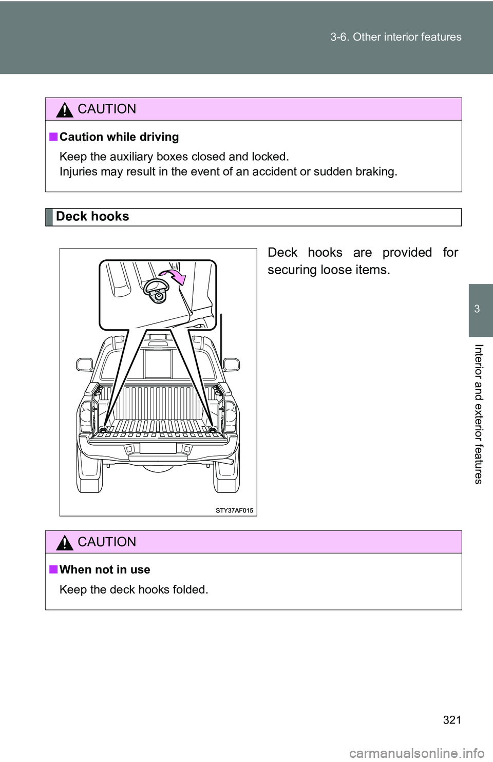
Deck hooks
Deck hooks are provided for
securing loose items.
CAUTION
■Caution while driving
Keep the auxiliary boxes closed and locked.
Injuries may result in the event of an accident or sudden braking.
CAUTION
■When not in use
Keep the deck hooks folded.
Page 322 of 520
322 3-6. Other interior features
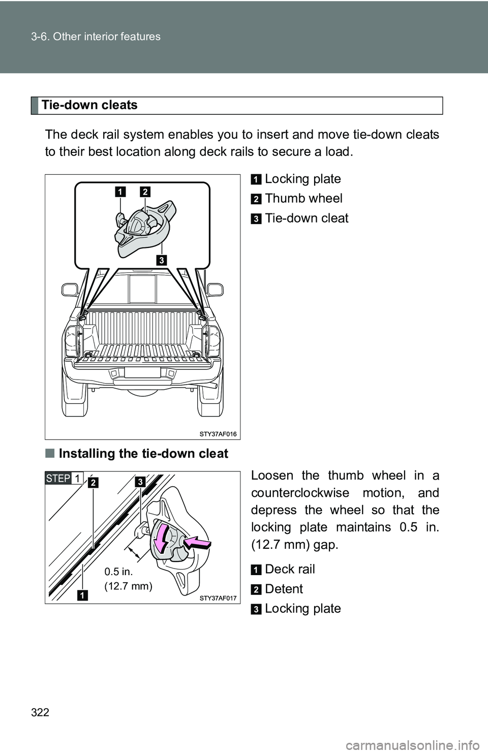
Tie-down cleatsThe deck rail system enables you to insert and move tie-down cleats
to their best location along deck rails to secure a load.
Locking plate
Thumb wheel
Tie-down cleat
■ Installing the tie-down cleat
Loosen the thumb wheel in a
counterclockwise motion, and
depress the wheel so that the
locking plate maintains 0.5 in.
(12.7 mm) gap.
Deck rail
Detent
Locking plate
0.5 in.
(12.7 mm)
Page 323 of 520
323
3-6. Other interior features
3
Interior and exterior features
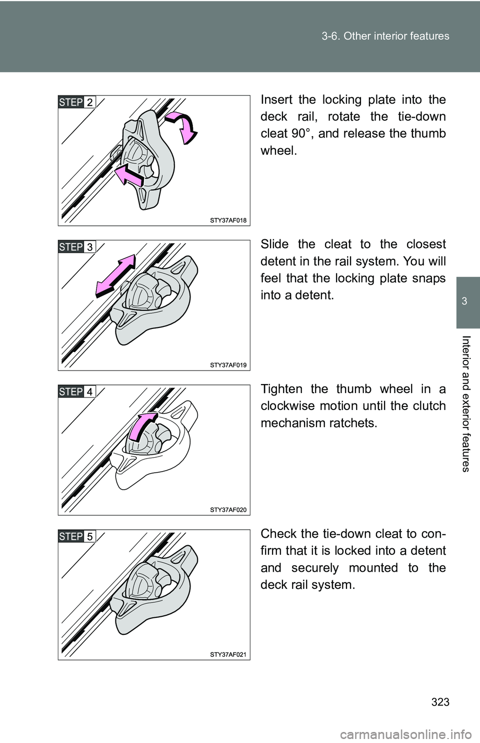
Insert the locking plate into the
deck rail, rotate the tie-down
cleat 90°, and release the thumb
wheel.
Slide the cleat to the closest
detent in the rail system. You will
feel that the locking plate snaps
into a detent.
Tighten the thumb wheel in a
clockwise motion until the clutch
mechanism ratchets.
Check the tie-down cleat to con-
firm that it is locked into a detent
and securely mounted to the
deck rail system.
Page 324 of 520
324 3-6. Other interior features
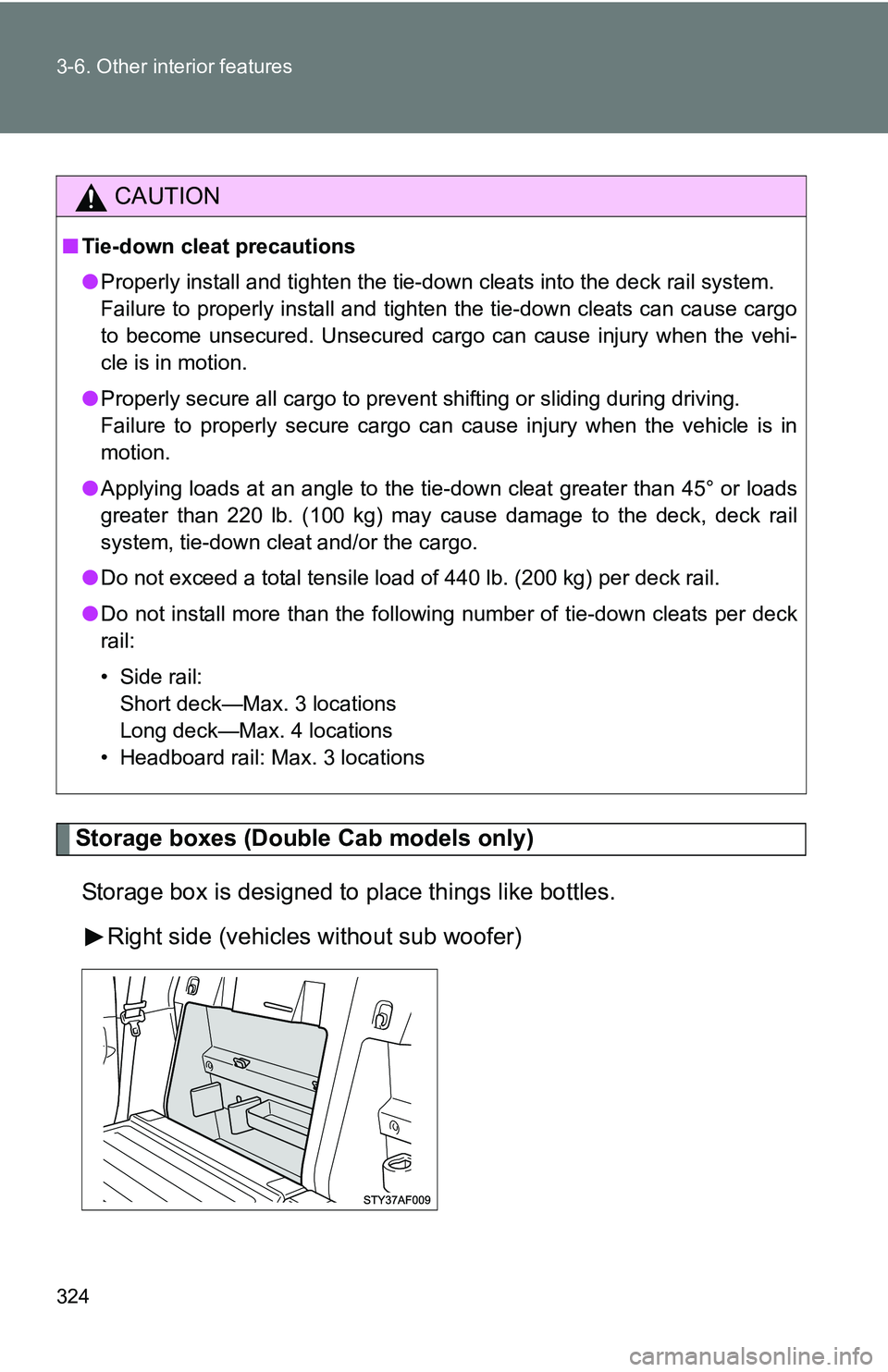
Storage boxes (Double Cab models only)Storage box is designed to place things like bottles. Right side (vehicles without sub woofer)
CAUTION
■Tie-down cleat precautions
●Properly install and tighten the tie-down cleats into the deck rail system.
Failure to properly install and tighten the tie-down cleats can cause cargo
to become unsecured. Unsecured cargo can cause injury when the vehi-
cle is in motion.
● Properly secure all cargo to prevent shifting or sliding during driving.
Failure to properly secure cargo can cause injury when the vehicle is in
motion.
● Applying loads at an angle to the tie- down cleat greater than 45° or loads
greater than 220 lb. (100 kg) may cause damage to the deck, deck rail
system, tie-down cleat and/or the cargo.
● Do not exceed a total tensile load of 440 lb. (200 kg) per deck rail.
● Do not install more than the following number of tie-down cleats per deck
rail:
• Side rail:
Short deck—Max. 3 locations
Long deck—Max. 4 locations
• Headboard rail: Max. 3 locations
Page 325 of 520
325
3-6. Other interior features
3
Interior and exterior features
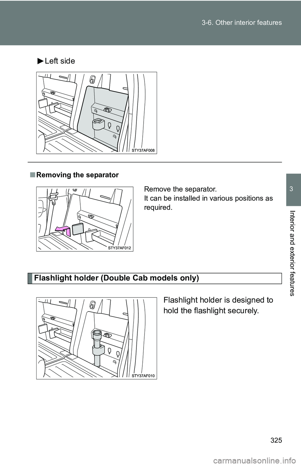
Left side
Flashlight holder (Doub
le Cab models only)
Flashlight holder is designed to
hold the flashlight securely.
■Removing the separator
Remove the separator.
It can be installed in various positions as
required.
Page 326 of 520
326 3-6. Other interior features
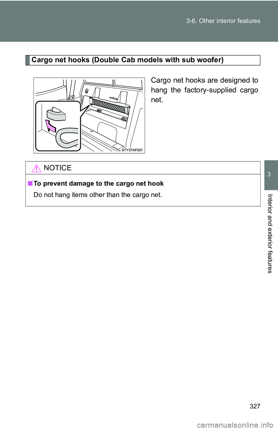
Grocery bag hooks (Double Cab models only)
Grocery bag hook is designed to
hang things like grocery bag.
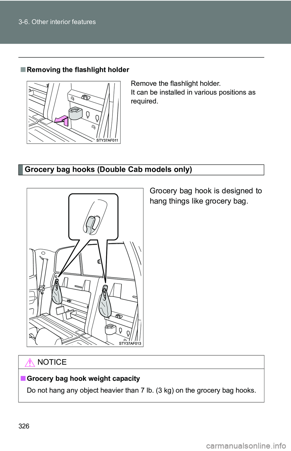
■Removing the flashlight holder
Remove the flashlight holder.
It can be installed in various positions as
required.
NOTICE
■Grocery bag hook weight capacity
Do not hang any object heavier than 7 lb. (3 kg) on the grocery bag hooks.
Page 327 of 520
327
3-6. Other interior features
3
Interior and exterior features
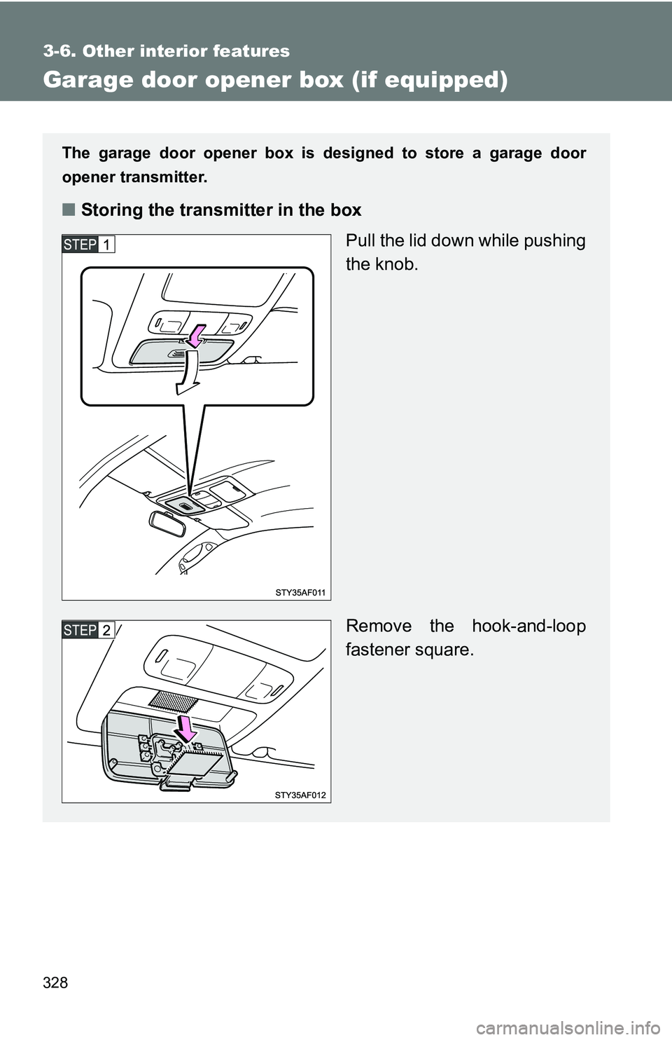
Cargo net hooks (Double Cab models with sub woofer)
Cargo net hooks are designed to
hang the factory-supplied cargo
net.
NOTICE
■
To prevent damage to the cargo net hook
Do not hang items other than the cargo net.
Page 328 of 520
328
3-6. Other interior features
Garage door opener box (if equipped)
The garage door opener box is designed to store a garage door
opener transmitter.
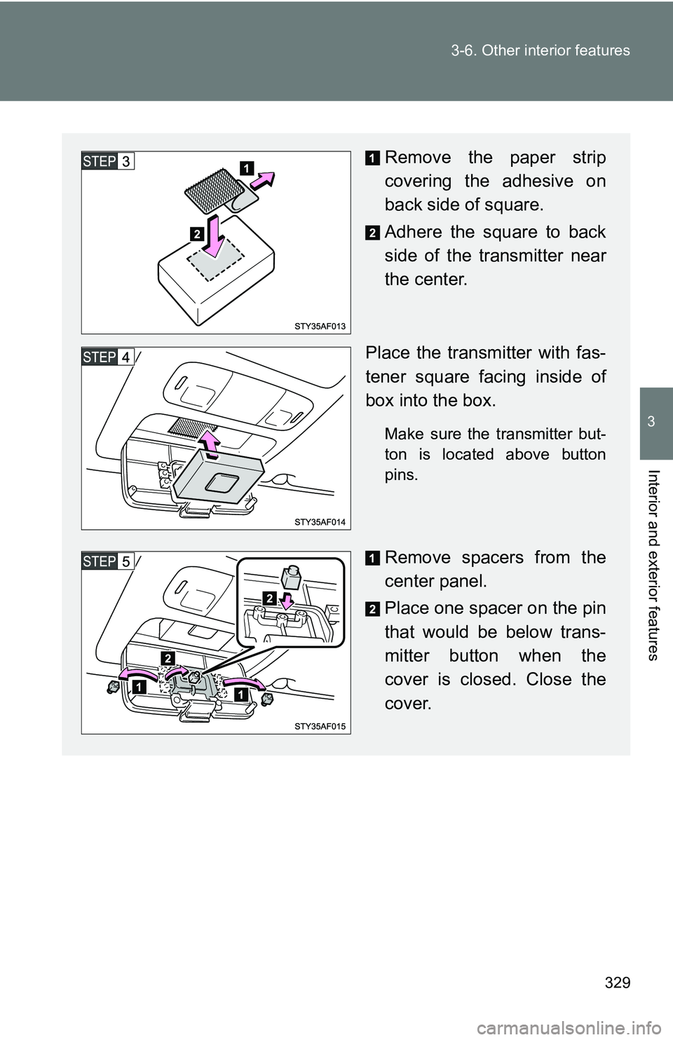
■Storing the transmitter in the box
Pull the lid down while pushing
the knob.
Remove the hook-and-loop
fastener square.
Page 329 of 520
329
3-6. Other interior features
3
Interior and exterior features
Remove the paper strip
covering the adhesive on
back side of square.
Adhere the square to back
side of the transmitter near
the center.
Place the transmitter with fas-
tener square facing inside of
box into the box.
Make sure the transmitter but-
ton is located above button
pins.
Remove spacers from the
center panel.
Place one spacer on the pin
that would be below trans-
mitter button when the
cover is closed. Close the
cover.
Page 330 of 520
330 3-6. Other interior features
■If a garage door opener transmi tter has wire clip for sun visor
■ If the center panel does not touch your garage door opener transmitter
■ To prevent the transmitter from clattering during driving
If the transmitter is clattering during driving, fill in a piece of felt or pad.
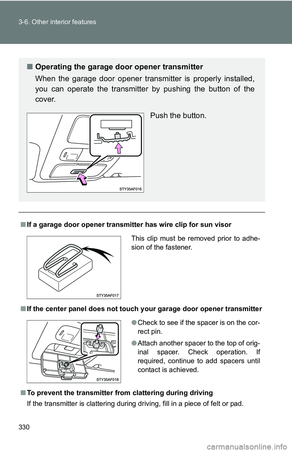
■ Operating the garage door opener transmitter
When the garage door opener transmitter is properly installed,
you can operate the transmitter by pushing the button of the
cover.
Push the button.
This clip must be removed prior to adhe-
sion of the fastener.
●Check to see if the spacer is on the cor-
rect pin.
● Attach another spacer to the top of orig-
inal spacer. Check operation. If
required, continue to add spacers until
contact is achieved.
Trending: driver seat adjustment, charging, heating, mirror, turn signal bulb, wheelbase, seats
