YAMAHA VX110 2005 Service Manual
Manufacturer: YAMAHA, Model Year: 2005, Model line: VX110, Model: YAMAHA VX110 2005Pages: 347, PDF Size: 14.17 MB
Page 191 of 347

5-92
EPOWRCONNECTING RODS AND PISTONS
9. Tighten:
Connecting rod nuts
WARNING
Replace the connecting rod bolts and
nuts with new ones.
Clean the connecting rod bolts and nuts.
NOTE:
The tightening procedure of the connecting rod
nuts is angle controlled, therefore tighten the
nuts using the following procedure.
Tightening steps:
Tighten the connecting rod nuts to the
specified torque.
T R..
Connecting rod nut:
1st:
20 N m (2.0 kgf m, 14 ft lb)
Tighten the connecting rod nuts further to
reach the specified angle 120°.
T R..
Connecting rod nut:
Final:
Specified angle 120
± 5°
WARNING
When the nuts are tightened more than
the specified angle, do not loosen the
nut and then retighten it.
Replace the bolt and nut with a new one
and perform the procedure again.
CAUTION:
Do not use a torque wrench to tighten
the nut to the specified angle.
Tighten the nut until it is at the speci-
fied angle.
NOTE:
When using a hexagonal nut, note that the
angle from one corner to another is 60°.
ProCarManuals.com
Page 192 of 347
5-93
EPOWRCRANKSHAFT
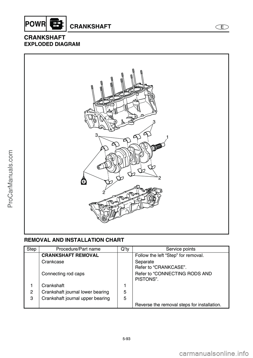
CRANKSHAFT
EXPLODED DIAGRAM
REMOVAL AND INSTALLATION CHART
Step Procedure/Part name Q’ty Service points
CRANKSHAFT REMOVAL
Follow the left “Step” for removal.
Crankcase Separate
Refer to “CRANKCASE”.
Connecting rod caps Refer to “CONNECTING RODS AND
PISTONS”.
1 Crankshaft 1
2 Crankshaft journal lower bearing 5
3 Crankshaft journal upper bearing 5
Reverse the removal steps for installation.
2
21 33E
ProCarManuals.com
Page 193 of 347
5-94
EPOWRCRANKSHAFT
SERVICE POINTS
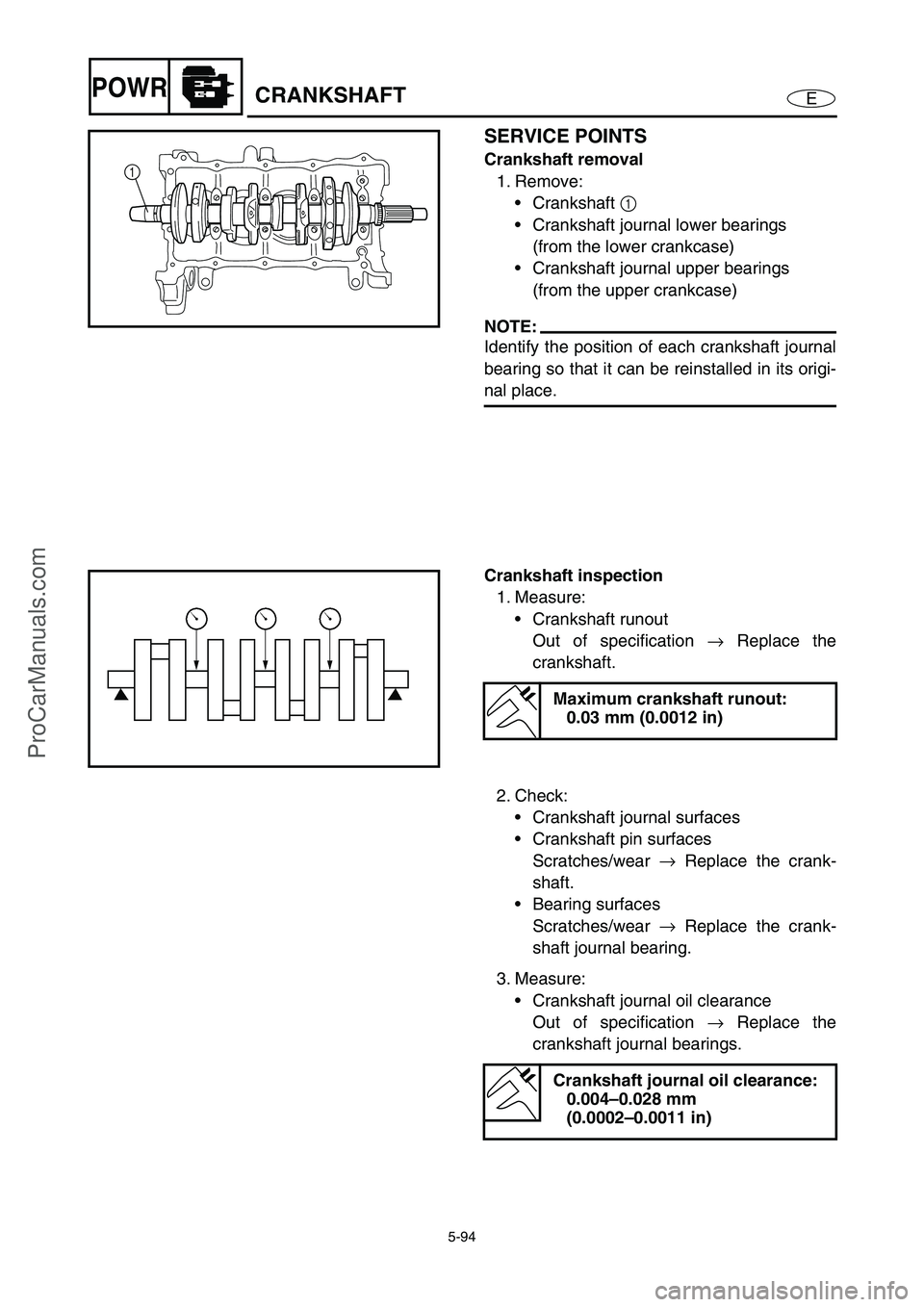
Crankshaft removal
1. Remove:
Crankshaft 1
Crankshaft journal lower bearings
(from the lower crankcase)
Crankshaft journal upper bearings
(from the upper crankcase)
NOTE:
Identify the position of each crankshaft journal
bearing so that it can be reinstalled in its origi-
nal place.
1
Crankshaft inspection
1. Measure:
Crankshaft runout
Out of specification →
Replace the
crankshaft.
Maximum crankshaft runout:
0.03 mm (0.0012 in)
2. Check:
Crankshaft journal surfaces
Crankshaft pin surfaces
Scratches/wear →
Replace the crank-
shaft.
Bearing surfaces
Scratches/wear →
Replace the crank-
shaft journal bearing.
3. Measure:
Crankshaft journal oil clearance
Out of specification →
Replace the
crankshaft journal bearings.
Crankshaft journal oil clearance:
0.004–0.028 mm
(0.0002–0.0011 in)
ProCarManuals.com
Page 194 of 347

5-95
EPOWRCRANKSHAFT
CAUTION:
Do not interchange the crankshaft journal
bearings. To obtain the correct crankshaft
journal oil clearance and prevent engine
damage, the crankshaft journal bearings
must be installed in their original positions.
Measurement steps:
Clean the crankshaft journal bearings,
crankshaft journals, and bearing portions
of the crankcase.
Place the upper crankcase upside down
on a bench.
Install the crankshaft journal upper bear-
ings 1
and the crankshaft into the upper
crankcase.
NOTE:
Align the projections a
of the crankshaft
journal upper bearings with the notches b
in the upper crankcase.
Put a piece of Plastigauge 2
on each
crankshaft journal.
NOTE:
Do not put the Plastigauge over the oil hole
in the crankshaft journal.
Install the crankshaft journal lower bear-
ings into the lower crankcase and assem-
ble the crankcase halves.
NOTE:
Align the projections a
of the crankshaft
journal lower bearings with the notches b
in the lower crankcase.
Do not move the crankshaft until the
clearance measurement has been com-
pleted.
1
a
b
2
ProCarManuals.com
Page 195 of 347

5-96
EPOWRCRANKSHAFT
Tighten the bolts to specification in the
order of the numbers on the crankcase.
Refer to “Crankcase assembly”—
“CRANKCASE”.
Remove the lower crankcase and the
crankshaft journal lower bearings.
Measure the compressed Plastigauge
width c
on each crankshaft journal.
If the crankshaft journal oil clearance is
out of specification, select replacement
crankshaft journal bearings.
c
4. Select:
Crankshaft journal bearings (J
1–J5)
NOTE:
The numbers stamped into the crankshaft
web and the numbers stamped into the lower
crankcase are used to determine the
replacement crankshaft journal bearing
sizes.
“J
1–J5” refer to the bearings shown in the
crankshaft illustration.
If “J
1–J5” are the same, use the same size
for all of the bearings.
For example, if the crankcase “J
1” and crank-
shaft web “J
1” numbers are “8” and “2” respec-
tively, then the bearing size for “J
1” is:
Bearing size of J
1:
“J
1” (crankcase) – “J1” (crankshaft web)
– 1
8 – 2 – 1 = 5 (Red/black)
BEARING COLOR CODE
3 Red/red
4Red/brown
5 Red/black
6 Red/blue
7Red/green
J5J4J3J2J1
J1J2J3J4J5
J5J4J3J2J1
ProCarManuals.com
Page 196 of 347

5-97
EPOWRCRANKSHAFT
Crankshaft installation
1. Install:
Crankshaft journal upper bearings
(into the upper crankcase)
Crankshaft journal lower bearings
(into the lower crankcase)
NOTE:
Align the projections a
on the crankshaft
journal upper bearings with the notches b
in
the upper crankcase.
Be sure to install each crankshaft journal
bearing in its original place.
a
b
2. Lubricate:
Crankshaft journals
Crankshaft journal bearings
(with the recommended lubricant)
Recommended lubricant:
Engine oil
ProCarManuals.com
Page 197 of 347
5-98
EPOWRCOOLING WATER HOSE
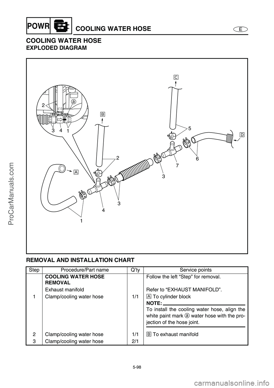
COOLING WATER HOSE
EXPLODED DIAGRAM
REMOVAL AND INSTALLATION CHART
Step Procedure/Part name Q’ty Service points
COOLING WATER HOSE
REMOVALFollow the left “Step” for removal.
Exhaust manifold Refer to “EXHAUST MANIFOLD”.
1 Clamp/cooling water hose 1/1È
To cylinder block
NOTE:
To install the cooling water hose, align the
white paint mark a
water hose with the pro-
jection of the hose joint.
2 Clamp/cooling water hose 1/1É
To exhaust manifold
3 Clamp/cooling water hose 2/1
143 2
375
6
ÈÉÊ
Ë
a
2
34
1
ProCarManuals.com
Page 198 of 347
5-99
EPOWRCOOLING WATER HOSE
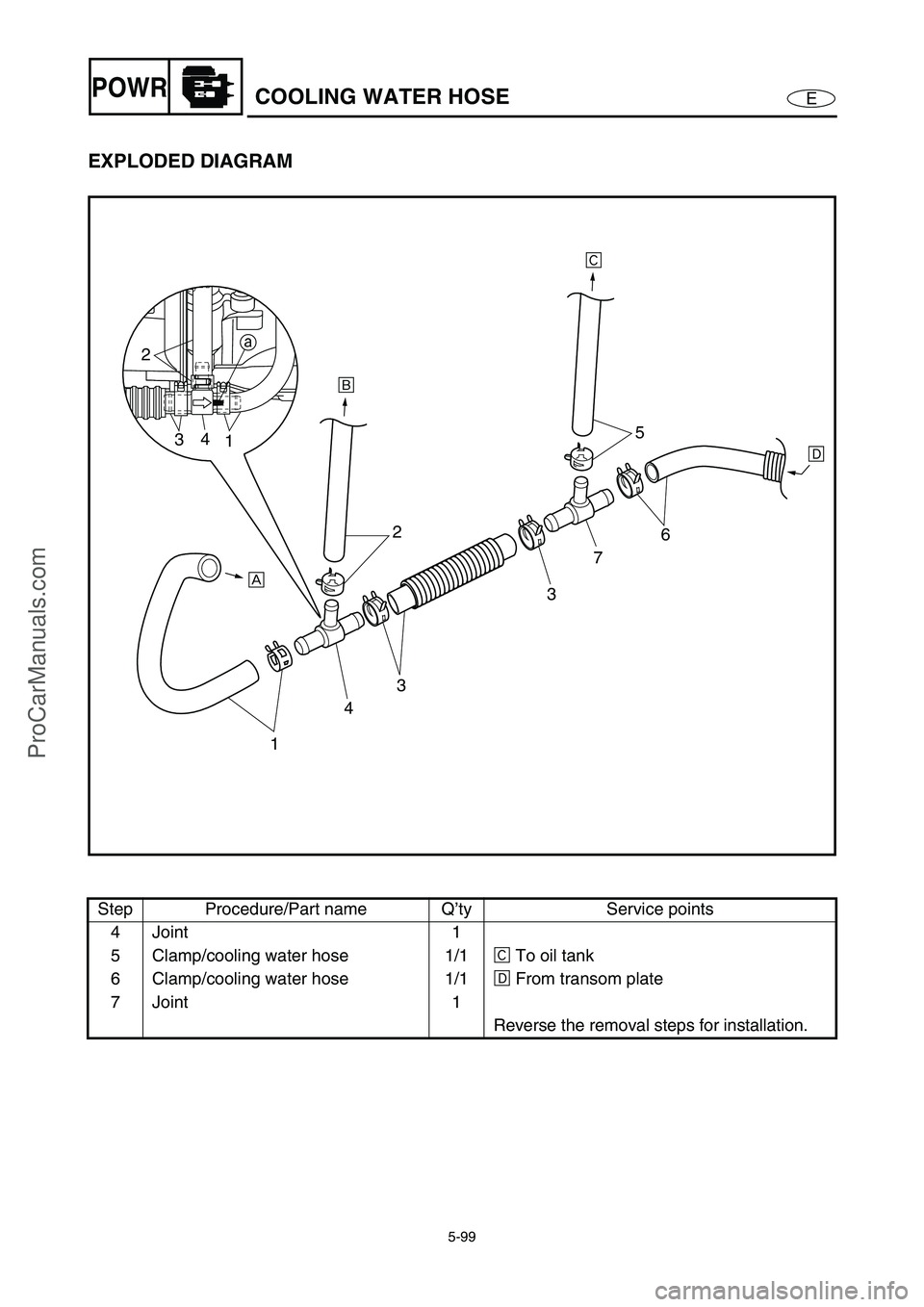
EXPLODED DIAGRAM
Step Procedure/Part name Q’ty Service points
4 Joint 1
5 Clamp/cooling water hose 1/1Ê
To oil tank
6 Clamp/cooling water hose 1/1Ë
From transom plate
7 Joint 1
Reverse the removal steps for installation.
143 2
375
6
ÈÉÊ
Ë
a
2
34
1
ProCarManuals.com
Page 199 of 347
E
JET
PUMP
1
2
3
4
5
6
7
8
9
CHAPTER 6
JET PUMP UNIT
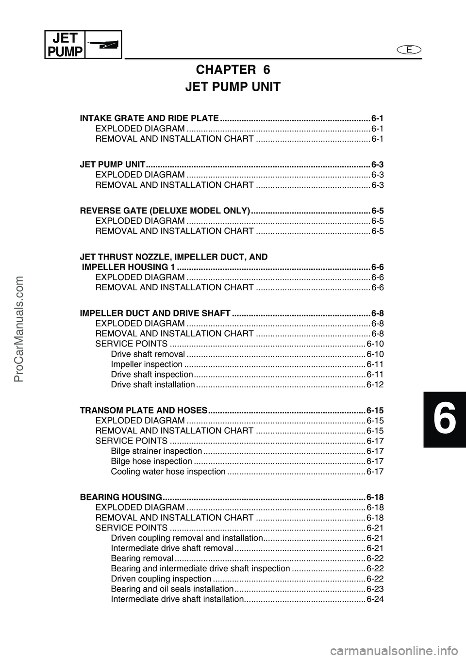
INTAKE GRATE AND RIDE PLATE ............................................................... 6-1
EXPLODED DIAGRAM ............................................................................. 6-1
REMOVAL AND INSTALLATION CHART ................................................ 6-1
JET PUMP UNIT .............................................................................................. 6-3
EXPLODED DIAGRAM ............................................................................. 6-3
REMOVAL AND INSTALLATION CHART ................................................ 6-3
REVERSE GATE (DELUXE MODEL ONLY) .................................................. 6-5
EXPLODED DIAGRAM ............................................................................. 6-5
REMOVAL AND INSTALLATION CHART ................................................ 6-5
JET THRUST NOZZLE, IMPELLER DUCT, AND
IMPELLER HOUSING 1 ................................................................................. 6-6
EXPLODED DIAGRAM ............................................................................. 6-6
REMOVAL AND INSTALLATION CHART ................................................ 6-6
IMPELLER DUCT AND DRIVE SHAFT .......................................................... 6-8
EXPLODED DIAGRAM ............................................................................. 6-8
REMOVAL AND INSTALLATION CHART ................................................ 6-8
SERVICE POINTS .................................................................................. 6-10
Drive shaft removal ........................................................................... 6-10
Impeller inspection ............................................................................ 6-11
Drive shaft inspection ........................................................................ 6-11
Drive shaft installation ....................................................................... 6-12
TRANSOM PLATE AND HOSES .................................................................. 6-15
EXPLODED DIAGRAM ........................................................................... 6-15
REMOVAL AND INSTALLATION CHART .............................................. 6-15
SERVICE POINTS .................................................................................. 6-17
Bilge strainer inspection .................................................................... 6-17
Bilge hose inspection ........................................................................ 6-17
Cooling water hose inspection .......................................................... 6-17
BEARING HOUSING ..................................................................................... 6-18
EXPLODED DIAGRAM ........................................................................... 6-18
REMOVAL AND INSTALLATION CHART .............................................. 6-18
SERVICE POINTS .................................................................................. 6-21
Driven coupling removal and installation........................................... 6-21
Intermediate drive shaft removal ....................................................... 6-21
Bearing removal ................................................................................ 6-22
Bearing and intermediate drive shaft inspection ............................... 6-22
Driven coupling inspection ................................................................ 6-22
Bearing and oil seals installation ....................................................... 6-23
Intermediate drive shaft installation................................................... 6-24
ProCarManuals.com
Page 200 of 347

6-1
E
JET
PUMP
INTAKE GRATE AND RIDE PLATE
EXPLODED DIAGRAM
REMOVAL AND INSTALLATION CHART
Step Procedure/Part name Q’ty Service points
INTAKE GRATE, RIDE PLATE,
AND INTAKE DUCT REMOVALFollow the left “Step” for removal.
1Bolt 2
2Bolt 2
3 Intake grate 1
4Screw 4
5 Speed sensor 1
NOTE:
Route the speed sensor lead between the
jet pump unit and the bilge hose.
INTAKE GRATE AND RIDE PLATE
ProCarManuals.com