YAMAHA VX110 2005 Service Manual
VX110 2005
YAMAHA
YAMAHA
https://www.carmanualsonline.info/img/51/57494/w960_57494-0.png
YAMAHA VX110 2005 Service Manual
Trending: oil capacity, fuel tank capacity, ECO mode, window, drain bolt, key, gas type
Page 201 of 347
6-2
E
JET
PUMPINTAKE GRATE AND RIDE PLATE
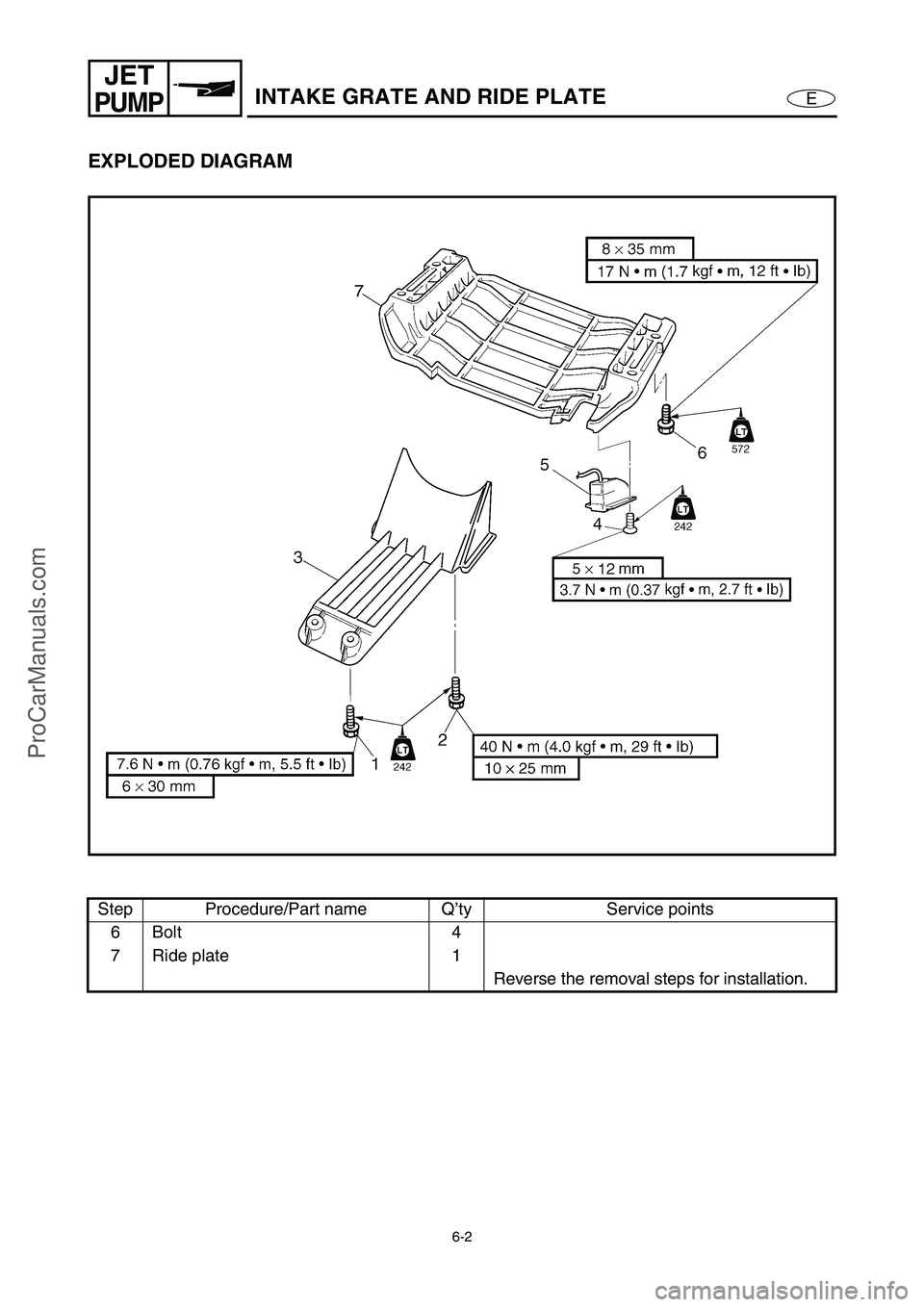
EXPLODED DIAGRAM
Step Procedure/Part name Q’ty Service points
6Bolt 4
7 Ride plate 1
Reverse the removal steps for installation.
ProCarManuals.com
Page 202 of 347
6-3
E
JET
PUMPJET PUMP UNIT
JET PUMP UNIT
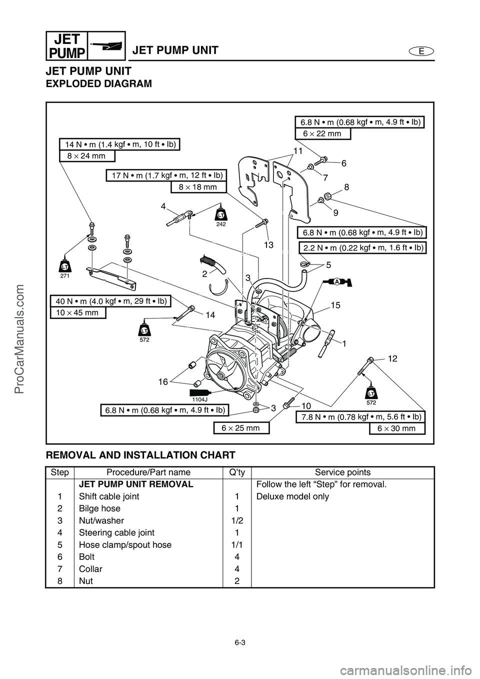
EXPLODED DIAGRAM
REMOVAL AND INSTALLATION CHART
Step Procedure/Part name Q’ty Service points
JET PUMP UNIT REMOVAL
Follow the left “Step” for removal.
1 Shift cable joint 1 Deluxe model only
2 Bilge hose 1
3 Nut/washer 1/2
4 Steering cable joint 1
5 Hose clamp/spout hose 1/1
6Bolt 4
7 Collar 4
8Nut 2
8 × 24 mm
14 N • m (1.4 kgf
• m, 10 ft
• Ib)
6 × 22 mm
6.8 N • m (0.68 kgf
• m, 4.9 ft
• Ib)
2.2 N • m (0.22 kgf
• m, 1.6 ft
• Ib)
6.8 N • m (0.68 kgf
• m, 4.9 ft
• Ib)
10 × 45 mm
40 N • m (4.0 kgf
• m, 29 ft
• Ib)
11
76
5
3
16
312 1 15
LT
572
LT
572
LT
572
LT
572
LT
242
AA
LT
271
LT
4
14
2
10
13
6.8 N • m (0.68 kgf
• m, 4.9 ft
• Ib)
8
9
6 × 30 mm
7.8 N •
m (0.78 kgf • m, 5.6 ft • Ib) 8 × 18 mm
17 N • m (1.7 kgf
• m, 12 ft
• Ib)
6 × 25 mm
1104J
ProCarManuals.com
Page 203 of 347
6-4
E
JET
PUMPJET PUMP UNIT
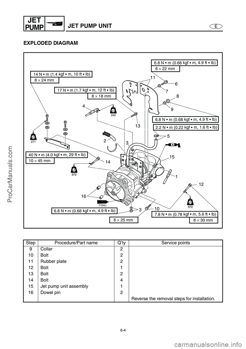
EXPLODED DIAGRAM
Step Procedure/Part name Q’ty Service points
9 Collar 2
10 Bolt 2
11 Rubber plate 2
12 Bolt 1
13 Bolt 2
14 Bolt 4
15 Jet pump unit assembly 1
16 Dowel pin 2
Reverse the removal steps for installation.
8 × 24 mm
14 N • m (1.4 kgf
• m, 10 ft
• Ib)
6 × 22 mm
6.8 N • m (0.68 kgf
• m, 4.9 ft
• Ib)
2.2 N • m (0.22 kgf
• m, 1.6 ft
• Ib)
6.8 N • m (0.68 kgf
• m, 4.9 ft
• Ib)
10 × 45 mm
40 N • m (4.0 kgf
• m, 29 ft
• Ib)
11
76
5
3
16
312 1 15
LT
572
LT
572
LT
572
LT
572
LT
242
AA
LT
271
LT
4
14
2
10
13
6.8 N • m (0.68 kgf
• m, 4.9 ft
• Ib)
8
9
6 × 30 mm
7.8 N •
m (0.78 kgf • m, 5.6 ft • Ib) 8 × 18 mm
17 N • m (1.7 kgf
• m, 12 ft
• Ib)
6 × 25 mm
1104J
ProCarManuals.com
Page 204 of 347
6-5
E
JET
PUMPREVERSE GATE (DELUXE MODEL ONLY)
REVERSE GATE (DELUXE MODEL ONLY)
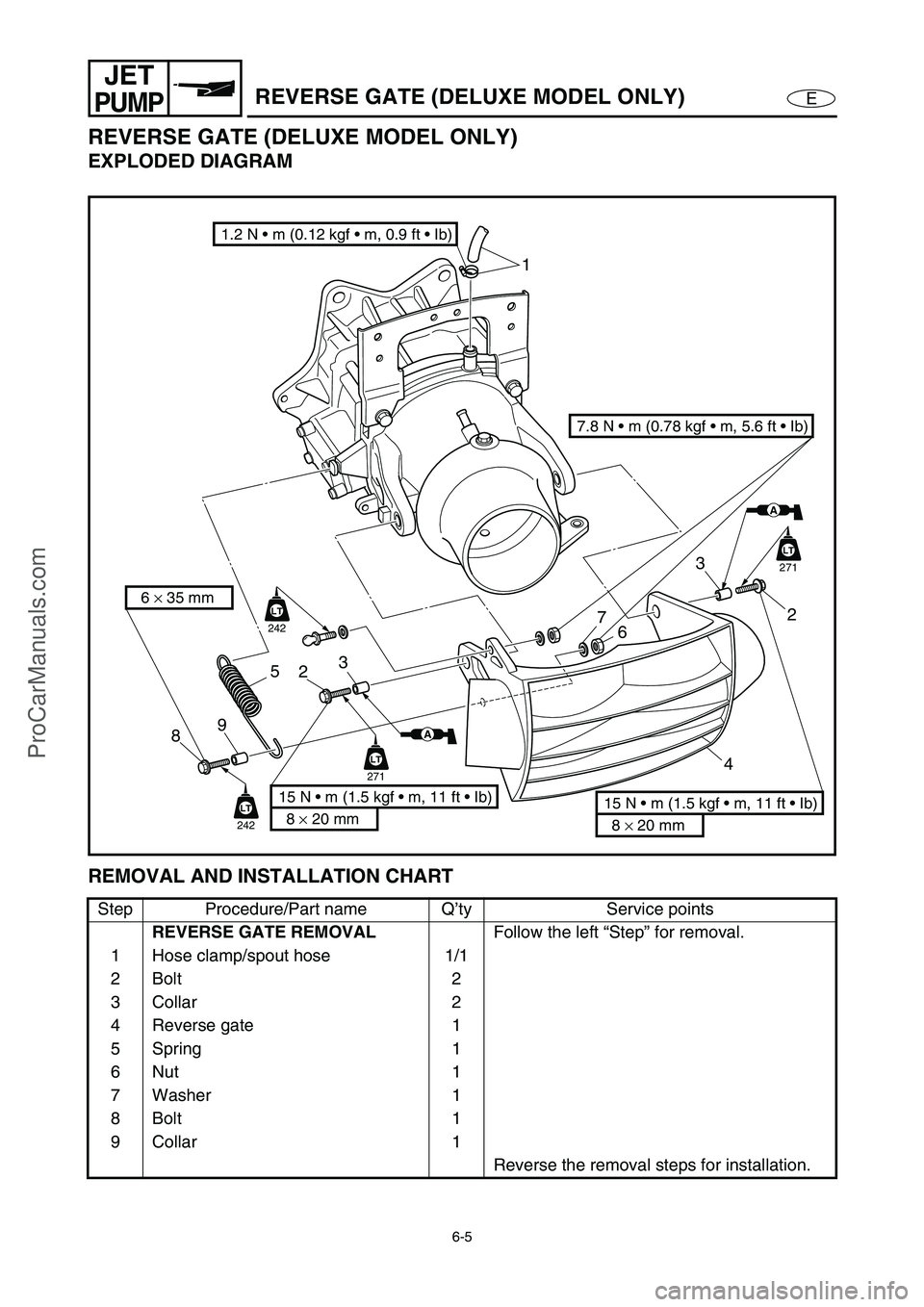
EXPLODED DIAGRAM
REMOVAL AND INSTALLATION CHART
Step Procedure/Part name Q’ty Service points
REVERSE GATE REMOVAL
Follow the left “Step” for removal.
1 Hose clamp/spout hose 1/1
2Bolt 2
3 Collar 2
4 Reverse gate 1
5Spring 1
6Nut 1
7 Washer 1
8Bolt 1
9 Collar 1
Reverse the removal steps for installation.
7.8 N • m (0.78 kgf • m, 5.6 ft • Ib)
1.2 N • m (0.12 kgf • m, 0.9 ft • Ib)
6 × 35 mm
8 × 20 mm
15 N • m (1.5 kgf • m, 11 ft • Ib)
AA
LT
271
LT
242
LT
242
LT
271
AA
3
2
7
6
23
5
9
81
4
8 × 20 mm
15 N • m (1.5 kgf • m, 11 ft • Ib)
ProCarManuals.com
Page 205 of 347
6-6
E
JET
PUMP
JET THRUST NOZZLE, IMPELLER DUCT, AND
IMPELLER HOUSING 1
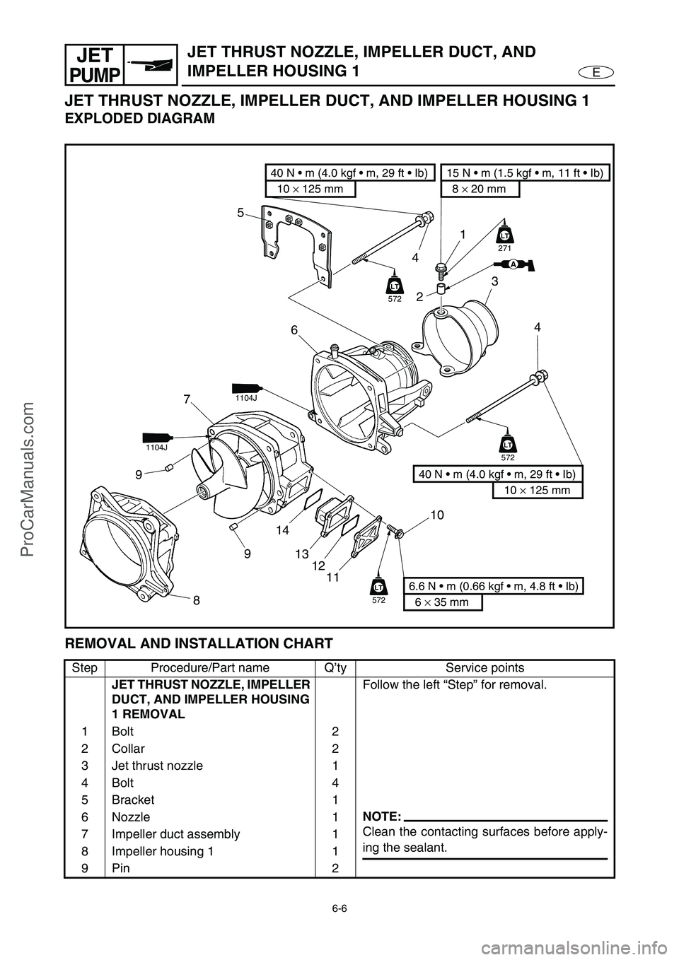
JET THRUST NOZZLE, IMPELLER DUCT, AND IMPELLER HOUSING 1
EXPLODED DIAGRAM
REMOVAL AND INSTALLATION CHART
Step Procedure/Part name Q’ty Service points
JET THRUST NOZZLE, IMPELLER
DUCT, AND IMPELLER HOUSING
1 REMOVALFollow the left “Step” for removal.
1Bolt 2
2 Collar 2
3 Jet thrust nozzle 1
4Bolt 4
5Bracket 1
6Nozzle 1
NOTE:
Clean the contacting surfaces before apply-
ing the sealant. 7 Impeller duct assembly 1
8 Impeller housing 1 1
9Pin 2
10 × 125 mm
40 N • m (4.0 kgf • m, 29 ft • Ib)
6 × 35 mm
6.6 N • m (0.66 kgf • m, 4.8 ft • Ib)
10
11 12 13 14
9 97
LT
572
LT
LT
572
LT
LT
572
LT
8
10 × 125 mm
40 N • m (4.0 kgf • m, 29 ft • Ib)
1
23
4
4
6 5
8 × 20 mm
15 N • m (1.5 kgf • m, 11 ft • Ib)
LT
271
AA
1104J
1104J
ProCarManuals.com
Page 206 of 347
6-7
E
JET
PUMP
JET THRUST NOZZLE, IMPELLER DUCT, AND
IMPELLER HOUSING 1
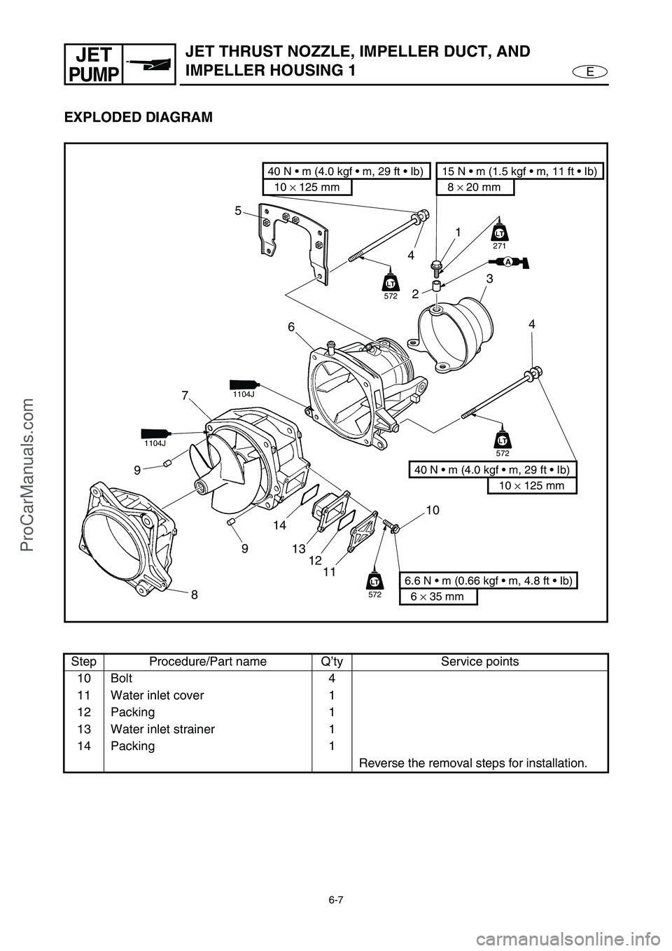
EXPLODED DIAGRAM
Step Procedure/Part name Q’ty Service points
10 Bolt 4
11 Water inlet cover 1
12 Packing 1
13 Water inlet strainer 1
14 Packing 1
Reverse the removal steps for installation.
10 × 125 mm
40 N • m (4.0 kgf • m, 29 ft • Ib)
6 × 35 mm
6.6 N • m (0.66 kgf • m, 4.8 ft • Ib)
10
11 12 13 14
9 97
LT
572
LT
LT
572
LT
LT
572
LT
8
10 × 125 mm
40 N • m (4.0 kgf • m, 29 ft • Ib)
1
23
4
4
6 5
8 × 20 mm
15 N • m (1.5 kgf • m, 11 ft • Ib)
LT
271
AA
1104J
1104J
ProCarManuals.com
Page 207 of 347
6-8
E
JET
PUMPIMPELLER DUCT AND DRIVE SHAFT
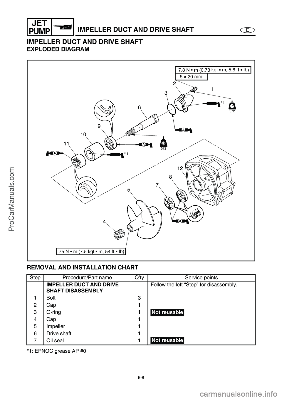
IMPELLER DUCT AND DRIVE SHAFT
EXPLODED DIAGRAM
REMOVAL AND INSTALLATION CHART
*1: EPNOC grease AP #0Step Procedure/Part name Q’ty Service points
IMPELLER DUCT AND DRIVE
SHAFT DISASSEMBLYFollow the left “Step” for disassembly.
1Bolt 3
2Cap 1
3 O-ring 1
4Cap 1
5 Impeller 1
6 Drive shaft 1
7 Oil seal 1
Not reusable
Not reusable
ProCarManuals.com
Page 208 of 347
6-9
E
JET
PUMPIMPELLER DUCT AND DRIVE SHAFT
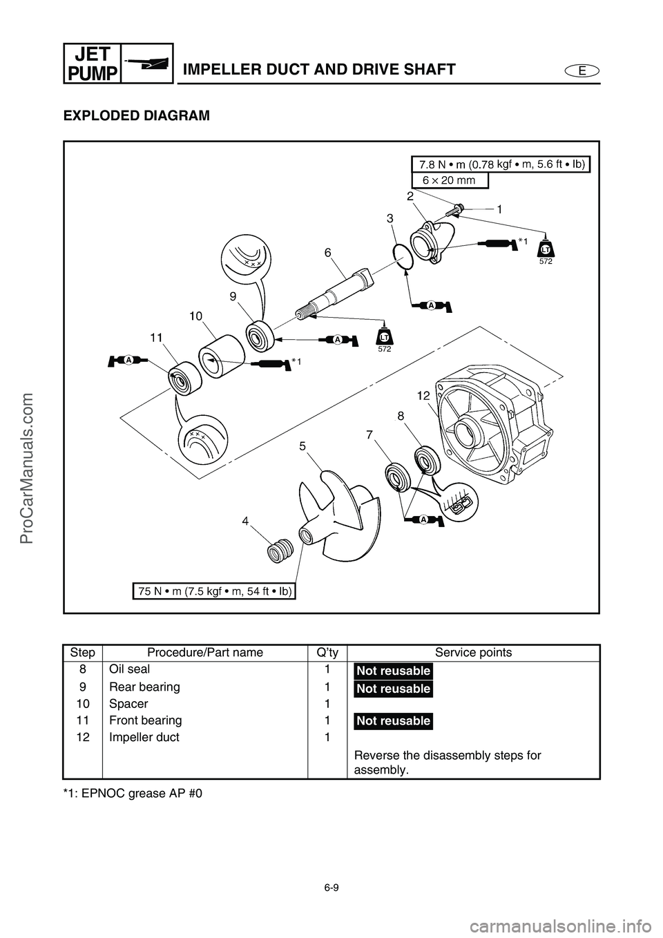
EXPLODED DIAGRAM
*1: EPNOC grease AP #0Step Procedure/Part name Q’ty Service points
8 Oil seal 1
9 Rear bearing 1
10 Spacer 1
11 Front bearing 1
12 Impeller duct 1
Reverse the disassembly steps for
assembly.
Not reusable
Not reusable
Not reusable
ProCarManuals.com
Page 209 of 347
6-10
E
JET
PUMPIMPELLER DUCT AND DRIVE SHAFT
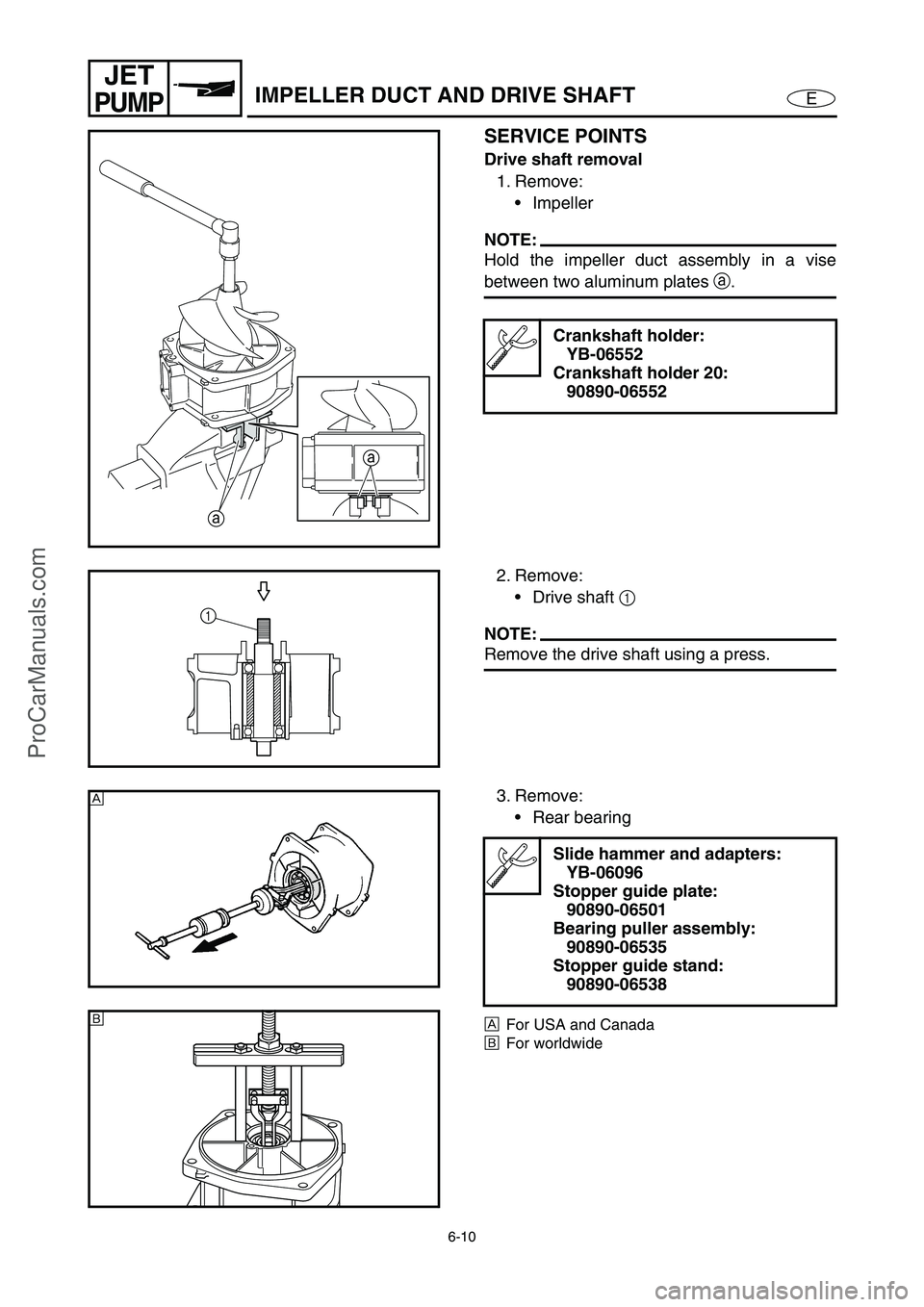
SERVICE POINTS
Drive shaft removal
1. Remove:
Impeller
NOTE:
Hold the impeller duct assembly in a vise
between two aluminum plates a
.
Crankshaft holder:
YB-06552
Crankshaft holder 20:
90890-06552
a
a
2. Remove:
Drive shaft 1
NOTE:
Remove the drive shaft using a press.
1
3. Remove:
Rear bearing
ÈFor USA and Canada
ÉFor worldwide
Slide hammer and adapters:
YB-06096
Stopper guide plate:
90890-06501
Bearing puller assembly:
90890-06535
Stopper guide stand:
90890-06538
È
É
ProCarManuals.com
Page 210 of 347
6-11
E
JET
PUMPIMPELLER DUCT AND DRIVE SHAFT
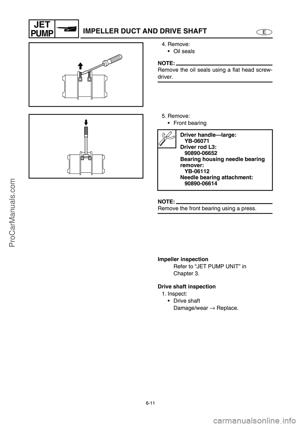
4. Remove:
Oil seals
NOTE:
Remove the oil seals using a flat head screw-
driver.
5. Remove:
Front bearing
NOTE:
Remove the front bearing using a press.
Driver handle—large:
YB-06071
Driver rod L3:
90890-06652
Bearing housing needle bearing
remover:
YB-06112
Needle bearing attachment:
90890-06614
Impeller inspection
Refer to “JET PUMP UNIT” in
Chapter 3.
Drive shaft inspection
1. Inspect:
Drive shaft
Damage/wear →
Replace.
ProCarManuals.com
Trending: USB port, oil change, fuel type, jump start, heating, fuel cap, engine overheat
