YAMAHA VX110 2005 Service Manual
Manufacturer: YAMAHA, Model Year: 2005, Model line: VX110, Model: YAMAHA VX110 2005Pages: 347, PDF Size: 14.17 MB
Page 181 of 347

5-82
EPOWRCONNECTING RODS AND PISTONS
SERVICE POINTS
Connecting rod and piston removal
The following procedure applies to all of the
connecting rods and pistons.
1. Remove:
Connecting rod cap 1
Big end bearings
NOTE:
Identify the position of each big end bearing so
that it can be reinstalled in its original place.
1
2. Remove:
Piston pin clips 1
Piston pin 2
Piston 3
Connecting rod 4
CAUTION:
Do not use a hammer to drive the piston
pin out.
NOTE:
For reference during installation, put an iden-
tification number a on the piston crown.
Before removing the piston pin, deburr the
piston pin clip’s groove and the piston’s pin
bore area.
3. Remove:
Top ring
2nd ring
Oil ring
NOTE:
When removing a piston ring, open the end
gap with your fingers and lift the other side of
the ring over the piston crown.
ProCarManuals.com
Page 182 of 347

5-83
EPOWRCONNECTING RODS AND PISTONS
Cylinder and piston inspection
The following procedure applies to all of the
cylinders and pistons.
1. Check:
Piston wall
Cylinder wall
Vertical scratches →
Replace the cylin-
der, and the piston and piston rings as a
set.
2. Measure:
Piston-to-cylinder clearance
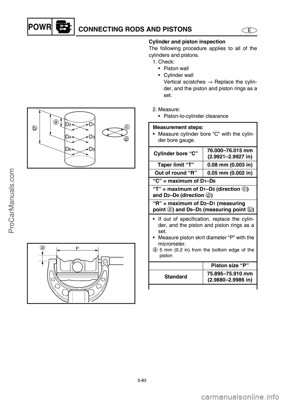
Measurement steps:
Measure cylinder bore “C” with the cylin-
der bore gauge.
Cylinder bore “C”76.000–76.015 mm
(2.9921–2.9927 in)
Taper limit “T”0.08 mm (0.003 in)
Out of round “R”0.05 mm (0.002 in)
“C” = maximum of D
1–D6
“T” = maximum of D
1–D5 (direction
c)
and D
2–D6 (direction
d)
“R” = maximum of D
2–D1 (measuring
point
a) and D
6–D5 (measuring point
b)
If out of specification, replace the cylin-
der, and the piston and piston rings as a
set.
Measure piston skirt diameter “P” with the
micrometer.
a
5 mm (0.2 in) from the bottom edge of the
piston
Piston size “P”
Standard75.895–75.910 mm
(2.9880–2.9986 in)
D1D2
D3D4
D5D6
c
d a
b
ProCarManuals.com
Page 183 of 347

5-84
EPOWRCONNECTING RODS AND PISTONS
If out of specification, replace the piston
and piston rings as a set.
Calculate the piston-to-cylinder clearance
with the following formula.
Piston-to-cylinder clearance = Cylinder
bore “C” – Piston skirt diameter “P”
Piston-to-cylinder clearance:
0.10–0.11 mm (0.0039–0.0043 in)
If out of specification, replace the piston
and piston rings as a set.
Piston ring inspection
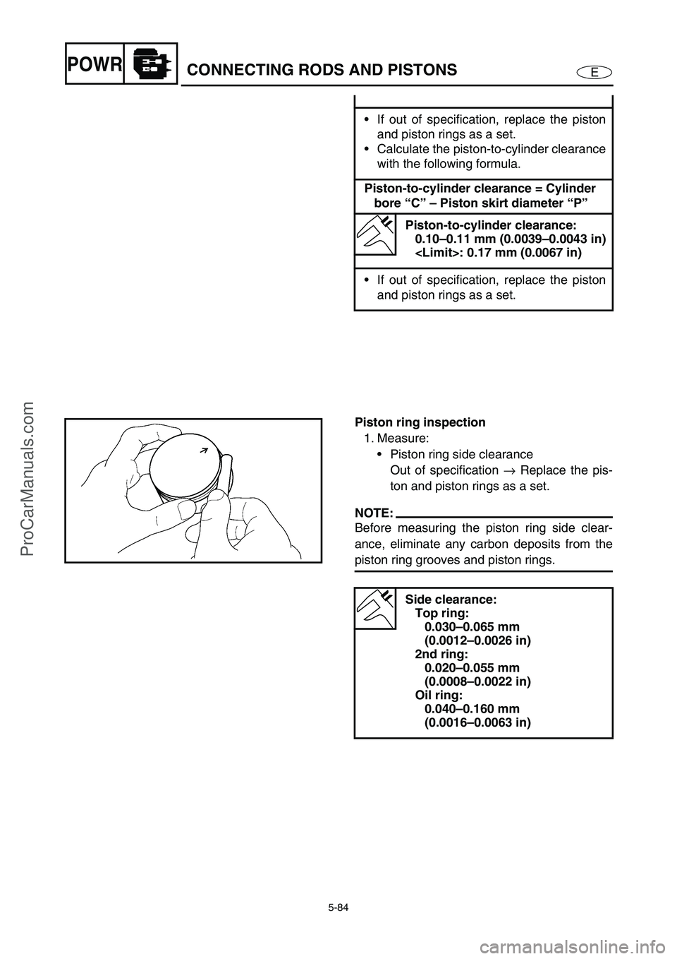
1. Measure:
Piston ring side clearance
Out of specification →
Replace the pis-
ton and piston rings as a set.
NOTE:
Before measuring the piston ring side clear-
ance, eliminate any carbon deposits from the
piston ring grooves and piston rings.
Side clearance:
Top ring:
0.030–0.065 mm
(0.0012–0.0026 in)
2nd ring:
0.020–0.055 mm
(0.0008–0.0022 in)
Oil ring:
0.040–0.160 mm
(0.0016–0.0063 in)
ProCarManuals.com
Page 184 of 347

5-85
EPOWRCONNECTING RODS AND PISTONS
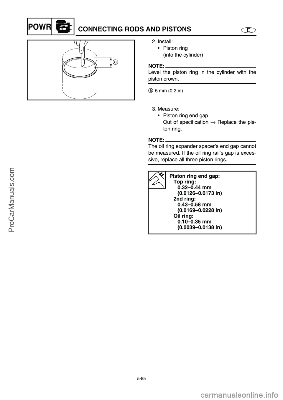
2. Install:
Piston ring
(into the cylinder)
NOTE:
Level the piston ring in the cylinder with the
piston crown.
a5 mm (0.2 in)
3. Measure:
Piston ring end gap
Out of specification →
Replace the pis-
ton ring.
NOTE:
The oil ring expander spacer’s end gap cannot
be measured. If the oil ring rail’s gap is exces-
sive, replace all three piston rings.
Piston ring end gap:
Top ring:
0.32–0.44 mm
(0.0126–0.0173 in)
2nd ring:
0.43–0.58 mm
(0.0169–0.0228 in)
Oil ring:
0.10–0.35 mm
(0.0039–0.0138 in)
ProCarManuals.com
Page 185 of 347

5-86
EPOWRCONNECTING RODS AND PISTONS
Piston pin inspection
The following procedure applies to all of the
piston pins.
1. Check:
Piston pin
Bluediscoloration/grooves →
Replace
the piston pin and then check the lubri-
cation system.
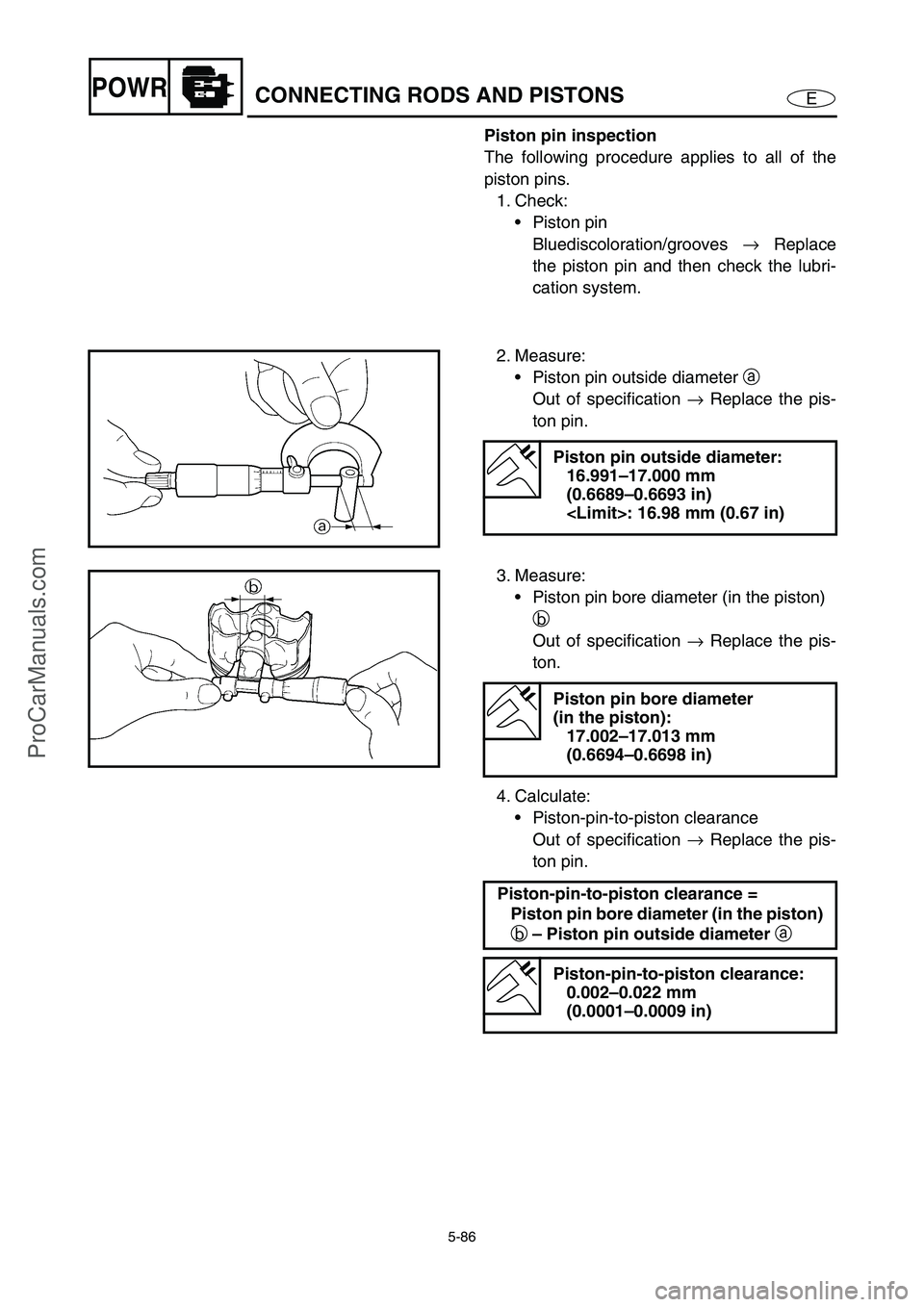
2. Measure:
Piston pin outside diameter a
Out of specification →
Replace the pis-
ton pin.
Piston pin outside diameter:
16.991–17.000 mm
(0.6689–0.6693 in)
3. Measure:
Piston pin bore diameter (in the piston)
b
Out of specification →
Replace the pis-
ton.
4. Calculate:
Piston-pin-to-piston clearance
Out of specification →
Replace the pis-
ton pin.
Piston pin bore diameter
(in the piston):
17.002–17.013 mm
(0.6694–0.6698 in)
Piston-pin-to-piston clearance =
Piston pin bore diameter (in the piston)
b – Piston pin outside diameter
a
Piston-pin-to-piston clearance:
0.002–0.022 mm
(0.0001–0.0009 in)
ProCarManuals.com
Page 186 of 347

5-87
EPOWRCONNECTING RODS AND PISTONS
Connecting rod inspection
1. Measure:
Big end oil clearance
Out of specification →
Replace the big
end bearings.
Big end oil clearance:
0.016–0.040 mm
(0.0006–0.0016 in)
Measurement steps:
The following procedure applies to all of the
connecting rods.
CAUTION:
Do not interchange the big end bearings
and connecting rods. To obtain the cor-
rect big end oil clearance and prevent
engine damage, the big end bearings
must be installed in their original posi-
tions.
Clean the big end bearings, crankshaft
pins, and the inside of the connecting rod
halves.
Install the big end upper bearing into the
connecting rod and the big end lower
bearing into the connecting rod cap.
NOTE:
Align the projections a
on the big end bear-
ings with the notches b
in the connecting
rod and connecting rod cap.
Put a piece of Plastigauge 1
on the
crankshaft pin.
Assemble the connecting rod halves.
1
ProCarManuals.com
Page 187 of 347

5-88
EPOWRCONNECTING RODS AND PISTONS
NOTE:
• Do not move the connecting rod or crank-
shaft until the clearance measurement
has been completed.
Lubricate the bolts threads and nut seats
with molybdenum disulfide grease.
Make sure the “Y” mark c on the con-
necting rod faces towards the front side of
the crankshaft.
Make sure the characters d on both the
connecting rod and connecting rod cap
are aligned.
Tighten the connecting rod nuts.
Refer to “Connecting rod and piston
installation”.
Remove the connecting rod and big end
bearings.
Refer to “Connecting rod and piston
removal”.
Measure the compressed Plastigauge
width e on the crankshaft pin.
If the big end oil clearance is out of speci-
fication, select replacement big end bear-
ings.
cd
e
2. Select:
Big end bearings (P
1–P4)
NOTE:
The numbers stamped into the crankshaft web
and the numbers on the connecting rods are
used to determine the replacement big end
bearing sizes.
P4
P3P2
P1
ProCarManuals.com
Page 188 of 347

5-89
EPOWRCONNECTING RODS AND PISTONS
For example, if the connecting rod “P1” and the
crankshaft web “P
1” numbers are “5” and “1”
respectively, then the bearing size for “P
1” is:
Bearing size of P
1:
“P
1” (connecting rod) –
“P
1” (crankshaft web)
5 – 1 = 4 (green)
BEARING COLOR CODE
1brown
2 black
3blue
4 green5 G
P4P3P2P1
Connecting rod and piston installation
The following procedure applies to all of the
pistons and connecting rods.
1. Install:
Oil ring
2nd ring
Top ring
NOTE:
Be sure to install the piston rings so that the
manufacturer’s marks or numbers face up.
2. Install:
Piston 1
Connecting rod 2
Piston pin 3
Piston pin clips 4
NOTE:
Apply engine oil onto the piston pin.
When installing the connecting rod to the pis-
ton, make sure that the “Y” mark a
on the
connecting rod faces towards the left when
the exhaust valve recesses b
on the piston
face upward. Refer to the illustration.
Reinstall each piston into its original cylinder
(numbering order starting from the front: #1
to #4).
ProCarManuals.com
Page 189 of 347

5-90
EPOWRCONNECTING RODS AND PISTONS
3. Offset:
Piston ring end gaps
aTop ring, oil ring expander spacer
b2nd ring, lower oil ring rail
cUpper oil ring rail
ÈExhaust sidebc
a È
90˚
45˚
90˚
4. Lubricate:
Piston
Piston rings
Cylinder
(with the recommended lubricant)
Recommended lubricant:
Engine oil
5. Lubricate:
Bolt threads
Nut seats
(with the recommended lubricant)
Recommended lubricant:
Molybdenum disulfide grease
6. Lubricate:
Crankshaft pins
Big end bearings
(with the recommended lubricant)
Recommended lubricant:
Engine oil
ProCarManuals.com
Page 190 of 347

5-91
EPOWRCONNECTING RODS AND PISTONS
7. Install:
Big end bearings
Connecting rod assembly 1
(into the cylinder and onto the
crankshaft pin)
Connecting rod cap
(onto the crankshaft pin)
NOTE:
Align the projections on the big end bearings
with the notches in the connecting rods and
connecting rod caps.
Be sure to reinstall each big end bearing in
its original place.
While compressing the piston rings with pis-
ton ring compressor 2
, install the connecting
rod assembly into the cylinder with the other
hand.
Make sure the “Y” marks a
on the connect-
ing rods face towards the front side of the
crankshaft.
Make sure the characters b
on both the con-
necting rod and connecting rod cap are
aligned.
8. Align:
Bolt heads
(with the connecting rod)
Piston ring compressor:
YM-08037/90890-05158
ProCarManuals.com