engine oil YAMAHA XSR 900 2022 User Guide
[x] Cancel search | Manufacturer: YAMAHA, Model Year: 2022, Model line: XSR 900, Model: YAMAHA XSR 900 2022Pages: 114, PDF Size: 4.36 MB
Page 69 of 114
Periodic maintenance and adjustment
7-6
1
2
3
4
5
678
9
10
11
12
13
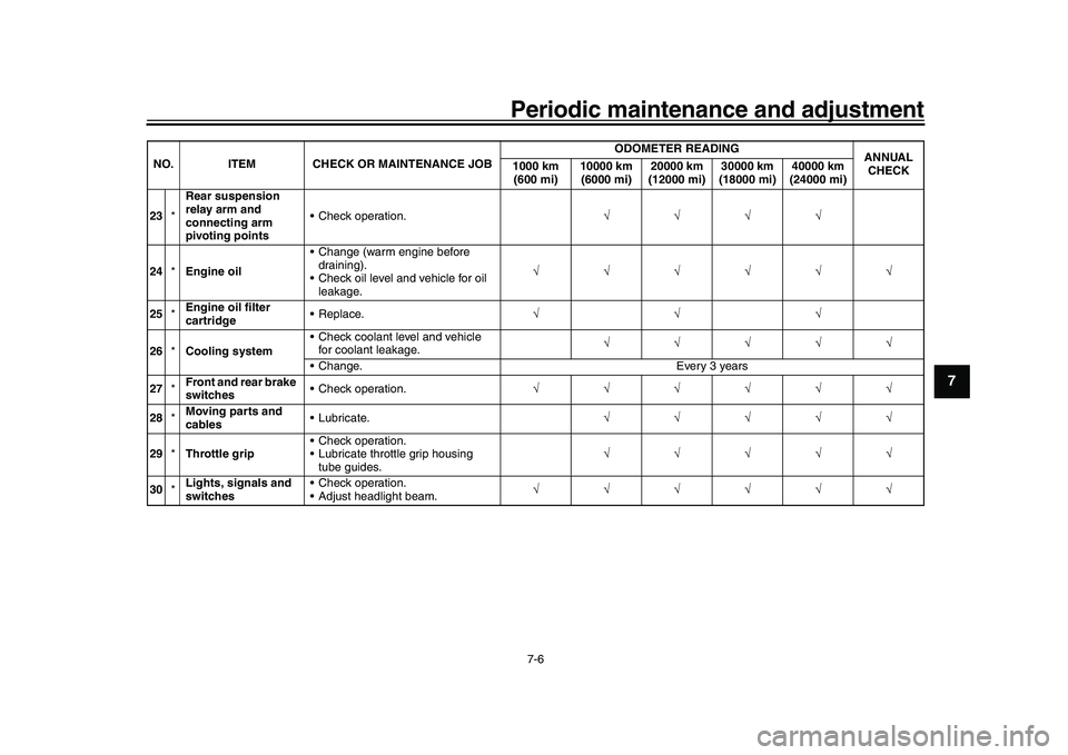
23 *Rear suspension
relay arm and
connecting arm
pivoting points Check operation.
24 *Engine oil Change (warm engine before
draining).
Check oil level and vehicle for oil leakage.
25 *Engine oil filter
cartridge Replace.
26 *Cooling system Check coolant level and vehicle
for coolant leakage.
Change. Every 3 years
27 *Front and rear brake
switches Check operation.
28 *Moving parts and
cables Lubricate.
29 *Throttle grip Check operation.
Lubricate throttle grip housing
tube guides.
30 *Lights, signals and
switches Check operation.
Adjust headlight beam.
NO. ITEM CHECK OR MAINTENANCE JOB
ODOMETER READING
ANNUAL
CHECK
1000 km
(600 mi) 10000 km
(6000 mi) 20000 km
(12000 mi) 30000 km
(18000 mi) 40000 km
(24000 mi)
BEA-28199-E0.book 6 ページ 2021年12月1日 水曜日 午後7時8分
Page 74 of 114

Periodic maintenance and adjustment
7-11
1
2
3
4
5
67
8
9
10
11
12
13
EAU19653
Checking the spark plugsThe spark plugs are important engine
components, which should be checked
periodically, preferably by a Yamaha
dealer. Since heat and deposits will
cause any spark plug to slowly erode,
they should be removed and checked
in accordance with the periodic mainte-
nance and lubrication chart. In addition,
the condition of the spark plugs can re-
veal the condition of the engine.
The porcelain insulator around the cen-
ter electrode of each spark plug should
be a medium-to-light tan (the ideal color
when the vehicle is ridden normally),
and all spark plugs installed in the en-
gine should have the same color. If any
spark plug shows a distinctly different
color, the engine could be operating im-
properly. Do not attempt to diagnose
such problems yourself. Instead, have
a Yamaha dealer check the vehicle.
If a spark plug shows signs of electrode
erosion and excessive carbon or other
deposits, it should be replaced. Before installing a spark plug, the spark
plug gap should be measured with a
wire thickness gauge and, if necessary,
adjusted to specification.
Clean the surface of the spark plug
gasket and its mating surface, and then
wipe off any grime from the spark plug
threads.
TIPIf a torque wrench is not available wheninstalling a spark plug, a good estimate
of the correct torque is 1/4–1/2 turn
past finger tight. However, the spark
plug should be tightened to the speci-
fied torque as soon as possible.NOTICE
ECA10841
Do not use any tools to remove or in-
stall the spark plug cap, otherwise
the ignition coil coupler may get
damaged. The spark plug cap may
be difficult to remove because the
rubber seal on the end of the cap fits
tightly. To remove the spark plug
cap, simply twist it back and forth
while pulling it out; to install it, twistit back and forth while pushing it in.
Specified spark plug:
NGK/LMAR9A-9
1. Spark plug gapSpark plug gap: 0.8–0.9 mm (0.031–0.035 in)
Tightening torque: Spark plug:13 N·m (1.3 kgf·m, 9.6 lb·ft)
BEA-28199-E0.book 11 ページ 2021年12月1日 水曜日 午後7時8分
Page 75 of 114
Periodic maintenance and adjustment7-12
1
2
3
4
5
678
9
10
11
12
13
EAU36113
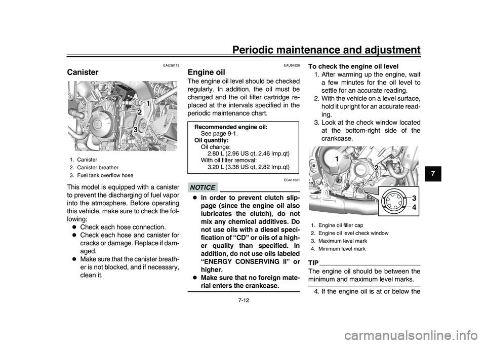
CanisterThis model is equipped with a canister
to prevent the discharging of fuel vapor
into the atmosphere. Before operating
this vehicle, make sure to check the fol-
lowing:
Check each hose connection.
Check each hose and canister for
cracks or damage. Replace if dam-
aged.
Make sure that the canister breath-
er is not blocked, and if necessary,
clean it.
EAU94920
Engine oilThe engine oil level should be checked
regularly. In addition, the oil must be
changed and the oil filter cartridge re-
placed at the intervals specified in the
periodic maintenance chart.NOTICE
ECA11621
In order to prevent clutch slip-
page (since the engine oil also
lubricates the clutch), do not
mix any chemical additives. Do
not use oils with a diesel speci-
fication of “CD” or oils of a high-
er quality than specified. In
addition, do not use oils labeled
“ENERGY CONSERVING II” or
higher.
Make sure that no foreign mate-rial enters the crankcase. To check the engine oil level
1. After warming up the engine, wait a few minutes for the oil level to
settle for an accurate reading.
2. With the vehicle on a level surface, hold it upright for an accurate read-
ing.
3. Look at the check window located at the bottom-right side of the
crankcase.
TIPThe engine oil should be between theminimum and maximum level marks.
4. If the engine oil is at or below the
1. Canister
2. Canister breather
3. Fuel tank overflow hose
1 1 1
2 2
3 3
Recommended engine oil: See page 9-1.
Oil quantity: Oil change:2.80 L (2.96 US qt, 2.46 Imp.qt)
With oil filter removal: 3.20 L (3.38 US qt, 2.82 Imp.qt)
1. Engine oil filler cap
2. Engine oil level check window
3. Maximum level mark
4. Minimum level mark
11
21
2
34
BEA-28199-E0.book 12 ページ 2021年12月1日 水曜日 午後7時8分
Page 76 of 114
Periodic maintenance and adjustment
7-13
1
2
3
4
5
67
8
9
10
11
12
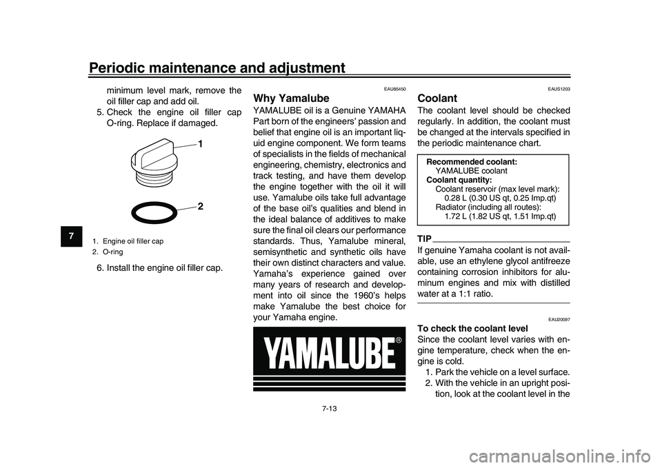
13 minimum level mark, remove the
oil filler cap and add oil.
5. Check the engine oil filler cap O-ring. Replace if damaged.
6. Install the engine oil filler cap.
EAU85450
Why YamalubeYAMALUBE oil is a Genuine YAMAHA
Part born of the engineers’ passion and
belief that engine oil is an important liq-
uid engine component. We form teams
of specialists in the fields of mechanical
engineering, chemistry, electronics and
track testing, and have them develop
the engine together with the oil it will
use. Yamalube oils take full advantage
of the base oil’s qualities and blend in
the ideal balance of additives to make
sure the final oil clears our performance
standards. Thus, Yamalube mineral,
semisynthetic and synthetic oils have
their own distinct characters and value.
Yamaha’s experience gained over
many years of research and develop-
ment into oil since the 1960’s helps
make Yamalube the best choice for
your Yamaha engine.
EAUS1203
CoolantThe coolant level should be checked
regularly. In addition, the coolant must
be changed at the intervals specified in
the periodic maintenance chart.TIPIf genuine Yamaha coolant is not avail-
able, use an ethylene glycol antifreeze
containing corrosion inhibitors for alu-
minum engines and mix with distilledwater at a 1:1 ratio.
EAU20097
To check the coolant level
Since the coolant level varies with en-
gine temperature, check when the en-
gine is cold. 1. Park the vehicle on a level surface.
2. With the vehicle in an upright posi- tion, look at the coolant level in the
1. Engine oil filler cap
2. O-ring
21
Recommended coolant:YAMALUBE coolant
Coolant quantity: Coolant reservoir (max level mark):0.28 L (0.30 US qt, 0.25 Imp.qt)
Radiator (including all routes): 1.72 L (1.82 US qt, 1.51 Imp.qt)
BEA-28199-E0.book 13 ページ 2021年12月1日 水曜日 午後7時8分
Page 88 of 114
Periodic maintenance and adjustment
7-25
1
2
3
4
5
67
8
9
10
11
12
13
EAU23027
Cleaning and l ubricating the
drive chainThe drive chain must be cleaned and
lubricated at the intervals specified in
the periodic maintenance and lubrica-
tion chart, otherwise it will quickly wear
out, especially when riding in dusty or
wet areas. Service the drive chain as
follows.NOTICE
ECA10584
The drive chain must be lubricated
after washing the motorcycle, ridingin the rain or riding in wet areas.
1. Clean the drive chain with a drive chain cleaner and a small soft
brush. NOTICE: To prevent dam-
aging the O-rings, do not clean
the drive chain with steam
cleaners, high-pressure wash-
ers or inappropriate sol-
vents.
[ECA11122]
2. Wipe the drive chain dry.
3. Thoroughly lubricate the drive chain with a special O-ring chain
lubricant. NOTICE: Do not use
engine oil or any other lubri- cants for the drive chain, as they
may contain substances that
could damage the O-rings.
[ECA11112]
EAU23098
Checking and lubricating the
cablesThe operation of all control cables and
the condition of the cables should be
checked before each ride, and the ca-
bles and cable ends should be lubricat-
ed if necessary. If a cable is damaged
or does not move smoothly, have a
Yamaha dealer check or replace it.
WARNING! Damage to the outer
housing of cables may result in in-
ternal rusting and cause interfer-
ence with cable movement. Replace
damaged cables as soon as possi-
ble to prevent unsafe condi-
tions.
[EWA10712]
Recommended lubricant:
Yamaha cable lubricant or other suit-
able cable lubricant
BEA-28199-E0.book 25 ページ 2021年12月1日 水曜日 午後7時8分
Page 104 of 114
Motorcycle care and storage
8-4
1
2
3
4
5
6
78
9
10
11
12
13 perform any outstanding mainte-
nance.
2. Follow all instructions in the Care section of this chapter.
3. Fill up the fuel tank, adding fuel stabilizer according to product in-
structions. Run the engine for 5
minutes to distribute treated fuel
through the fuel system.
4. For vehicles equipped with a fuel cock: Turn the fuel cock lever to
the off position.
5. For vehicles with a carburetor: To prevent fuel deposits from building
up, drain the fuel in the carburetor
float chamber into a clean contain-
er. Retighten the drain bolt and
pour the fuel back into the fuel
tank.
6. Use a quality engine fogging oil ac- cording to product instructions to
protect internal engine compo-
nents from corrosion. If engine fog-
ging oil is not available, perform
the following steps for each cylin-
der:
a. Remove the spark plug cap and spark plug.
b. Pour a teaspoonful of engine oil into the spark plug bore.
c. Install the spark plug cap onto the spark plug, and then place
the spark plug on the cylinder
head so that the electrodes are
grounded. (This will limit spark-
ing during the next step.)
d. Turn the engine over several times with the starter. (This will
coat the cylinder wall with oil.)
WARNING! To prevent dam-
age or injury from sparking,
make sure to ground the
spark plug electrodes while
turning the engine
over.
[EWA10952]
e. Remove the spark plug capfrom the spark plug, and then
install the spark plug and the
spark plug cap.
7. Lubricate all control cables, pivots, levers and pedals, as well as the
sidestand and centerstand (if
equipped).
8. Check and correct the tire air pres- sure, and then lift the vehicle so
that all wheels are off the ground.
Otherwise, turn the wheels a little
once a month in order to prevent the tires from becoming degraded
in one spot.
9. Cover the muffler outlet with a plastic bag to prevent moisture
from entering it.
10. Remove the battery and fully charge it, or attach a maintenance
charger to keep the battery opti-
mally charged. NOTICE: Confirm
that the battery and its charger
are compatible. Do not charge a
VRLA battery with a convention-
al charger.
[ECA26330]
TIP
If the battery will be removed,
charge it once a month and store it
in a temperate location between
0-30 C (32-90 F).
See page 7-29 for more informa-
tion on charging and storing thebattery.
BEA-28199-E0.book 4 ページ 2021年12月1日 水曜日 午後7時8分
Page 105 of 114

9-1
1
2
3
4
5
6
7
8910
11
12
13
Specifications
EAU84806
Dimensions:Overall length:2155 mm (84.8 in)
Overall width: 860 mm (33.9 in)
Overall height: 1155 mm (45.5 in)
Seat height:
810 mm (31.9 in)
Wheelbase: 1495 mm (58.9 in)
Ground clearance: 140 mm (5.51 in)
Minimum turning radius:
3.5 m (11.48 ft)Weight:Curb weight:193 kg (425 lb)Engine:Combustion cycle:4-stroke
Cooling system: Liquid cooled
Valve train:
DOHC
Cylinder arrangement: Inline
Number of cylinders: 3-cylinder
Displacement:
890 cm
3
Bore stroke:
78.0 62.1 mm (3.07 2.44 in) Starting system:
Electric starter
Engine oil:Recommended brand:
SAE viscosity grades:10W-40
Recommended engine oil grade: API service SG type or higher, JASO stan-
dard MA
Engine oil quantity: Oil change:2.80 L (2.96 US qt, 2.46 Imp.qt)
With oil filter removal: 3.20 L (3.38 US qt, 2.82 Imp.qt)Coolant quantity:Coolant reservoir (up to the maximum level
mark):
0.28 L (0.30 US qt, 0.25 Imp.qt)
Radiator (including all routes): 1.72 L (1.82 US qt, 1.51 Imp.qt)Fuel:Recommended fuel:
Unleaded gasoline (E10 acceptable)
Octane number (RON): 95
Fuel tank capacity: 14 L (3.7 US gal, 3.1 Imp.gal)
Fuel reserve amount:
2.7 L (0.71 US gal, 0.59 Imp.gal)
Fuel injection:Throttle body:ID mark:B7N1Drivetrain:Gear ratio:
1st: 2.571 (36/14)
2nd: 1.947 (37/19)
3rd: 1.619 (34/21)
4th:
1.381 (29/21)
5th: 1.190 (25/21)
6th: 1.037 (28/27)Front tire:Type:Tubeless
Size: 120/70ZR17M/C (58W)
Manufacturer/model:
BRIDGESTONE/BATTLAX HYPERS-
PORT S22FRear tire:Type:Tubeless
Size: 180/55ZR17M/C (73W)
Manufacturer/model:
BRIDGESTONE/BATTLAX HYPERS-
PORT S22R
BEA-28199-E0.book 1 ページ 2021年12月1日 水曜日 午後7時8分
Page 110 of 114
11-1
1
2
3
4
5
6
7
8
9
1011
12
13
IndexAABS warning light.................................... 4-7
Air filter element .................................... 7-15
Auxiliary DC connectors........................ 4-31
Auxiliary system warning light ................. 4-8BBattery................................................... 7-29
BC ........................................................... 3-6
Brake and clutch levers, checking and lubricating ........................................... 7-27
Brake and shift pedals, checking and lubricating ........................................... 7-26
Brake control system (BC) .................... 4-21
Brake fluid, changing ............................ 7-22
Brake fluid level, checking .................... 7-21
Brake lever ............................................ 4-20
Brake lever free play, checking ............. 7-19
Brake light switches .............................. 7-20
Brake pedal ........................................... 4-21CCables, checking and lubricating .......... 7-25
Canister................................................. 7-12
Care ........................................................ 8-1
Catalytic converter ................................ 4-25
Clutch lever ........................................... 4-19
Clutch lever free play, adjusting ............ 7-19
Coolant.................................................. 7-13
Cruise control indicator lights .................. 4-6
Cruise control switches ........................... 4-4
Cruise control system ............................. 3-1DData recording, vehicle ......................... 10-2
Diagnostic connector ............................ 10-2
Dimmer/Pass switch ............................... 4-3 Display .................................................... 4-9
Display, menu screen ........................... 4-15
D-MODE ................................................. 3-3
Drive chain, cleaning and lubricating .... 7-25
Drive chain slack .................................. 7-23
EEngine break-in ...................................... 6-1
Engine idling speed, checking .............. 7-15
Engine oil .............................................. 7-12
Engine overheating............................... 7-37
Engine serial number............................ 10-1FFront and rear brake
pads, checking .... 7-20
Front fork, adjusting .............................. 4-27
Front fork, checking .............................. 7-28
Fuel....................................................... 4-23
Fuel consumption, tips for reducing........ 6-4
Fuel level warning light ........................... 4-6
Fuel tank cap ........................................ 4-22
Fuel tank overflow hose........................ 4-25
Fuses, replacing ................................... 7-32HHandlebar position, adjusting ............... 4-27
Handlebar switches ................................ 4-3
Hazard switch ......................................... 4-4
High beam indicator light ........................ 4-6
Horn switch ............................................. 4-4IIdentification numbers .......................... 10-1
Ignition circuit cut-off system ................ 4-32
Immobilizer system ................................. 4-1
Immobilizer system indicator light........... 4-7
Indicator lights and warning lights .......... 4-5
LLicense plate light ................................. 7-34MMain switch/steering lock ........................ 4-2
Maintenance and lubrication, periodic..... 7-4
Maintenance, emission control system ... 7-3
Malfunction indicator light (MIL) .............. 4-6
Matte color, caution ................................. 8-1
Model label ............................................ 10-2NNeutral indicator light .............................. 4-6OOil pressure and Coolant temperature warning light.......................................... 4-8PParking .................................................... 6-5
Part locations .......................................... 2-1QQuick shifter ............................................ 3-6RRider footrest position, adjusting ........... 4-26SSafety information ................................... 1-1
Seat ....................................................... 4-26
Shifting .................................................... 6-3
Shift pedal ............................................. 4-20
Shock absorber assembly, adjusting .... 4-29
Side cover ............................................... 7-8
Sidestand .............................................. 4-31
Sidestand, checking an d lubricating...... 7-27
Spark plugs, checking ........................... 7-11
Special features ...................................... 3-1
Specifications .......................................... 9-1
Stability control indicator light.................. 4-7
BEA-28199-E0.book 1 ページ 2021年12月1日 水曜日 午後7時8分