steering wheel YAMAHA XSR 900 2022 Owners Manual
[x] Cancel search | Manufacturer: YAMAHA, Model Year: 2022, Model line: XSR 900, Model: YAMAHA XSR 900 2022Pages: 114, PDF Size: 4.36 MB
Page 7 of 114
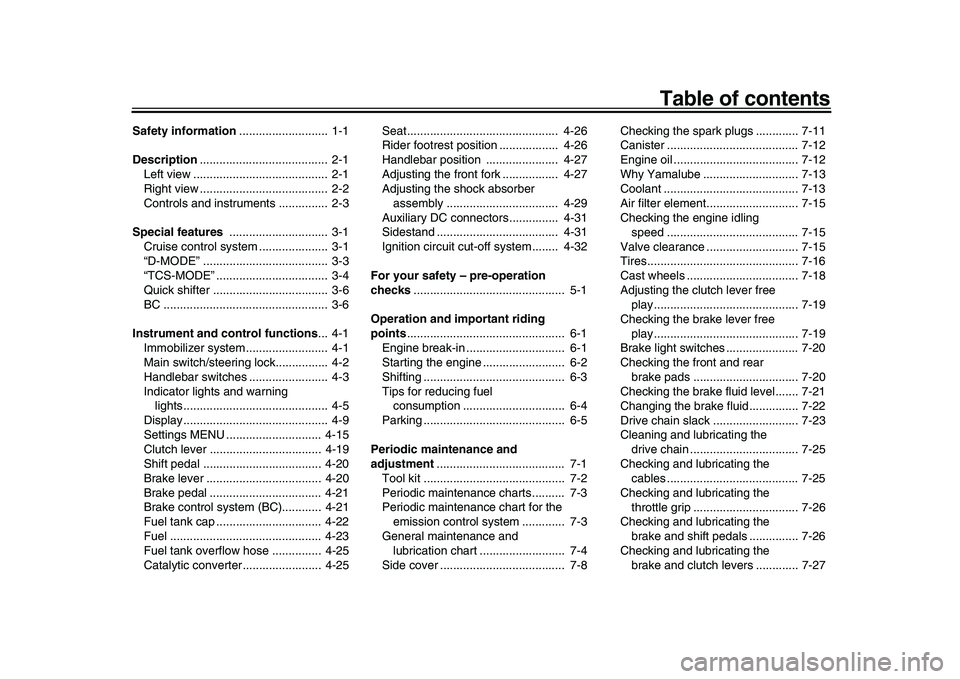
Table of contents
Safety information........................... 1-1
Description ....................................... 2-1
Left view ......................................... 2-1
Right view ....................................... 2-2
Controls and instruments ............... 2-3
Special features .............................. 3-1
Cruise control system .. ................... 3-1
“D-MODE” ...................................... 3-3
“TCS-MODE” .................................. 3-4
Quick shifter ................................... 3-6
BC .................................................. 3-6
Instrument and control functions ... 4-1
Immobilizer system ......................... 4-1
Main switch/steering lock................ 4-2
Handlebar switches .................... .... 4-3
Indicator lights and warning lights............................................ 4-5
Display............................................ 4-9
Settings MENU ............................. 4-15
Clutch lever .................................. 4-19
Shift pedal .................................... 4-20
Brake lever ................................... 4-20
Brake pedal ............... ................... 4-21
Brake control system (BC)............ 4-21
Fuel tank cap ................................ 4-22
Fuel .............................................. 4-23
Fuel tank overflow hose ............... 4-25
Catalytic converter........................ 4-25 Seat.............................................. 4-26
Rider footrest position .................. 4-26
Handlebar position ....
.................. 4-27
Adjusting the front fork ................. 4-27
Adjusting the shock absorber
assembly .................................. 4-29
Auxiliary DC connectors............... 4-31
Sidestand ..................................... 4-31
Ignition circuit cut-off system........ 4-32
For your safety – pre-operation
checks .............................................. 5-1
Operation and important riding
points ................................................ 6-1
Engine break-in .............................. 6-1
Starting the engine ......................... 6-2
Shifting ........................................... 6-3
Tips for reducing fuel consumption ............................... 6-4
Parking ........................................... 6-5
Periodic maintenance and
adjustment ....................................... 7-1
Tool kit ........................................... 7-2
Periodic maintenance charts.......... 7-3
Periodic maintenance chart for the emission control syst em ............. 7-3
General maintenance and lubrication chart .......................... 7-4
Side cover ...................................... 7-8 Checking the spark plugs ............. 7-11
Canister ........................................ 7-12
Engine oil ...................................... 7-12
Why Yamalube ............................. 7-13
Coolant ......................................... 7-13
Air filter element............................ 7-15
Checking the engine idling
speed ........................................ 7-15
Valve clearance ............................ 7-15
Tires.............................................. 7-16
Cast wheels .................................. 7-18
Adjusting the clutch lever free play............................................ 7-19
Checking the brake lever free
play............................................ 7-19
Brake light switches ...................... 7-20
Checking the front and rear
brake pads ................................ 7-20
Checking the brake fluid level....... 7-21
Changing the brake fluid............... 7-22
Drive chain slack .......................... 7-23
Cleaning and lubricating the drive chain ................................. 7-25
Checking and lubricating the cables ........................................ 7-25
Checking and lubricating the throttle grip ................................ 7-26
Checking and lubricating the
brake and shift pedals ............... 7-26
Checking and lubricating the brake and clutch levers ............. 7-27
BEA-28199-E0.book 1 ページ 2021年12月1日 水曜日 午後7時8分
Page 8 of 114
Table of contentsChecking and lubricating the sidestand ................................... 7-27
Lubricating the swingarm pivots ... 7-28
Checking the front fork ................. 7-28
Checking the steering ................... 7-29
Checking the wheel bearings ....... 7-29
Battery .......................................... 7-29
Replacing the fuses ...................... 7-32
Vehicle lights ................................ 7-34
License plate light ......................... 7-34
Supporting the moto rcycle ............ 7-34
Troubleshooting .......... .................. 7-35
Troubleshooting chart ................... 7-36
Motorcycle care and storage .......... 8-1
Matte color caution ......................... 8-1
Care ................................................ 8-1
Storage ........................................... 8-3
Specifications ................................... 9-1
Consumer information .................. 10-1
Identification numbers .................. 10-1
Diagnostic connector . ................... 10-2
Vehicle data recording .................. 10-2
Index ................................................ 11-1
BEA-28199-E0.book 2 ページ 2021年12月1日 水曜日 午後7時8分
Page 26 of 114
Instrument and control functions
4-3
1
2
34
5
6
7
8
9
10
11
12
13 To unlock the steering
Push the key in and turn it to “OFF”.
EAU66057
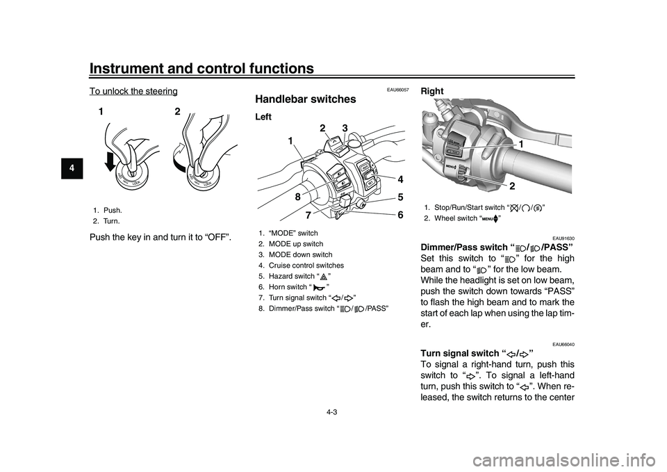
Handlebar switchesLeft
Right
EAU91630
Dimmer/Pass switch “ / /PASS”
Set this switch to “ ” for the high
beam and to “ ” for the low beam.
While the headlight is set on low beam,
push the switch down towards “PASS”
to flash the high beam and to mark the
start of each lap when using the lap tim-
er.
EAU66040
Turn signal switch “ / ”
To signal a right-hand turn, push this
switch to “ ”. To signal a left-hand
turn, push this switch to “ ”. When re-
leased, the switch returns to the center
1. Push.
2. Turn.12
1. “MODE” switch
2. MODE up switch
3. MODE down switch
4. Cruise control switches
5. Hazard switch “ ”
6. Horn switch “ ”
7. Turn signal switch “ / ”
8. Dimmer/Pass switch “ / /PASS”
RESSET
MODE
P
ASS
23
4
5
6
1
8 7
1. Stop/Run/Start switch “ / / ”
2. Wheel switch “ ”
1 1 12 2
BEA-28199-E0.book 3 ページ 2021年12月1日 水曜日 午後7時8分
Page 92 of 114
Periodic maintenance and adjustment
7-29
1
2
3
4
5
67
8
9
10
11
12
13
EAU23285
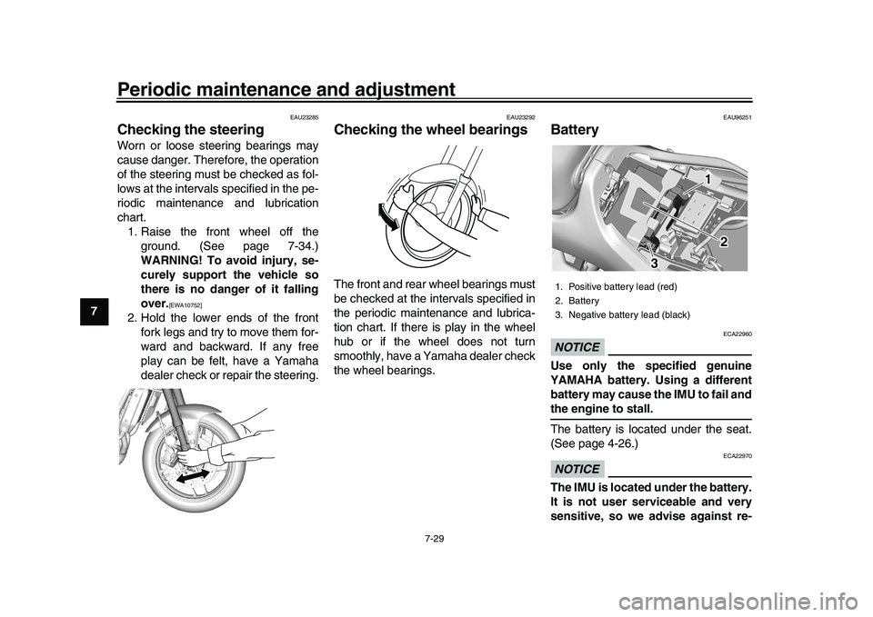
Checking the steeringWorn or loose steering bearings may
cause danger. Therefore, the operation
of the steering must be checked as fol-
lows at the intervals specified in the pe-
riodic maintenance and lubrication
chart. 1. Raise the front wheel off the ground. (See page 7-34.)
WARNING! To avoid injury, se-
curely support the vehicle so
there is no danger of it falling
over.
[EWA10752]
2. Hold the lower ends of the frontfork legs and try to move them for-
ward and backward. If any free
play can be felt, have a Yamaha
dealer check or repair the steering.
EAU23292
Checking the w heel bearingsThe front and rear wheel bearings must
be checked at the intervals specified in
the periodic maintenance and lubrica-
tion chart. If there is play in the wheel
hub or if the wheel does not turn
smoothly, have a Yamaha dealer check
the wheel bearings.
EAU96251
BatteryNOTICE
ECA22960
Use only the specified genuine
YAMAHA battery. Using a different
battery may cause the IMU to fail andthe engine to stall.
The battery is located under the seat.
(See page 4-26.)NOTICE
ECA22970
The IMU is located under the battery.
It is not user serviceable and very
sensitive, so we advise against re-1. Positive battery lead (red)
2. Battery
3. Negative battery lead (black)
1 1 1
2 2
3 3
BEA-28199-E0.book 29 ページ 2021年12月1日 水曜日 午後7時8分
Page 111 of 114
Index
11-2
1
2
3
4
5
6
7
8
9
101112
13
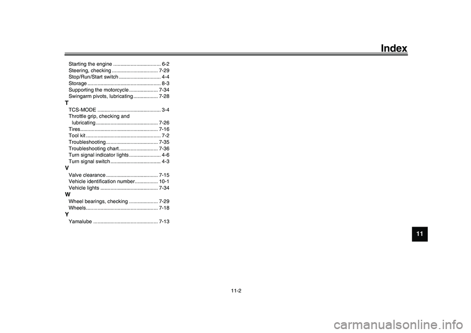
Starting the engine ................................. 6-2
Steering, checking ................................ 7-29
Stop/Run/Start switch ............................. 4-4
Storage ................................................... 8-3
Supporting the motorcycle .................... 7-34
Swingarm pivots, lubricating ................. 7-28TTCS-MODE ............................................ 3-4
Throttle grip, checking and lubricating ........................................... 7-26
Tires...................................................... 7-16
Tool kit .................................................... 7-2
Troubleshooting .................................... 7-35
Troubleshooting chart ........................... 7-36
Turn signal indicator lights ...................... 4-6
Turn signal switch ................................... 4-3VValve clearance .................................... 7-15
Vehicle identification number................ 10-1
Vehicle lights ........................................ 7-34WWheel bearings, c hecking .................... 7-29
Wheels.................................................. 7-18YYamalube ............................................. 7-13
BEA-28199-E0.book 2 ページ 2021年12月1日 水曜日 午後7時8分