YAMAHA YZ426F 2000 Betriebsanleitungen (in German)
Manufacturer: YAMAHA, Model Year: 2000, Model line: YZ426F, Model: YAMAHA YZ426F 2000Pages: 608, PDF-Größe: 45.52 MB
Page 451 of 608
5 - 19
CHAS
FREIN AVANT ET FREIN ARRIERE
VORDER- UND HINTERRADBREMSE
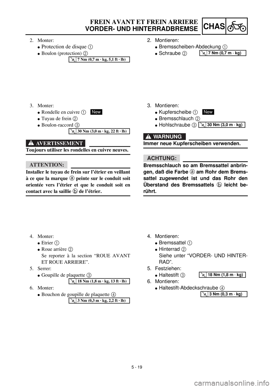
2. Montieren:
lBremsscheiben-Abdeckung 1
lSchraube 2 T R..7 Nm (0,7 m · kg)
3. Montieren:
lKupferscheibe 1
lBremsschlauch 2
lHohlschraube 3
WARNUNG
Immer neue Kupferscheiben verwenden.
ACHTUNG:
Bremsschlauch so am Bremssattel anbrin-
gen, daß die Farbe a am Rohr dem Brems-
sattel zugewendet ist und das Rohr den
Überstand des Bremssattels b leicht be-
rührt.
New
T R..30 Nm (3,0 m · kg)
4. Montieren:
lBremssattel 1
lHinterrad 2
Siehe unter “VORDER- UND HINTER-
RAD”.
5. Festziehen:
lHaltestift 3
6. Montieren:
lHaltestift-Abdeckschraube 4
T R..18 Nm (1,8 m · kg)
T R..3 Nm (0,3 m · kg)
2. Monter:
lProtection de disque 1
lBoulon (protection) 2
T R..7 Nm (0,7 m · kg, 5,1 ft · lb)
3. Monter:
lRondelle en cuivre 1
lTuyau de frein 2
lBoulon-raccord 3
AVERTISSEMENT
Toujours utiliser les rondelles en cuivre neuves.
ATTENTION:
Installer le tuyau de frein sur l’étrier en veillant
à ce que la marque a peinte sur le conduit soit
orientée vers l’étrier et que le conduit soit en
contact avec la saillie b de l’étrier.
New
T R..30 Nm (3,0 m · kg, 22 ft · lb)
4. Monter:
lEtrier 1
lRoue arrière 2
Se reporter à la section “ROUE AVANT
ET ROUE ARRIERE”.
5. Serrer:
lGoupille de plaquette 3
6. Monter:
lBouchon de goupille de plaquette 4
T R..18 Nm (1,8 m · kg, 13 ft · lb)
T R..3 Nm (0,3 m · kg, 2,2 ft · lb)
Page 452 of 608
5 - 20
CHASFRONT BRAKE AND REAR BRAKE
EC5A5200
Master cylinder kit
1. Clean:
lMaster cylinder
lMaster cylinder kit
Clean them with brake fluid.
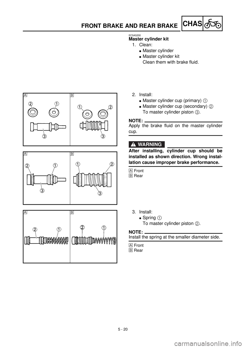
2. Install:
lMaster cylinder cup (primary) 1
lMaster cylinder cup (secondary) 2
To master cylinder piston 3.
NOTE:
Apply the brake fluid on the master cylinder
cup.
WARNING
After installing, cylinder cup should be
installed as shown direction. Wrong instal-
lation cause improper brake performance.
Front
õRear
õ
õ
3. Install:
lSpring 1
To master cylinder piston 2.
NOTE:
Install the spring at the smaller diameter side.
Front
õRear
õ
Page 453 of 608
5 - 20
CHAS
FREIN AVANT ET FREIN ARRIERE
VORDER- UND HINTERRADBREMSE
Hauptbremszylinder-Bauteile
1. Reinigen:
lHauptbremszylinder
lHauptbremszylinder-Bauteile
Mit Bremsflüssigkeit reinigen.
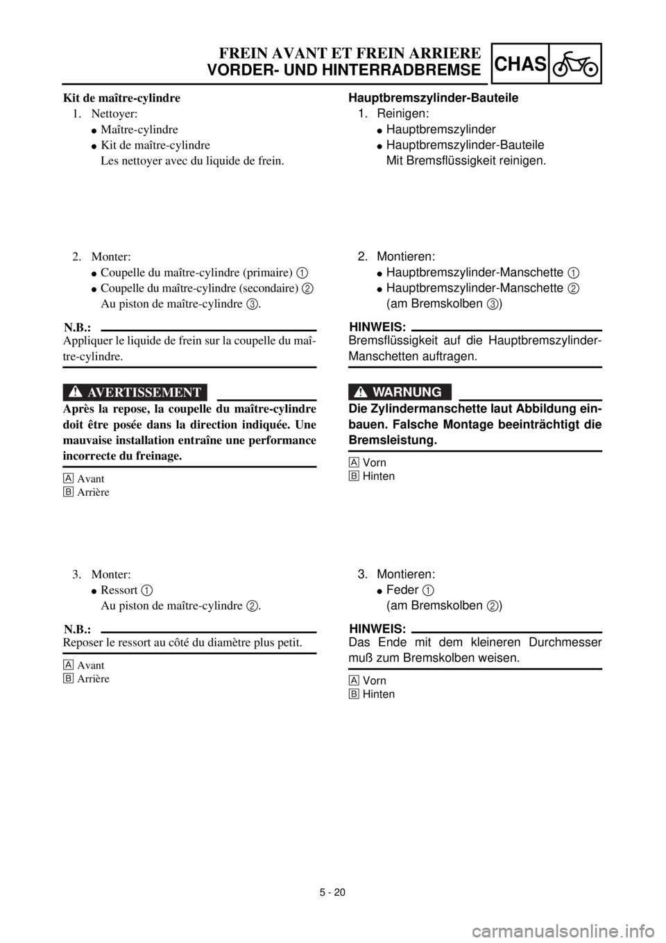
2. Montieren:
lHauptbremszylinder-Manschette 1
lHauptbremszylinder-Manschette 2
(am Bremskolben 3)
HINWEIS:
Bremsflüssigkeit auf die Hauptbremszylinder-
Manschetten auftragen.
WARNUNG
Die Zylindermanschette laut Abbildung ein-
bauen. Falsche Montage beeinträchtigt die
Bremsleistung.
Vorn
õHinten
3. Montieren:
lFeder 1
(am Bremskolben 2)
HINWEIS:
Das Ende mit dem kleineren Durchmesser
muß zum Bremskolben weisen.
Vorn
õHinten
Kit de maître-cylindre
1. Nettoyer:
lMaître-cylindre
lKit de maître-cylindre
Les nettoyer avec du liquide de frein.
2. Monter:
lCoupelle du maître-cylindre (primaire) 1
lCoupelle du maître-cylindre (secondaire) 2
Au piston de maître-cylindre 3.
N.B.:
Appliquer le liquide de frein sur la coupelle du maî-
tre-cylindre.
AVERTISSEMENT
Après la repose, la coupelle du maître-cylindre
doit être posée dans la direction indiquée. Une
mauvaise installation entraîne une performance
incorrecte du freinage.
Avant
õArrière
3. Monter:
lRessort 1
Au piston de maître-cylindre 2.
N.B.:
Reposer le ressort au côté du diamètre plus petit.
Avant
õArrière
Page 454 of 608
![YAMAHA YZ426F 2000 Betriebsanleitungen (in German)
5 - 21
CHAS
FRONT BRAKE AND REAR BRAKE
4. Install:
[Front]
l
Master cylinder kit
1
l
Push rod
2
l
Plain washer
3
l
Circlip
4
l
Master cylinder boot
5
YAMAHA YZ426F 2000 Betriebsanleitungen (in German)
5 - 21
CHAS
FRONT BRAKE AND REAR BRAKE
4. Install:
[Front]
l
Master cylinder kit
1
l
Push rod
2
l
Plain washer
3
l
Circlip
4
l
Master cylinder boot
5](/img/51/53972/w960_53972-453.png)
5 - 21
CHAS
FRONT BRAKE AND REAR BRAKE
4. Install:
[Front]
l
Master cylinder kit
1
l
Push rod
2
l
Plain washer
3
l
Circlip
4
l
Master cylinder boot
5
l
Locknut
6
To master cylinder
7
.
[Rear]
l
Master cylinder kit
1
l
Push rod
2
l
Circlip
3
l
Master cylinder boot
4
l
Locknut
5
To master cylinder
6
.
NOTE:
l
Apply the brake fluid on the master cylinder
kit.
l
Apply the lithium soap base grease on the tip
of the push rod.
l
When installing the circlip, use a long nose
circlip pliers.
Front
õ
Rear
EC5A5300
Front master cylinder
1. Install:
l
Master cylinder
1
l
Master cylinder bracket
2
l
Bolt (master cylinder bracket)
3
NOTE:
l
Install the bracket so that the arrow mark
a
face upward.
l
First tighten the bolts on the upper side of the
master cylinder bracket, and then tighten the
bolts on the lower side.
WARNING
Install the master cylinder so that the gaps
b
and
c
between the bolt (grip cap)
4
and
push rod
5
are equal. If you make a mis-
take in the master cylinder installation
position, the brake lever may contact the
grip cap, resulting in poor brake perfor-
mance.
õ
T R..9 Nm (0.9 m · kg, 6.5 ft · lb)
Page 455 of 608
![YAMAHA YZ426F 2000 Betriebsanleitungen (in German)
5 - 21
CHAS
FREIN AVANT ET FREIN ARRIERE
VORDER- UND HINTERRADBREMSE
4. Montieren:
[Vorn]
l
Hauptbremszylinder-Bauteile
1
l
Druckstange
2
l
Beilagscheibe
3
l
Sicher YAMAHA YZ426F 2000 Betriebsanleitungen (in German)
5 - 21
CHAS
FREIN AVANT ET FREIN ARRIERE
VORDER- UND HINTERRADBREMSE
4. Montieren:
[Vorn]
l
Hauptbremszylinder-Bauteile
1
l
Druckstange
2
l
Beilagscheibe
3
l
Sicher](/img/51/53972/w960_53972-454.png)
5 - 21
CHAS
FREIN AVANT ET FREIN ARRIERE
VORDER- UND HINTERRADBREMSE
4. Montieren:
[Vorn]
l
Hauptbremszylinder-Bauteile
1
l
Druckstange
2
l
Beilagscheibe
3
l
Sicherungsring
4
l
Staubschutzkappe
5
l
Sicherungsmutter
6
(am Hauptbremszylinder
7
)
[Hinten]
l
Hauptbremszylinder-Bauteile
1
l
Druckstange
2
l
Sicherungsring
3
l
Staubschutzkappe
4
l
Sicherungsmutter
5
(am Hauptbremszylinder
6
)
HINWEIS:
l
Bremsflüssigkeit auf die Hauptbremszylin-
der-Bauteile auftragen.
l
Lithiumfett am Druckstangen-Ende auftra-
gen.
l
Den Sicherungsring mit einer Spitzzange
montieren.
Vorn
õ
Hinten
Hauptbremszylinder vorn
1. Montieren:
l
Hauptbremszylinder
1
l
Halterung
2
l
Schraube (Halterung)
3
HINWEIS:
l
Die Halterung so einbauen, daß die Pfeil-
markierung
a
nach oben weist.
l
Zuerst die oberen, dann die unteren Schrau-
ben der Hauptbremszylinder-Halterung fest-
ziehen.
WARNUNG
Den Hauptbremszylinder so einbauen, daß
die Spalte
b
und
c
zwischen der Seilzug-
gehäuse-Schraube
4
und der Druckstan-
ge
5
gleich groß sind. Falsche Montage
beeinträchtigt die Bremsleistung.
T R..9 Nm (0,9 m · kg)
4. Monter:
[Avant]
l
Kit de maître-cylindre
1
l
Tige de commande
2
l
Rondelle ordinaire
3
l
Circlip
4
l
Soufflet de maître-cylindre
5
l
Contre-écrou
6
Sur le maître-cylindre
7
.
[Arrière]
l
Kit de maître-cylindre
1
l
Tige de commande
2
l
Circlip
3
lSoufflet de maître-cylindre 4
lContre-écrou 5
Sur le maître-cylindre 6.
N.B.:
lAppliquer le liquide de frein sur l’ensemble du
maître-cylindre.
lAppliquer de la graisse au lithium sur l’extrémité
de la tige de commande.
lPour mettre le circlip en place, utiliser un pinces
de circlip à longs becs.
Avant
õArrière
Maître-cylindre avant
1. Monter:
lMaître-cylindre 1
lDemi-palier de fixation de maître-cylindre 2
lBoulon (demi-palier de fixation) 3
N.B.:
lReposer le support pour que la flèche a soit diri-
gée vers le haut.
lSerrer d’abord les boulons sur le côté supérieur
du demi-palier de fixation de maître-cylindre, puis
serrer les boulons sur le côté inférieur.
AVERTISSEMENT
Installer le maître-cylindre de sorte que les espa-
ces b et c entre le boulon (capuchon de poi-
gnée) 4 et la tige de commande 5 soient
identiques. Si le maître-cylindre est mal posi-
tionné, le levier de frein risque de toucher le
capuchon de poignée et la puissance de freinage
sera réduite.
T R..9 Nm (0,9 m · kg, 6,5 ft · lb)
Page 456 of 608
5 - 22
CHAS
FRONT BRAKE AND REAR BRAKE
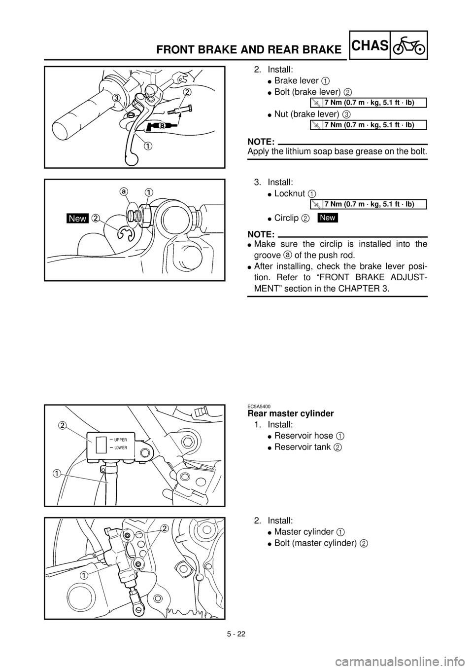
2. Install:
l
Brake lever
1
l
Bolt (brake lever)
2
l
Nut (brake lever)
3
NOTE:
Apply the lithium soap base grease on the bolt.
T R..7 Nm (0.7 m · kg, 5.1 ft · lb)
T R..7 Nm (0.7 m · kg, 5.1 ft · lb)
3. Install:
l
Locknut
1
l
Circlip
2
NOTE:
l
Make sure the circlip is installed into the
groove
a
of the push rod.
l
After installing, check the brake lever posi-
tion. Refer to “FRONT BRAKE ADJUST-
MENT” section in the CHAPTER 3.
T R..7 Nm (0.7 m · kg, 5.1 ft · lb)
New
EC5A5400
Rear master cylinder
1. Install:
lReservoir hose 1
lReservoir tank 2
2. Install:
lMaster cylinder 1
lBolt (master cylinder) 2
Page 457 of 608
5 - 22
CHAS
FREIN AVANT ET FREIN ARRIERE
VORDER- UND HINTERRADBREMSE
2. Montieren:
lBremshebel 1
lSchraube (Bremshebel) 2
lMutter (Bremshebel) 3
HINWEIS:
Lithiumfett auf die Schraube auftragen.
T R..7 Nm (0,7 m · kg)
T R..7 Nm (0,7 m · kg)
3. Montieren:
lSicherungsmutter 1
lSicherungsring 2
HINWEIS:
lDer Sicherungsring muß in der Nut a der
Druckstange sitzen.
lNach der Montage die Handbremshebelposi-
tion überprüfen. Siehe unter “EVORDER-
RADBREMSE EINSTELLEN” im KAPITEL 3.
T R..7 Nm (0,7 m · kg)
New
Hauptbremszylinder hinten
1. Montieren:
lBehälterschlauch 1
lBremsflüssigkeitsbehälter 2
2. Montieren:
lHauptbremszylinder 1
lSchrauben (Hauptbremszylinder) 2 2. Monter:
lLevier de frein 1
lBoulon (levier de frein) 2
lEcrou (levier de frein) 3
N.B.:
Appliquer de la graisse à base de savon au lithium
sur le boulon.
T R..7 Nm (0,7 m · kg, 5,1 ft · lb)
T R..7 Nm (0,7 m · kg, 5,1 ft · lb)
3. Monter:
lContre-écrou 1
lCirclip 2
N.B.:
lS’assurer que le circlip est installé dans la rainure
a de la tige de commande.
lUne fois l’installation terminée, contrôler la posi-
tion du levier de frein.
Se reporter à la section “REGLAGE DE FREIN
AVANT” du CHAPITRE 3.
T R..7 Nm (0,7 m · kg, 5,1 ft · lb)
New
Maître-cylindre arrière
1. Monter:
lTuyau de réservoir 1
lRéservoir de réserve 2
2. Monter:
lMaître-cylindre 1
lBoulon (maître-cylindre) 2
Page 458 of 608
5 - 23
CHASFRONT BRAKE AND REAR BRAKE
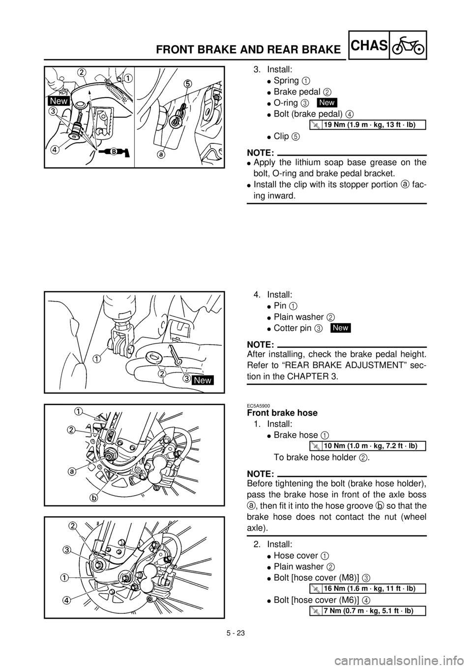
3. Install:
lSpring 1
lBrake pedal 2
lO-ring 3
lBolt (brake pedal) 4
lClip 5
NOTE:
lApply the lithium soap base grease on the
bolt, O-ring and brake pedal bracket.
lInstall the clip with its stopper portion a fac-
ing inward.
New
T R..19 Nm (1.9 m · kg, 13 ft · lb)
4. Install:
lPin 1
lPlain washer 2
lCotter pin 3
NOTE:
After installing, check the brake pedal height.
Refer to “REAR BRAKE ADJUSTMENT” sec-
tion in the CHAPTER 3.
New
EC5A5900
Front brake hose
1. Install:
lBrake hose 1
To brake hose holder 2.
NOTE:
Before tightening the bolt (brake hose holder),
pass the brake hose in front of the axle boss
a, then fit it into the hose groove b so that the
brake hose does not contact the nut (wheel
axle).
2. Install:
lHose cover 1
lPlain washer 2
lBolt [hose cover (M8)] 3
lBolt [hose cover (M6)] 4
T R..10 Nm (1.0 m · kg, 7.2 ft · lb)
T R..16 Nm (1.6 m · kg, 11 ft · lb)
T R..7 Nm (0.7 m · kg, 5.1 ft · lb)
Page 459 of 608
5 - 23
CHAS
FREIN AVANT ET FREIN ARRIERE
VORDER- UND HINTERRADBREMSE
3. Montieren:
lFeder 1
lFußbremshebel 2
lO-Ring 3
lSchraube (Fußbremshebel) 4
lSchlauchschelle 5
HINWEIS:
lLithiumfett auf Schraube, O-Ring und Fuß-
bremshebel-Halterung auftragen.
lDen Clip so einbauen, daß das Ende a
nach innen weist.
New
T R..19 Nm (1,9 m · kg)
3. Monter:
lRessort 1
lPédale de frein 2
lJoint torique 3
lBoulon (pédale de frein) 4
lAgrafe 5
N.B.:
lAppliquer de la graisse à base de savon au
lithium sur le boulon, le joint torique et le support
de pédale de frein.
lMettre le collier de fixation, côté butée a tourné
vers l’intérieur.
New
T R..19 Nm (1,9 m · kg, 13 ft · lb)
4. Montieren:
lStift 1
lBeilagscheibe 2
lSplint 3
HINWEIS:
Nach der Montage die Fußbremshebelposition
kontrollieren.
Siehe unter “HINTERRADBREMSE EINSTEL-
LEN” im KAPITEL 3.
New
Bremsschlauch vorn
1. Montieren:
lBremsschlauch 1
(mit der Halterung 2)
HINWEIS:
Vor dem Festziehen dieser Schraube (Halte-
rung) den Bremsschlauch am Gabelbein-Vor-
sprung a vorbei und durch die Nut b führen,
so daß dieser die Achsmutter nicht berührt.
2. Montieren:
lSchlauchabdeckung 1
lBeilagscheibe 2
lM8-Schraube (Schlauchabdeckung) 3
lM6-Schraube (Schlauchabdeckung) 4
T R..10 Nm (1,0 m · kg)
T R..16 Nm (1,6 m · kg)
T R..7 Nm (0,7 m · kg)
4. Monter:
lGoupille 1
lRondelle ordinaire 2
lGoupille fendue 3
N.B.:
Après de montage, contrôler la hauteur de pédale
de frein.
Se reporter à la section “REGLAGE DU FREIN
ARRIERE” du CHAPITRE 3.
New
Tuyau de frein avant
1. Monter:
lTuyau de frein 1
Sur le support de tuyau de frein 2.
N.B.:
Avant de serrer le boulon (support de tuyau de
frein), faire passer le tuyau de frein à l’avant du
bossage d’essieu a, puis l’insérer dans la canne-
lure de tuyau b pour que le tuyau de frein ne tou-
che pas l’écrou (axe de roue).
2. Monter:
lCache de tuyau 1
lRondelle ordinaire 2
lBoulon [cache de tuyau (M8)] 3
lBoulon [cache de tuyau (M6)] 4
T R..10 Nm (1,0 m · kg, 7,2 ft · lb)
T R..16 Nm (1,6 m · kg, 11 ft · lb)
T R..7 Nm (0,7 m · kg, 5,1 ft · lb)
Page 460 of 608
5 - 24
CHASFRONT BRAKE AND REAR BRAKE
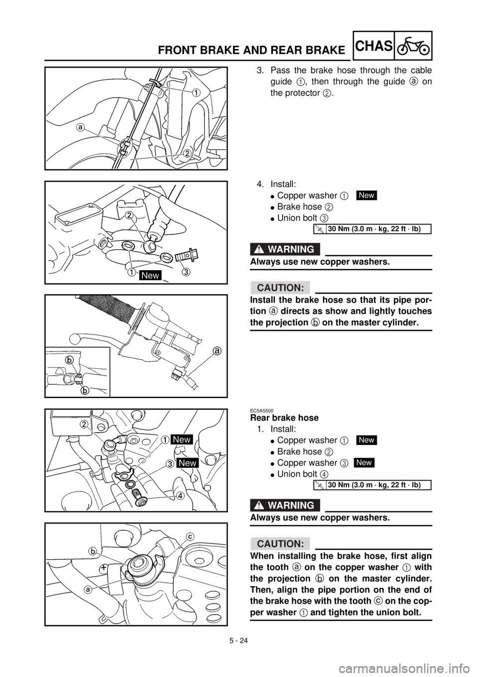
3. Pass the brake hose through the cable
guide 1, then through the guide a on
the protector 2.
4. Install:
lCopper washer 1
lBrake hose 2
lUnion bolt 3
WARNING
Always use new copper washers.
ACHTUNG:CAUTION:
Install the brake hose so that its pipe por-
tion a directs as show and lightly touches
the projection b on the master cylinder.
New
T R..30 Nm (3.0 m · kg, 22 ft · lb)
EC5A5500
Rear brake hose
1. Install:
lCopper washer 1
lBrake hose 2
lCopper washer 3
lUnion bolt 4
WARNING
Always use new copper washers.
ACHTUNG:CAUTION:
When installing the brake hose, first align
the tooth a on the copper washer 1 with
the projection b on the master cylinder.
Then, align the pipe portion on the end of
the brake hose with the tooth c on the cop-
per washer 1 and tighten the union bolt.
New
New
T R..30 Nm (3.0 m · kg, 22 ft · lb)