YAMAHA YZ450F 2005 Notices Demploi (in French)
Manufacturer: YAMAHA, Model Year: 2005, Model line: YZ450F, Model: YAMAHA YZ450F 2005Pages: 646, PDF Size: 16.06 MB
Page 591 of 646

–+ELEC
HANDHABUNGSHINWEISE
ACHTUNG:
Die Drosselklappensensor-Schrauben 1
dürfen nicht gelockert werden, außer wenn
der Drosselklappensensor zu erneuern ist.
STECKVERBINDER- UND
KABELANSCHLÜSSE KONTROLLIEREN
1. Kontrollieren:
Steckverbinder- und Kabelanschlüsse
Rostig/staubig/locker/kurzgeschlossen →
Instand setzen, ggf. erneuern.
DROSSELKLAPPENSENSOR-SPULE
KONTROLLIEREN
1. Kontrollieren:
Drosselklappensensor-Spule
Nicht nach Vorgabe → Erneuern.
2. Lockern:
Leerlaufeinstellschraube 1
HINWEIS:
Die Leerlaufeinstellschraube herausdrehen,
bis die Drosselklappenwelle sich in der völlig
geschlossenen Stellung befindet.Meßkabel (+)→ Blau 1
Meßkabel (–) → Schwarz 2
Drosselklappen-
sensor-Spulenwi-
derstandMeßgerät-
Wahlschalter
4–6 kΩ bei
20 °C (68 °F)kΩ × 1
SYSTEME TPS (CAPTEUR DE POSITION DE PAPILLON DES GAZ)
DROSSELKLAPPENSENSOR
REMARQUES CONCERNANT LA
MANIPULATION
ATTENTION:
Ne pas desserrer les vis {TPS (capteur de position
de papillon des gaz)} 1 sauf en cas de remplace-
ment du TPS (capteur de position de papillon des
gaz) en raison d’une panne, car cela provoquerait
une baisse des performances du moteur.
CONTROLE DES CONNEXIONS DES
FICHES RAPIDES ET DES FILS
1. Contrôler:
Connexion des fiches rapides et des fils
Rouille/poussière/jeu/court-circuit → Répa-
rer ou remplacer.
CONTROLE DE LA BOBINE DU TPS
1. Contrôler:
Résistance de la bobine du TPS
Hors spécifications → Remplacer.
2. Desserrer:
Vis de butée de papillon des gaz 1
N.B.:
Dévisser la vis de butée de papillon des gaz jusqu’à
ce que l’axe de papillon soit en position complète-
ment fermée. Fil (+) du multimètre → fil bleu 1
Fil (–) du multimètre → fil noir 2
Résistance de la
bobine du TPSPosition du sélec-
teur du multimètre
4 à 6 kΩ à
20 °C (68 °F)kΩ × 1
6 - 8
Page 592 of 646

6 - 9
–+ELECTPS (THROTTLE POSITION SENSOR) SYSTEM
3. Inspect:
TPS coil variable resistance
Check that the resistance in increased as
the throttle grip is moved from the full
close position to the full open position.
Out of specification → Replace.
Tester (+) lead
→ Yellow lead
1
Tester (–) lead
→ Black lead
2
TPS coil variable
resistanceTester selec-
tor position
Full closed Full opened
k
Ω
× 1 0 ~ 2 k
Ω
at 20 °C
(68°F)4 ~ 6 k
Ω
at 20 °C
(68°F)
TPS REPLACEMENT AND ADJUSTMENT
1. Remove:
TPS coupler
Screw (TPS) 1
TPS 2
NOTE:
Loosen the screws (TPS) using the T25 bit.
2. Replace:
TPS
3. Install:
TPS 1
Screw (TPS) 2
TPS coupler
NOTE:
Align the slot a in the TPS with the projec-
tion b on the carburetor.
Temporarily tighten the screws (TPS).
12
21
b
a
Page 593 of 646

–+ELEC
3. Kontrollieren:
Drosselklappensensor-Widerstand
Darauf achten, daß der Widerstand all-
mählich ansteigt, während der Gasdreh-
griff geöffnet wird.
Nicht nach Vorgabe → Erneuern.
Meßkabel (+) → Gelb 1
Meßkabel (–) → Schwarz 2
Drosselklappensen-
sor-WiderstandMeßgerät-
Wahlschal-
ter
Ganz
geschlossenGanz
geöffnet
kΩ × 1
0–2 kΩ
bei 20 °C
(68°F)4–6 kΩ
bei 20 °C
(68°F)
DROSSELKLAPPENSENSOR ERNEUERN
UND EINSTELLEN
1. Demontieren:
Drosselklappensensor-Steckverbinder
Schraube (Drosselklappensensor) 1
Drosselklappensensor 2
HINWEIS:
Die Drosselklappensensor-Schrauben mit
einem T25-Einsatz lockern.
2. Erneuern:
Drosselklappensensor
3. Montieren:
Drosselklappensensor 1
Schraube (Drosselklappensensor) 2
Drosselklappensensor-Steckverbinder
HINWEIS:
Die Haltenase b am Vergaser muß in der
Nut a im Drosselklappensensor sitzen.
Die Drosselklappensensor-Schrauben provi-
sorisch festziehen. SYSTEME TPS (CAPTEUR DE POSITION DE PAPILLON DES GAZ)
DROSSELKLAPPENSENSOR
3. Contrôler:
Résistance variable de la bobine du TPS
Vérifier que la résistance augmente lorsque
l’on déplace la poignée des gaz de la position
complètement fermée à la position complète-
ment ouverte.
Hors spécifications → Remplacer.
Fil (+) du multimètre → fil jaune 1
Fil (–) du multimètre → fil noir 2
Résistance variable de la
bobine du TPSPosition du
sélecteur du
multimètre
Complète-
ment ferméComplète-
ment ouvert
kΩ × 1
0 à 2 kΩ à
20 °C
(68°F)4 à 6 kΩ à
20 °C
(68°F)
REMPLACEMENT ET REGLAGE DU TPS
1. Déposer:
Fiche rapide du TPS
Vis (TPS) 1
TPS 2
N.B.:
Desserrer les vis (TPS) à l’aide de la mèche T25.
2. Remplacer:
TPS
3. Monter:
TPS 1
Vis (TPS) 2
Fiche rapide du TPS
N.B.:
Aligner la fente a du TPS avec la saillie b du
carburateur.
Serrer provisoirement les vis (TPS).
6 - 9
Page 594 of 646

6 - 10
–+ELECTPS (THROTTLE POSITION SENSOR) SYSTEM
4. Adjust:
Idle speed
Refer to “IDLE SPEED ADJUSTMENT”
section in the CHAPTER 3.
5. Insert the thin electric conductors 2 (lead)
into the TPS coupler 1, as shown, and
connect the tester to them.
CAUTION:
Do not insert the electric conductors
more than required because it may
reduce the waterproof function of the
coupler.
Make sure that a short-circuit does not
develop between the terminals because it
may cause damage to electrical compo-
nents.
6. Start the engine.
7. Adjust:
TPS output voltage Tester (+) lead
→ Yellow lead
3
Tester (–) lead
→ Black lead
4
Adjustment steps:
Adjust the installation angle of the TPS 1 to
obtain the specified output voltage.
NOTE:
Measure the output voltage accurately with
a digital electronic voltmeter that gives an
easy reading of a small voltage.
TPS output
voltageTester selector
position
0.58 ~ 0.78 V DCV
Page 595 of 646

–+ELEC
4. Einstellen:
Leerlaufdrehzahl
Siehe unter “LEERLAUFDREHZAHL
EINSTELLEN” in KAPITEL 3.
5. Dünne Leiter (Kabel) 2, wie in der Abbil-
dung gezeigt, in den Drosselklappensen-
sor-Steckverbinder 1 stecken und das
Meßgerät daran anschließen.
ACHTUNG:
Die elektrischen Leiter nicht tiefer als not-
wendig in den Steckverbinder stecken,
um dessen Wasserdichtigkeit nicht zu
beeinträchtigen.
Darauf achten, daß kein Kurzschluß vor-
liegt, um eine Beschädigung der elektri-
schen Anlage zu vermeiden.
6. Den Motor starten.
7. Einstellen:
Drosselklappensensor-Ausgangsspan-
nung Meßkabel (+) → Gelb 3
Meßkabel (–) → Schwarz 4
Arbeitsvorgang:
Den Einbauwinkel des Drosselklappensen-
sors 1 so einstellen, daß die vorgeschrie-
bene Ausgangsspannung anliegt.
HINWEIS:
Die Ausgangsspannung muß mit einem prä-
zisen Digitalmeßgerät erfaßt werden.
Drosselklappen-
sensor-Ausgangs-
spannungMeßgerät-
Wahlschalter
0,58–0,78 V DCV
SYSTEME TPS (CAPTEUR DE POSITION DE PAPILLON DES GAZ)
DROSSELKLAPPENSENSOR
4. Régler:
Ralenti
Se reporter à la section “REGLAGE DU
REGIME DE RALENTI” au CHAPITRE 3.
5. Introduire les fins conducteurs électriques 2
(fil) dans la fiche rapide du TPS 1, comme
illustré, et y raccorder le multimètre.
ATTENTION:
Ne pas introduire les conducteurs électriques
plus que nécessaire parce que cela risque de
réduire l’étanchéité de la fiche rapide.
Veiller à ce qu’aucun court-circuit ne se pro-
duise entre les bornes car cela risque d’endom-
mager les composants électriques.
6. Mettre le moteur en marche.
7. Régler:
Tension de sortie du TPS Fil (+) du multimètre → fil jaune 3
Fil (–) du multimètre → fil noir 4
Étapes du réglage:
Régler l’angle de montage du TPS 1 de manière
à obtenir la tension de sortie spécifiée.
N.B.:
Mesurer avec précision la tension de sortie à
l’aide d’un voltmètre électronique permettant
une lecture facile des faibles tensions.
Tension de sortie
du TPSPosition du sélec-
teur du multimètre
0,58 à 0,78 V DCV
6 - 10
Page 596 of 646

6 - 11
–+ELECTPS (THROTTLE POSITION SENSOR) SYSTEM
8. Tighten:
Screw (TPS) 1
9. Stop the engine.
1
EC694000
TPS INPUT VOLTAGE INSPECTION
1. Disconnect the TPS coupler.
2. Start the engine.
3. Inspect:
TPS input voltage
Out of specification → Replace the CDI
unit.
Tester (+) lead
→ Blue lead
1
Tester (–) lead
→ Black/Blue lead
2
TPS input
voltageTester selector
position
4 ~ 6 V DCV-20
Page 597 of 646

–+ELEC
8. Festziehen:
Schraube (Drosselklappensensor) 1
9. Den Motor abstellen.
DROSSELKLAPPENSENSOR-
EINGANGSSPANNUNG KONTROLLIEREN
1. Den Drosselklappensensor-Steckverbin-
der abziehen.
2. Den Motor starten.
3. Kontrollieren:
Drosselklappensensor-Eingangsspan-
nung
Nicht nach Vorgabe → Zündbox erneu-
ern.
Meßkabel (+) → Blau 1
Meßkabel (–) → Schwarz/Blau 2
Drosselklappen-
sensor-Eingangs-
spannungMeßgerät-
Wahlschalter
4–6 V DCV-20
SYSTEME TPS (CAPTEUR DE POSITION DE PAPILLON DES GAZ)
DROSSELKLAPPENSENSOR
8. Serrer :
Vis (TPS) 1
9. Arrêter le moteur.
CONTROLE DE LA TENSION D’ENTREE
DU TPS
1. Débrancher la fiche rapide du TPS.
2. Mettre le moteur en marche.
3. Contrôler:
Tension d’entrée du TPS
Hors spécifications → Remplacer le boîtier
CDI.
Fil (+) du multimètre → fil bleu 1
Fil (–) du multimètre → fil noir/bleu 2
Tension d’entrée
du TPSPosition du sélec-
teur du multimètre
4 à 6 V DCV-20
6 - 11
Page 598 of 646

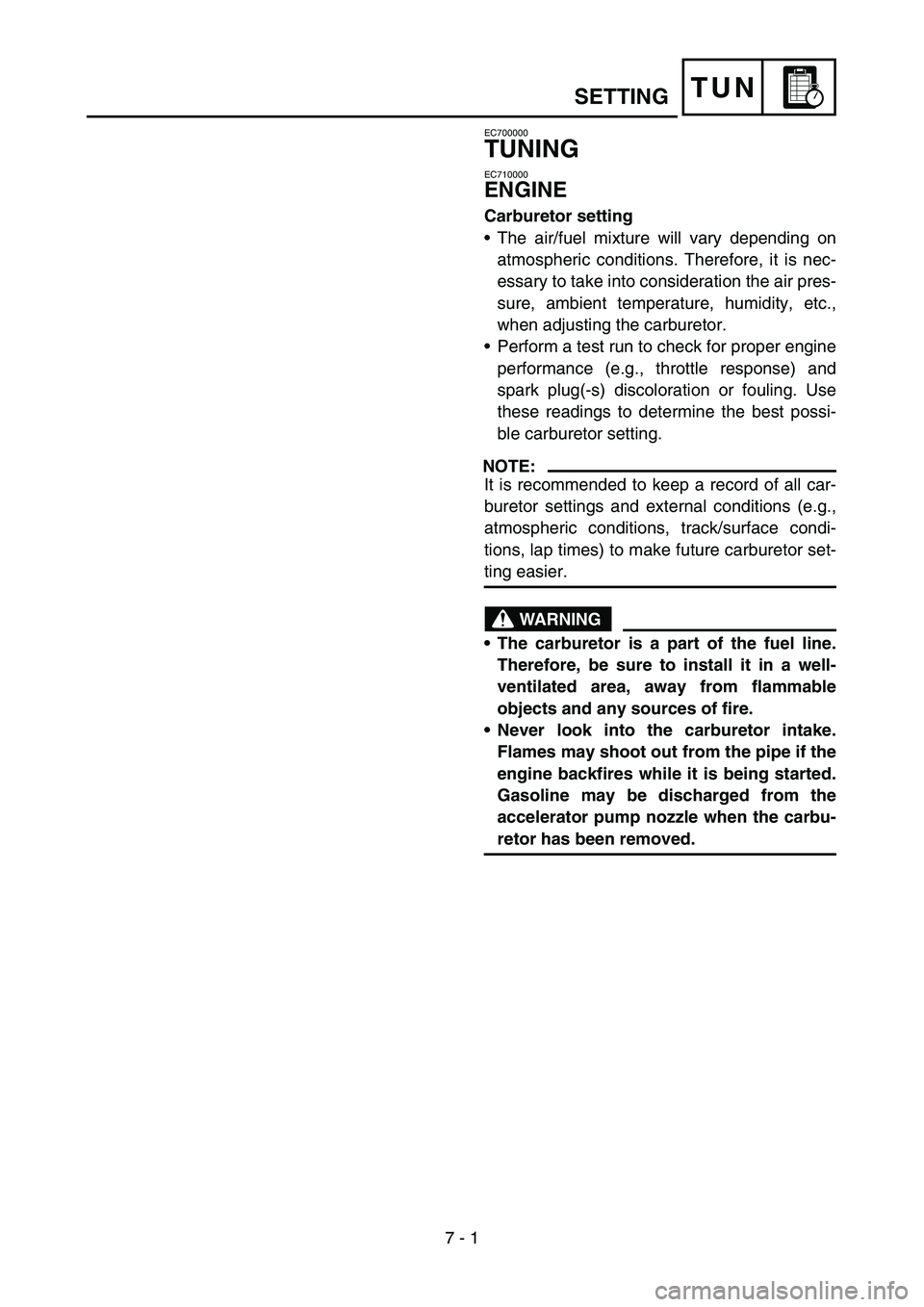
7 - 1
TUN
EC700000
TUNING
EC710000
ENGINE
Carburetor setting
The air/fuel mixture will vary depending on
atmospheric conditions. Therefore, it is nec-
essary to take into consideration the air pres-
sure, ambient temperature, humidity, etc.,
when adjusting the carburetor.
Perform a test run to check for proper engine
performance (e.g., throttle response) and
spark plug(-s) discoloration or fouling. Use
these readings to determine the best possi-
ble carburetor setting.
NOTE:
It is recommended to keep a record of all car-
buretor settings and external conditions (e.g.,
atmospheric conditions, track/surface condi-
tions, lap times) to make future carburetor set-
ting easier.
WARNING
The carburetor is a part of the fuel line.
Therefore, be sure to install it in a well-
ventilated area, away from flammable
objects and any sources of fire.
Never look into the carburetor intake.
Flames may shoot out from the pipe if the
engine backfires while it is being started.
Gasoline may be discharged from the
accelerator pump nozzle when the carbu-
retor has been removed.
SETTING
Page 599 of 646

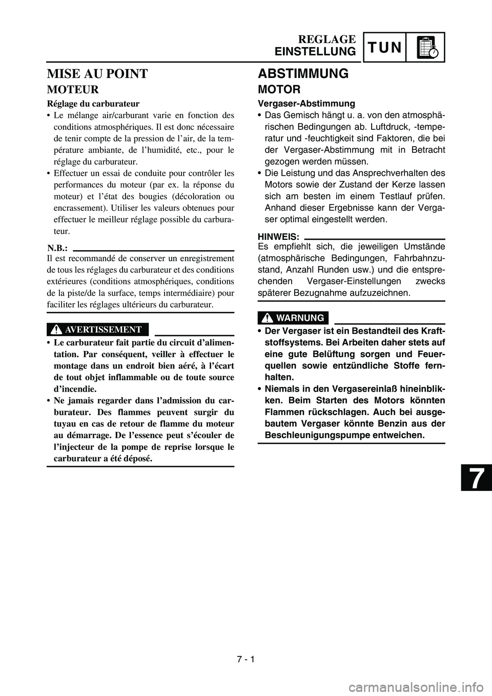
TUN
ABSTIMMUNG
MOTOR
Vergaser-Abstimmung
Das Gemisch hängt u. a. von den atmosphä-
rischen Bedingungen ab. Luftdruck, -tempe-
ratur und -feuchtigkeit sind Faktoren, die bei
der Vergaser-Abstimmung mit in Betracht
gezogen werden müssen.
Die Leistung und das Ansprechverhalten des
Motors sowie der Zustand der Kerze lassen
sich am besten im einem Testlauf prüfen.
Anhand dieser Ergebnisse kann der Verga-
ser optimal eingestellt werden.
HINWEIS:
Es empfiehlt sich, die jeweiligen Umstände
(atmosphärische Bedingungen, Fahrbahnzu-
stand, Anzahl Runden usw.) und die entspre-
chenden Vergaser-Einstellungen zwecks
späterer Bezugnahme aufzuzeichnen.
WARNUNG
Der Vergaser ist ein Bestandteil des Kraft-
stoffsystems. Bei Arbeiten daher stets auf
eine gute Belüftung sorgen und Feuer-
quellen sowie entzündliche Stoffe fern-
halten.
Niemals in den Vergasereinlaß hineinblik-
ken. Beim Starten des Motors könnten
Flammen rückschlagen. Auch bei ausge-
bautem Vergaser könnte Benzin aus der
Beschleunigungspumpe entweichen.
REGLAGE
EINSTELLUNG
MISE AU POINT
MOTEUR
Réglage du carburateur
Le mélange air/carburant varie en fonction des
conditions atmosphériques. Il est donc nécessaire
de tenir compte de la pression de l’air, de la tem-
pérature ambiante, de l’humidité, etc., pour le
réglage du carburateur.
Effectuer un essai de conduite pour contrôler les
performances du moteur (par ex. la réponse du
moteur) et l’état des bougies (décoloration ou
encrassement). Utiliser les valeurs obtenues pour
effectuer le meilleur réglage possible du carbura-
teur.
N.B.:
Il est recommandé de conserver un enregistrement
de tous les réglages du carburateur et des conditions
extérieures (conditions atmosphériques, conditions
de la piste/de la surface, temps intermédiaire) pour
faciliter les réglages ultérieurs du carburateur.
AVERTISSEMENT
Le carburateur fait partie du circuit d’alimen-
tation. Par conséquent, veiller à effectuer le
montage dans un endroit bien aéré, à l’écart
de tout objet inflammable ou de toute source
d’incendie.
Ne jamais regarder dans l’admission du car-
burateur. Des flammes peuvent surgir du
tuyau en cas de retour de flamme du moteur
au démarrage. De l’essence peut s’écouler de
l’injecteur de la pompe de reprise lorsque le
carburateur a été déposé.
7 - 1
7
Page 600 of 646

7 - 2
TUN
CAUTION:
The carburetor is extremely sensitive to
foreign matter (dirt, sand, water, etc.).
During installation, do not allow foreign
matter to get into the carburetor.
Always handle the carburetor and its
components carefully. Even slight
scratches, bends or damage to carburetor
parts may prevent the carburetor from
functioning correctly. Carefully perform
all servicing with the appropriate tools
and without applying excessive force.
When the engine is stopped or when
riding at no load, do not open and close
the throttle unnecessarily. Otherwise, too
much fuel may be discharged, starting
may become difficult or the engine may
not run well.
After installing the carburetor, check that
the throttle operates correctly and opens
and closes smoothly.
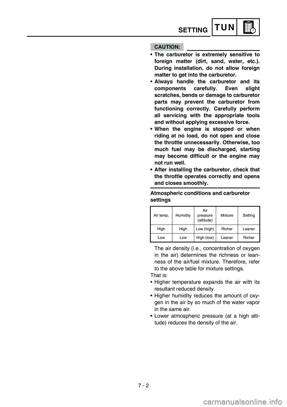
Atmospheric conditions and carburetor
settings
The air density (i.e., concentration of oxygen
in the air) determines the richness or lean-
ness of the air/fuel mixture. Therefore, refer
to the above table for mixture settings.
That is:
Higher temperature expands the air with its
resultant reduced density.
Higher humidity reduces the amount of oxy-
gen in the air by so much of the water vapor
in the same air.
Lower atmospheric pressure (at a high alti-
tude) reduces the density of the air.
Air temp. HumidityAir
pressure
(altitude)Mixture Setting
High High Low (high) Richer Leaner
Low Low High (low) Leaner Richer
SETTING