ACURA NSX 1991 Service Repair Manual
Manufacturer: ACURA, Model Year: 1991, Model line: NSX, Model: ACURA NSX 1991Pages: 1640, PDF Size: 60.48 MB
Page 141 of 1640
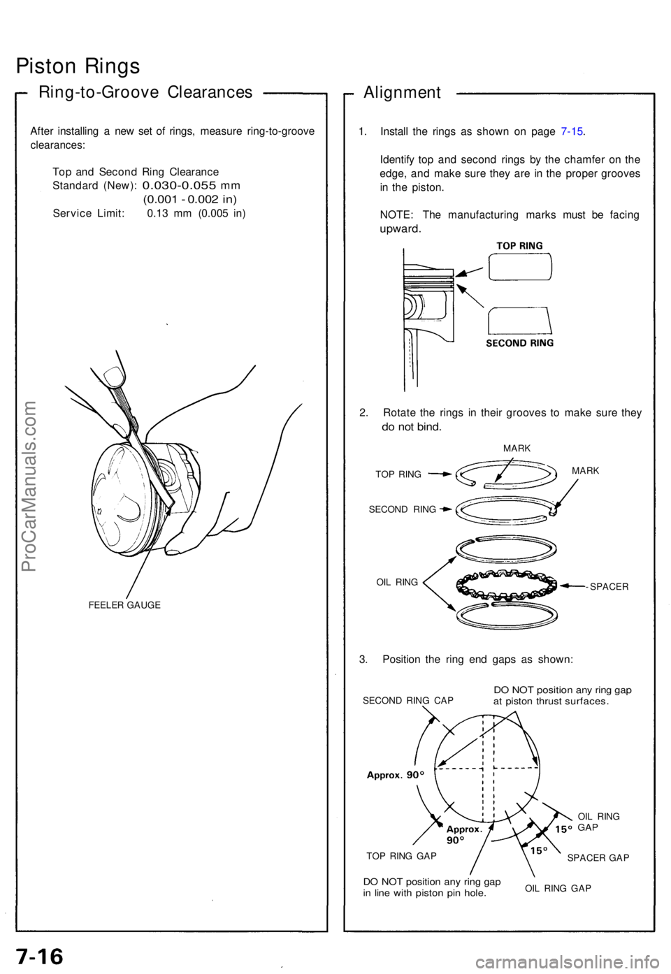
Piston Ring s
Ring-to-Groov e Clearance s
After installin g a ne w se t o f rings , measur e ring-to-groov e
clearances:
Top an d Secon d Rin g Clearanc e
Standar d (New) :
0.030-0.05 5 mm
(0.00 1 - 0.00 2 in )
Servic e Limit : 0.1 3 m m (0.00 5 in )
FEELE R GAUG E
Alignmen t
1. Instal l th e ring s a s show n o n pag e 7- 15.
Identif y to p an d secon d ring s b y th e chamfe r o n th e
edge , an d mak e sur e the y ar e i n th e prope r groove s
i n th e piston .
NOTE : Th e manufacturin g mark s mus t b e facin g
upward .
2. Rotat e th e ring s i n thei r groove s t o mak e sur e the y
do no t bind .
MAR K
TO P RIN G
SECON D RIN G
OI L RIN G MAR
K
- SPACE R
3. Positio n th e rin g en d gap s a s shown :
SECON D RIN G CA PDO NO T positio n an y rin g ga pat pisto n thrus t surfaces .
TOP RIN G GA P
DO NO T positio n an y rin g ga pin lin e wit h pisto n pi n hole .OIL RIN G GA P
SPACE
R GA P
OI
L RIN G
GAP
ProCarManuals.com
Page 142 of 1640
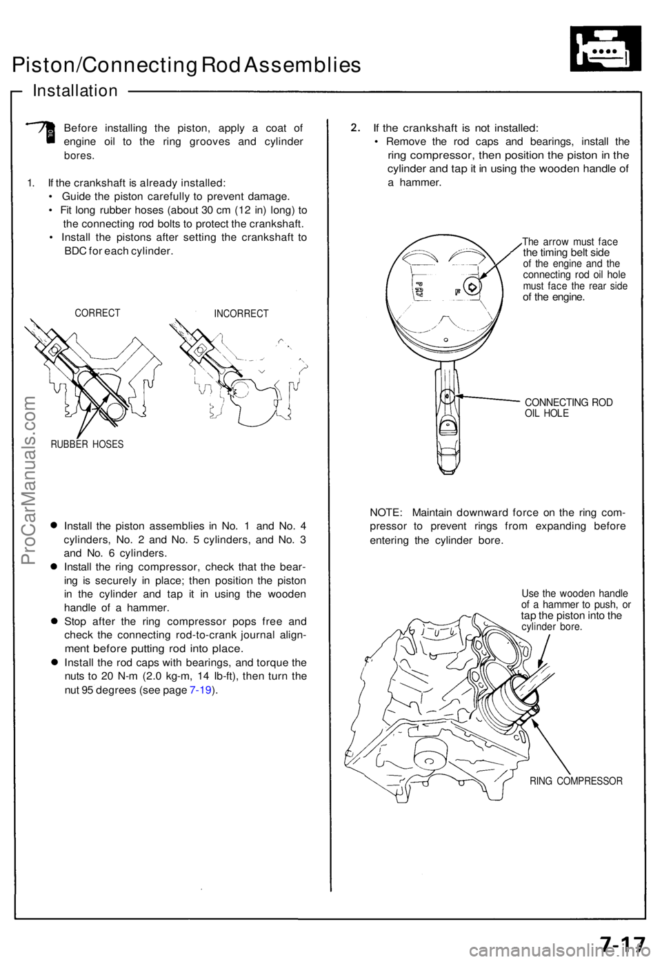
Piston/Connecting Ro d Assemblie s
Installation
Before installin g th e piston , appl y a coa t o f
engin e oi l t o th e rin g groove s an d cylinde r
bores.
1. I f th e crankshaf t i s alread y installed :
• Guid e th e pisto n carefull y t o preven t damage .
• Fi t lon g rubbe r hose s (abou t 3 0 c m (1 2 in ) long ) t o
th e connectin g ro d bolt s t o protec t th e crankshaft .
• Instal l th e piston s afte r settin g th e crankshaf t t o
BD C fo r eac h cylinder .
CORREC TINCORREC T
RUBBER HOSE S
Install th e pisto n assemblie s i n No . 1 an d No . 4
cylinders , No . 2 an d No . 5 cylinders , an d No . 3
an d No . 6 cylinders .
Instal l th e rin g compressor , chec k tha t th e bear -
in g i s securel y i n place ; the n positio n th e pisto n
i n th e cylinde r an d ta p i t i n usin g th e woode n
handl e of a hammer .
Sto p afte r th e rin g compresso r pop s fre e an d
chec k th e connectin g rod-to-cran k journa l align -
ment befor e puttin g ro d int o place .
Install th e ro d cap s wit h bearings , an d torqu e th e
nut s t o 2 0 N- m (2. 0 kg-m , 1 4 Ib-ft) , the n tur n th e
nu t 9 5 degree s (se e pag e 7-19 ).
If th e crankshaf t i s no t installed :
• Remov e th e ro d cap s an d bearings , instal l th e
ring compressor , the n positio n th e pisto n in th e
cylinde r an d ta p it i n usin g th e woode n handl e of
a hammer .
The arro w mus t fac ethe timin g bel t sid eof th e engin e an d th econnectin g ro d oi l hol emus t fac e th e rea r sid eof th e engine .
CONNECTIN G RO DOIL HOL E
NOTE : Maintai n downwar d forc e o n th e rin g com -
presso r t o preven t ring s fro m expandin g befor e
enterin g th e cylinde r bore .
Use th e woode n handl eof a hamme r t o push , o rtap th e pisto n int o th ecylinde r bore .
RING COMPRESSO R
ProCarManuals.com
Page 143 of 1640
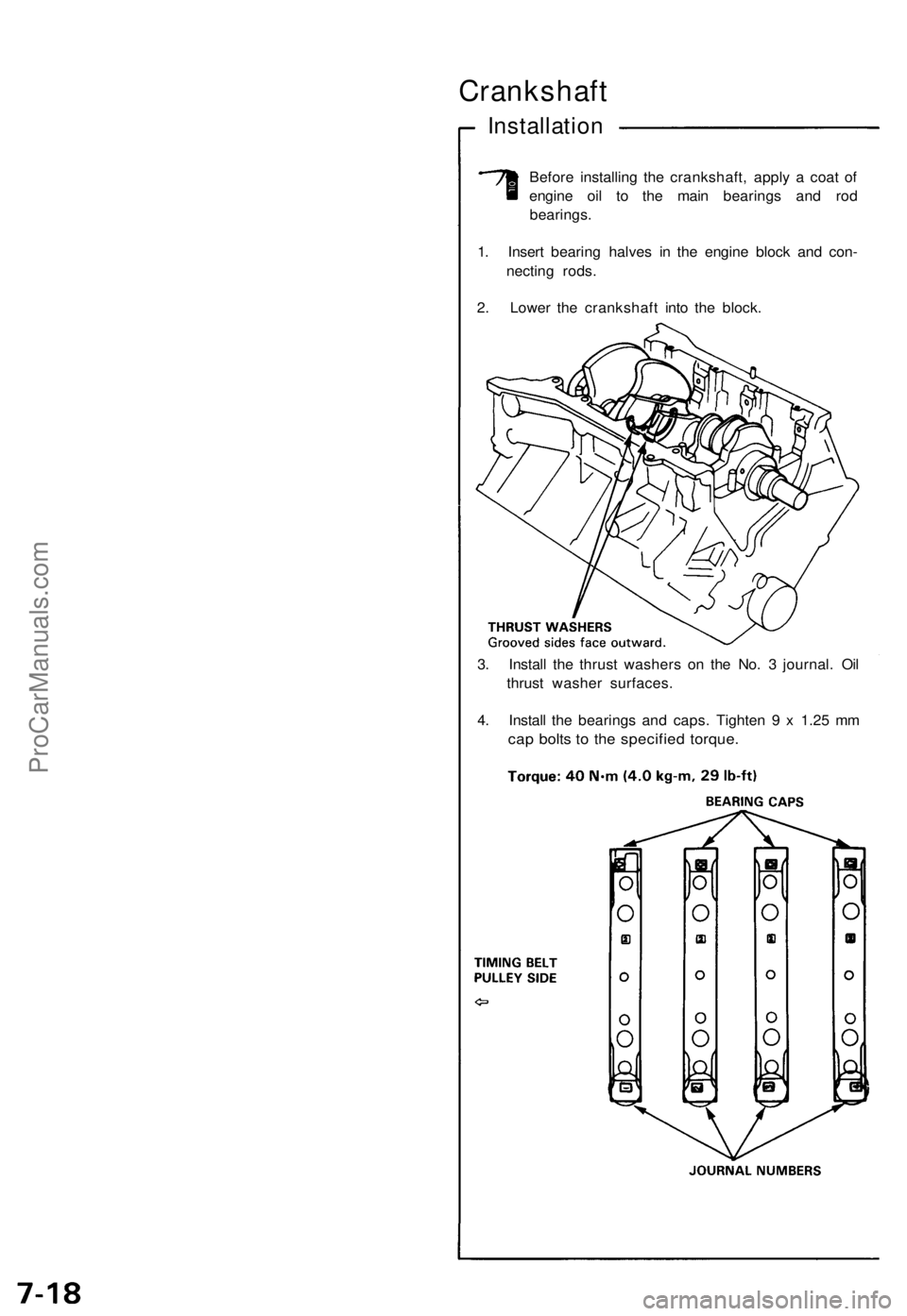
Crankshaft
Installation
Before installing the crankshaft, apply a coat of
engine oil to the main bearings and rod
bearings.
1. Insert bearing halves in the engine block and con-
necting rods.
2. Lower the crankshaft into the block.
3. Install the thrust washers on the No. 3 journal. Oil
thrust washer surfaces.
4. Install the bearings and caps. Tighten 9 x 1.25 mm
cap bolts to the specified torque.ProCarManuals.com
Page 144 of 1640
NOTE:
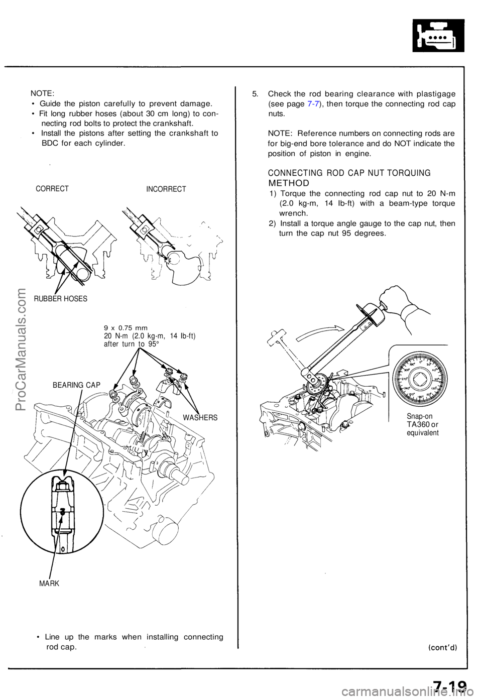
• Guid e th e pisto n carefull y t o preven t damage .
• Fi t lon g rubbe r hose s (abou t 3 0 c m long ) t o con -
nectin g ro d bolt s t o protec t th e crankshaft .
• Instal l th e piston s afte r settin g th e crankshaf t t o
BD C fo r eac h cylinder .
CORREC TINCORREC T
RUBBER HOSE S
9 x 0.7 5 mm20 N- m (2. 0 kg-m , 1 4 Ib-ft )
afte r tur n t o 95 °
MAR K
• Lin e u p th e mark s whe n installin g connectin g
rod cap .
5. Chec k th e ro d bearin g clearanc e wit h plastigag e
(se e pag e 7-7 ), the n torqu e th e connectin g ro d ca p
nuts .
NOTE : Referenc e number s o n connectin g rod s ar e
fo r big-en d bor e toleranc e an d d o NO T indicat e th e
positio n o f pisto n i n engine .
CONNECTIN G RO D CA P NU T TORQUIN G
METHOD
1) Torqu e th e connectin g ro d ca p nu t t o 2 0 N- m
(2. 0 kg-m , 1 4 Ib-ft ) wit h a beam-typ e torqu e
wrench .
2 ) Instal l a torqu e angl e gaug e t o th e ca p nut , the n
tur n th e ca p nu t 9 5 degrees .
Snap-onTA360 o requivalen t
BEARIN
G CA P
WASHERS
ProCarManuals.com
Page 145 of 1640
Crankshaft
Installation
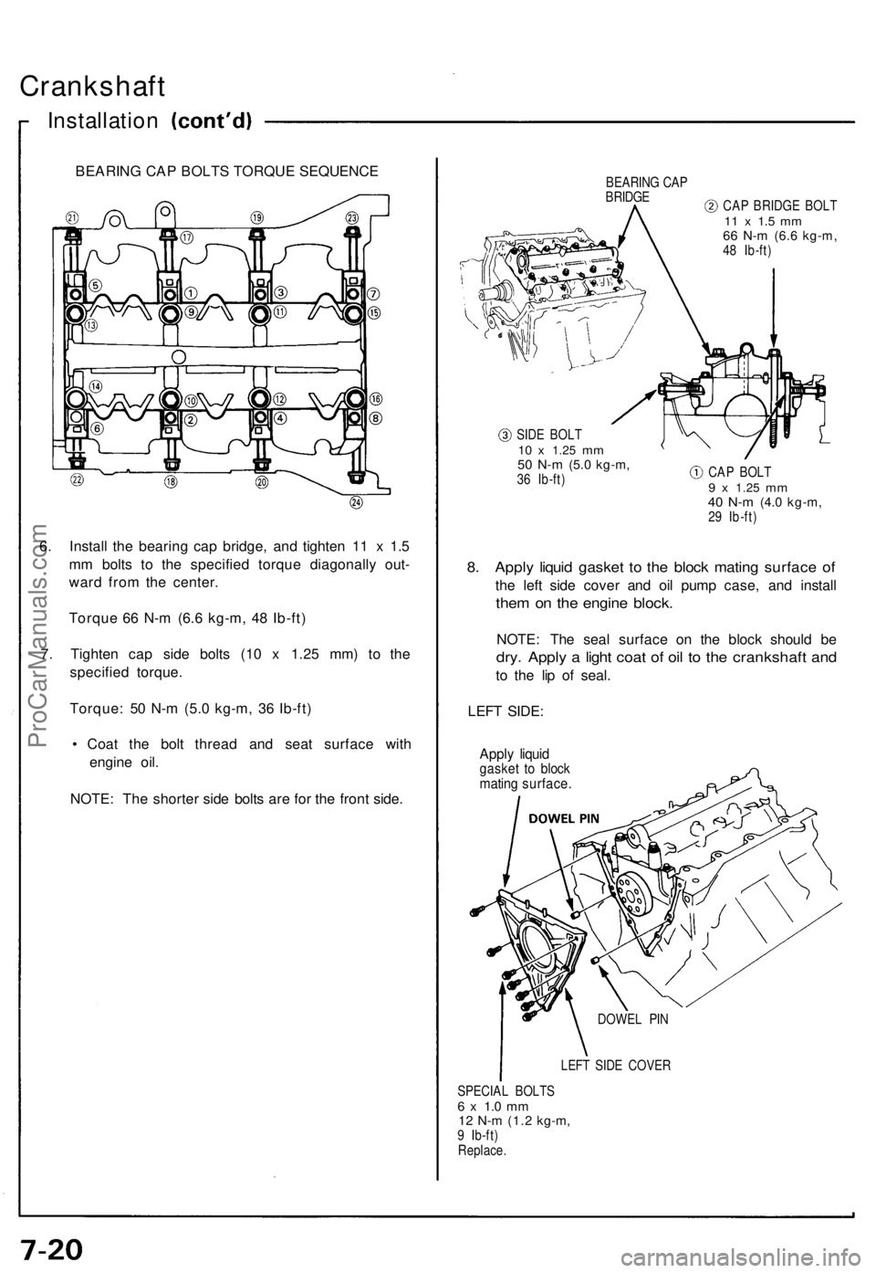
6. Instal l th e bearin g ca p bridge , an d tighte n 1 1 x 1. 5
m m bolt s t o th e specifie d torqu e diagonall y out -
war d fro m th e center .
Torqu e 6 6 N- m (6. 6 kg-m , 4 8 Ib-ft )
7 . Tighte n ca p sid e bolt s (1 0 x 1.2 5 mm ) t o th e
specifie d torque .
Torque : 5 0 N- m (5. 0 kg-m , 3 6 Ib-ft )
• Coa t th e bol t threa d an d sea t surfac e wit h
engin e oil .
NOTE : Th e shorte r sid e bolt s ar e fo r th e fron t side .
BEARIN G CA PBRIDG ECAP BRIDG E BOL T11 x 1. 5 m m66 N- m (6. 6 kg-m ,48 Ib-ft )
SID E BOL T
10 x 1.2 5 mm50 N- m (5. 0 kg-m ,36 Ib-ft ) CA
P BOL T9 x 1.2 5 mm40 N- m (4. 0 kg-m ,29 Ib-ft )
8. Appl y liqui d gaske t t o th e bloc k matin g surfac e o f
the lef t sid e cove r an d oi l pum p case , an d instal l
them o n th e engin e block .
NOTE : Th e sea l surfac e o n th e bloc k shoul d b e
dry . Appl y a ligh t coa t o f oi l t o th e crankshaf t an d
to th e li p o f seal .
LEF T SIDE :
Apply liqui dgaske t t o bloc kmatin g surface .
LEFT SID E COVE R
SPECIA L BOLT S
6 x 1. 0 m m12 N- m (1. 2 kg-m ,9 Ib-ft )
Replace . DOWE
L PI N
BEARIN G CA P BOLT S TORQU E SEQUENC E
ProCarManuals.com
Page 146 of 1640
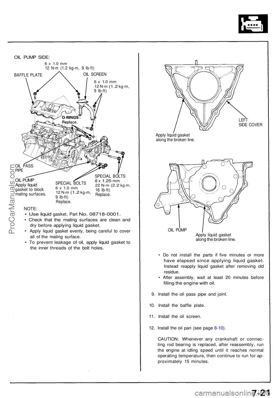
6 x 1. 0 m m12 N- m (1. 2 kg-m ,9 Ib-ft )
OIL PUM P
Appl y liqui d
gaske t t o bloc kmatin g surfaces .
SPECIAL BOLT S6 x 1. 0 m m12 N- m (1. 2 kg-m ,9 Ib-ft )Replace .
SPECIAL BOLT S8 x 1.2 5 mm22 N- m (2. 2 kg-m ,16 Ib-ft )Replace .
NOTE:
• Use liqui d gasket , Par t No. 08718-0001 .
• Chec k tha t th e matin g surface s ar e clea n an d
dry befor e applyin g liqui d gasket .
• Appl y liqui d gaske t evenly , bein g carefu l t o cove r
al l o f th e matin g surface .
• T o preven t leakag e o f oil , appl y liqui d gaske t t o
th e inne r thread s of the bol t holes .
LEFTSIDE COVE R
Apply liqui d gaske talong th e broke n line .
OIL PUM PApply liqui d gaske talong th e broke n line .
• D o no t instal l th e part s i f fiv e minute s o r mor e
have elapse d sinc e applyin g liqui d gasket .
Instead reappl y liqui d gaske t afte r removin g ol d
residue .
• Afte r assembly , wai t a t leas t 2 0 minute s befor e
filling th e engin e wit h oil .
9. Instal l th e oi l pas s pip e an d joint .
10 . Instal l th e baffl e plate .
11 . Instal l th e oi l screen .
12 . Instal l th e oi l pa n (se e pag e 8-10 ).
CAUTION : Wheneve r an y crankshaf t o r connec -
tin g ro d bearin g i s replaced , afte r reassembly , ru n
th e engin e a t idlin g spee d unti l i t reache s norma l
operatin g temperature , the n continu e t o ru n fo r ap -
proximatel y 1 5 minutes .
OIL PUM P SIDE :
6 x 1. 0 m m12 N- m (1. 2 kg-m , 9 Ib-ft )
OIL SCREE NBAFFLE PLAT E
OIL PAS SPIPE
ProCarManuals.com
Page 147 of 1640
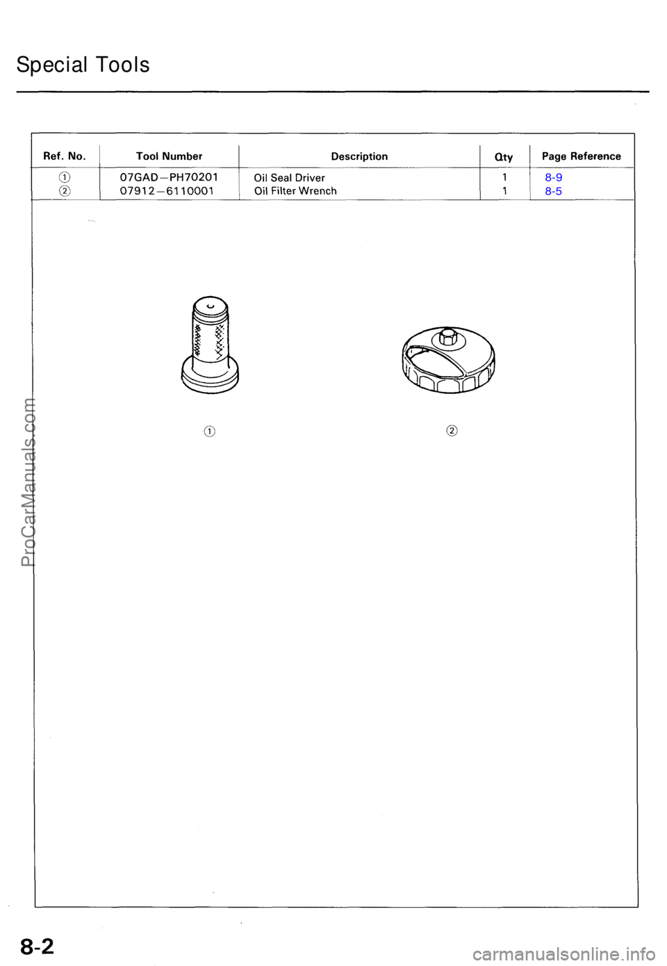
Special Tool s
8-9
8-5
ProCarManuals.com
Page 148 of 1640
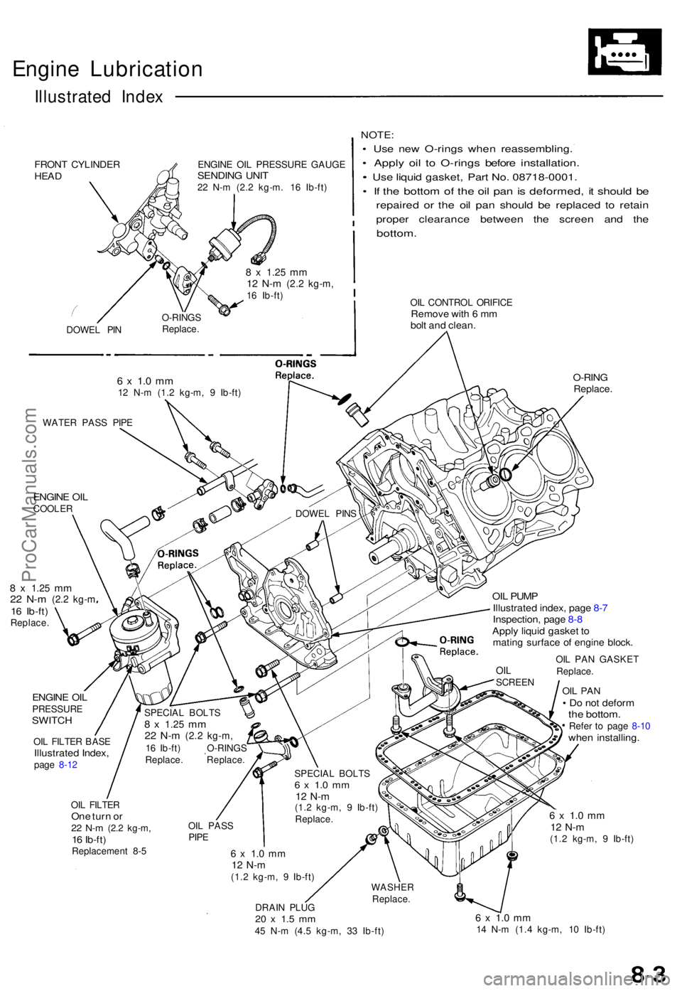
Engine Lubricatio n
Illustrated Inde x
FRON T CYLINDE RHEADENGIN E OI L PRESSUR E GAUG ESENDIN G UNI T22 N- m (2. 2 kg-m . 1 6 Ib-ft )
NOTE :
• Us e ne w O-ring s whe n reassembling .
• Appl y oi l t o O-ring s befor e installation .
• Us e liqui d gasket , Par t No . 08718-0001 .
• I f th e botto m o f th e oi l pa n is deformed , i t shoul d b e
repaire d o r th e oi l pa n shoul d b e replace d t o retai n
prope r clearanc e betwee n th e scree n an d th e
bottom .
OIL CONTRO L ORIFIC ERemove wit h 6 m mbol t an d clean .
O-RIN GReplace .
8 x 1.2 5 mm22 N- m (2. 2 kg- m16 Ib-ft )Replace .
ENGINE OI LPRESSUR ESWITCH
OIL FILTE R BAS EIllustrate d Index ,page 8-1 2
OIL PUM PIllustrate d index , pag e 8- 7Inspection , pag e 8 -8Appl y liqui d gaske t t omatin g surfac e o f engin e block .
OIL PA N GASKE T
Replace .
OIL PA N• D o no t defor mthe bottom .Refer t o pag e 8-1 0whe n installing .
OIL FILTE ROne tur n o r22 N- m (2. 2 kg-m ,16 Ib-ft )Replacemen t 8- 5
6 x 1. 0 m m12 N- m(1.2 kg-m , 9 Ib-ft )
6 x 1. 0 m m12 N- m(1.2 kg-m , 9 Ib-ft )
DRAI N PLU G
20 x 1. 5 m m45 N- m (4. 5 kg-m , 3 3 Ib-ft )
6 x 1. 0 m m14 N- m (1. 4 kg-m , 1 0 Ib-ft )
ENGIN E OI LCOOLE R
WATE
R PAS S PIP E
DOWEL PIN S
SPECIA L BOLT S
8 x 1.2 5 mm22 N- m (2. 2 kg-m ,16 Ib-ft ) O-RING S
Replace . Replace .
OI L PAS S
PIPE
SPECIA L BOLT S6 x 1. 0 m m12 N- m(1.2 kg-m , 9 Ib-ft )
Replace .
6 x 1. 0 m m12 N- m (1. 2 kg-m , 9 Ib-ft )
DOWE
L PI N O-RING
S
Replace .
8 x 1.2 5 mm12 N- m (2. 2 kg-m ,16 Ib-ft )
OILSCREE N
WASHE R
Replace .
ProCarManuals.com
Page 149 of 1640
Engine Oil
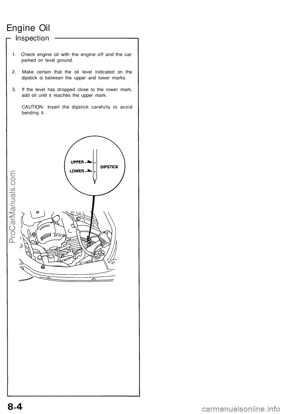
Inspection
1. Check engine oil with the engine off and the car
parked on level ground.
2. Make certain that the oil level indicated on the
dipstick is between the upper and lower marks.
3. If the level has dropped close to the lower mark,
add oil until it reaches the upper mark.
CAUTION: Insert the dipstick carefully to avoid
bending it.ProCarManuals.com
Page 150 of 1640
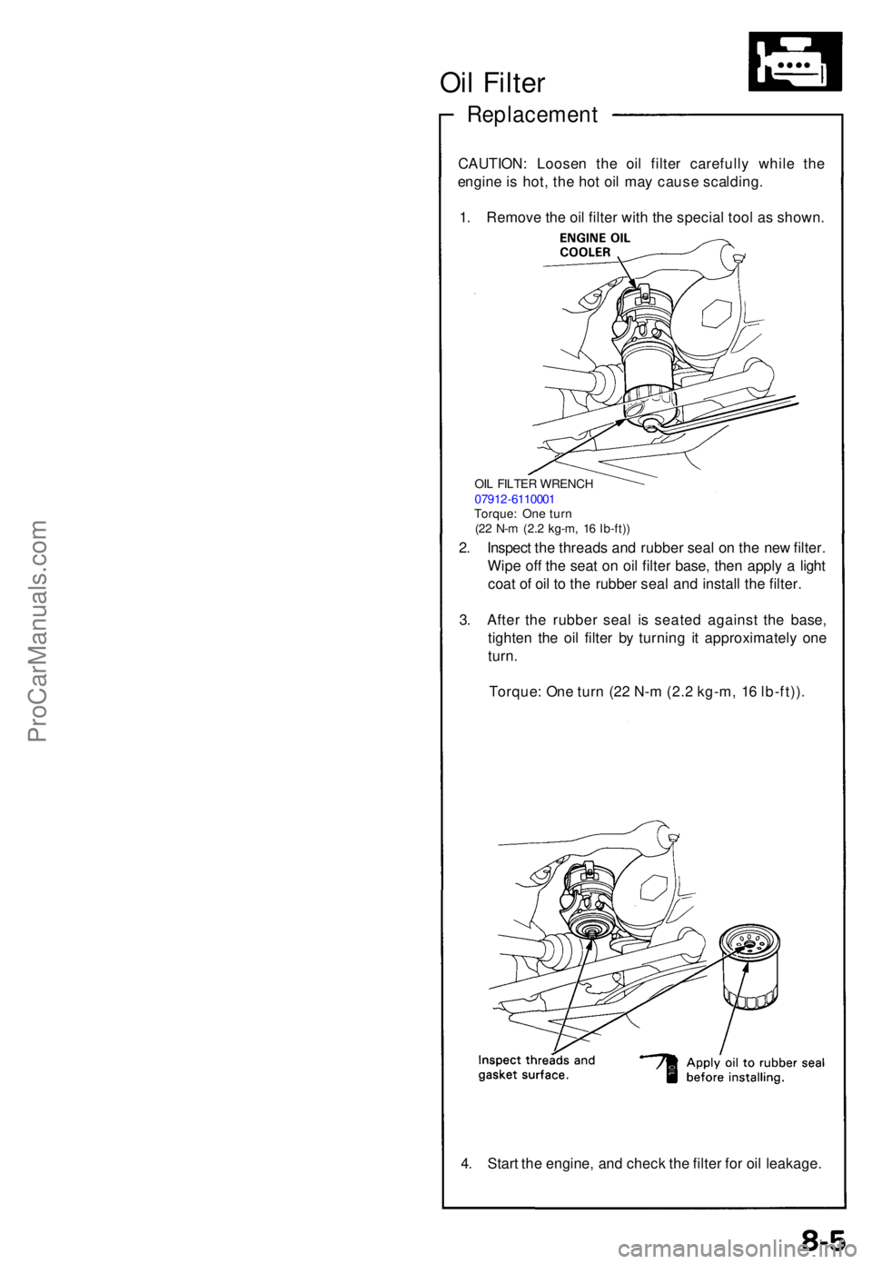
Oil Filte r
Replacemen t
CAUTION: Loose n th e oi l filte r carefull y whil e th e
engin e is hot , th e ho t oi l ma y caus e scalding .
1 . Remov e th e oi l filte r wit h th e specia l too l a s shown .
2 . Inspec t th e thread s an d rubbe r sea l o n th e ne w filter .
Wip e of f th e sea t o n oi l filte r base , the n appl y a ligh t
coa t o f oi l t o th e rubbe r sea l an d instal l th e filter .
3 . Afte r th e rubbe r sea l i s seate d agains t th e base ,
tighte n th e oi l filte r b y turnin g i t approximatel y on e
turn .
Torque : On e tur n (2 2 N- m (2. 2 kg-m , 1 6 lb-ft)) .
OIL FILTE R WRENC H
0791 2-611000 1
Torque : On e tur n
(2 2 N- m (2. 2 kg-m , 1 6 lb-ft) )
4. Star t th e engine , an d chec k th e filte r fo r oi l leakage .
ProCarManuals.com