ACURA NSX 1991 Service Repair Manual
Manufacturer: ACURA, Model Year: 1991, Model line: NSX, Model: ACURA NSX 1991Pages: 1640, PDF Size: 60.48 MB
Page 121 of 1640
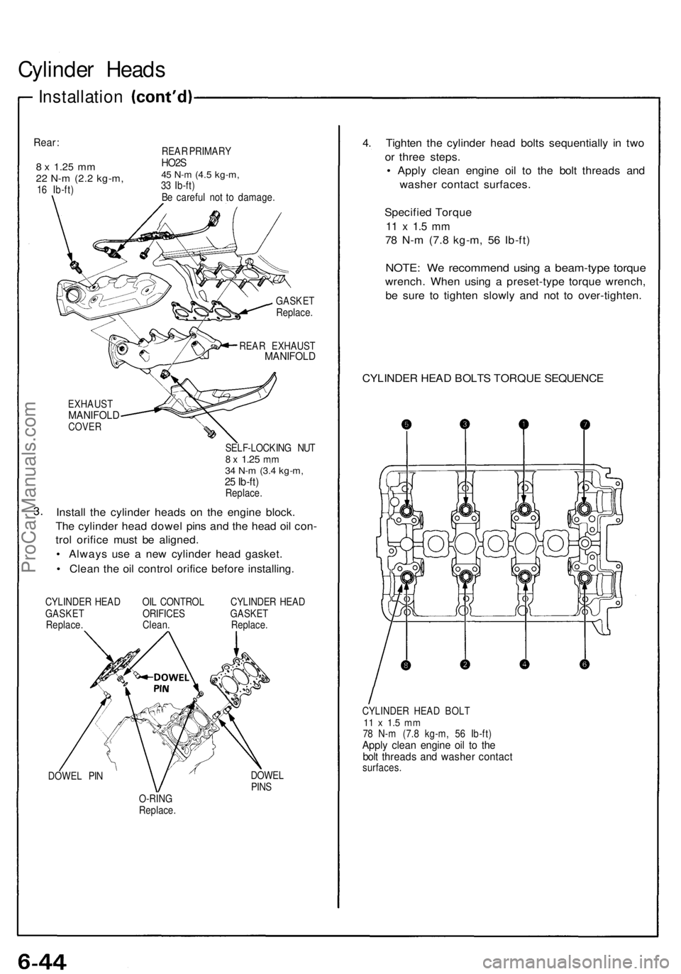
Cylinder Head s
Installatio n
Rear:
8 x 1.2 5 mm22 N- m (2. 2 kg-m ,16 Ib-ft ) REA
R PRIMAR Y
HO2S45 N- m (4. 5 kg-m ,33 Ib-ft )
B e carefu l no t t o damage .
GASKE T
Replace .
REA R EXHAUS T
MANIFOLD
EXHAUSTMANIFOL DCOVER
SELF-LOCKIN G NU T8 x 1.2 5 mm34 N- m (3. 4 kg-m ,25 Ib-ft )Replace .
Install th e cylinde r head s o n th e engin e block .
Th e cylinde r hea d dowe l pin s an d th e hea d oi l con -
tro l orific e mus t b e aligned .
• Alway s us e a ne w cylinde r hea d gasket .
• Clea n th e oi l contro l orific e befor e installing .
CYLINDE R HEA D OI L CONTRO L CYLINDE R HEA D
GASKE T ORIFICE S GASKE T
Replace . Clean . Replace .
DOWE L PI N DOWE
L
PIN S
O-RIN G
Replace .
4. Tighte n th e cylinde r hea d bolt s sequentiall y i n tw o
o r thre e steps .
• Appl y clea n engin e oi l t o th e bol t thread s an d
washe r contac t surfaces .
Specifie d Torqu e
11 x 1. 5 m m
78 N- m (7. 8 kg-m , 5 6 Ib-ft )
NOTE : W e recommen d usin g a beam-typ e torqu e
wrench . Whe n usin g a preset-typ e torqu e wrench ,
b e sur e t o tighte n slowl y an d no t t o over-tighten .
CYLINDE R HEA D BOLT S TORQU E SEQUENC E
CYLINDER HEA D BOL T11 x 1. 5 m m78 N- m (7. 8 kg-m , 5 6 Ib-ft )Apply clea n engin e oi l t o th ebolt thread s an d washe r contac tsurfaces .
ProCarManuals.com
Page 122 of 1640
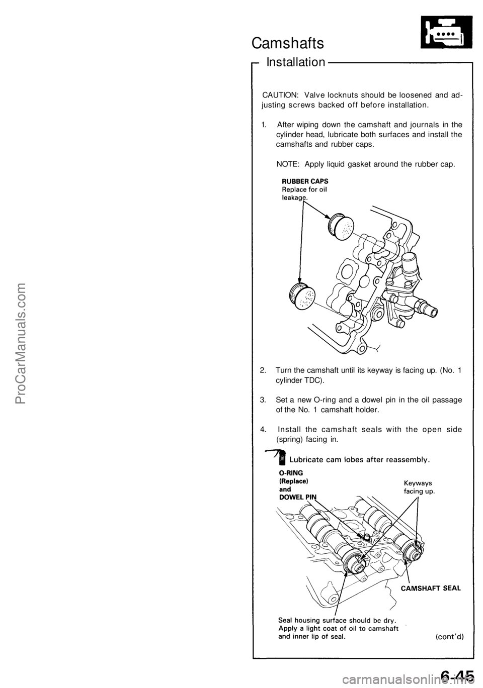
Camshafts
Installation
CAUTION : Valv e locknut s shoul d b e loosene d an d ad -
justin g screw s backe d of f befor e installation .
1 . Afte r wipin g dow n th e camshaf t an d journal s i n th e
cylinde r head , lubricat e bot h surface s an d instal l th e
camshaft s an d rubbe r caps.
NOTE : Appl y liqui d gaske t aroun d th e rubbe r cap .
2 . Tur n th e camshaft until it s keywa y i s facin g up . (No . 1
cylinde r TDC) .
3 . Se t a ne w O-rin g an d a dowe l pi n i n th e oi l passag e
o f th e No . 1 camshaf t holder .
4 . Instal l th e camshaf t seal s wit h th e ope n sid e
(spring ) facin g in .
ProCarManuals.com
Page 123 of 1640
Camshafts
Installation
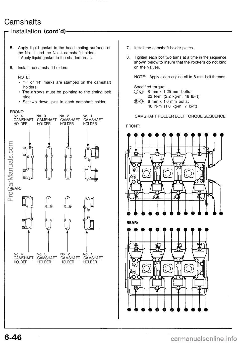
5. Apply liquid gasket to the head mating surfaces of
the No. 1 and the No. 4 camshaft holders.
- Apply liquid gasket to the shaded areas.
6. Install the camshaft holders.
NOTE:
• "F" or "R" marks are stamped on the camshaft
holders.
• The arrows must be pointing to the timing belt
side.
• Set two dowel pins in each camshaft holder.
FRONT:
No. 4 No. 3 No. 2 No. 1
CAMSHAFT CAMSHAFT CAMSHAFT CAMSHAFT
HOLDER HOLDER HOLDER HOLDER
REAR:
No. 4 No. 3 No. 2 No. 1
CAMSHAFT CAMSHAFT CAMSHAFT CAMSHAFT
HOLDER HOLDER HOLDER HOLDER
7. Install the camshaft holder plates.
8. Tighten each bolt two turns at a time in the sequence
shown below to insure that the rockers do not bind
on the valves.
NOTE: Apply clean engine oil to 8 mm bolt threads.
Specified torque:
8 mm x 1.25 mm bolts:
22 N-m (2.2 kg-m, 16 Ib-ft)
6 mm x 1.0 mm bolts:
10 N-m (1.0 kg-m, 7 Ib-ft)
CAMSHAFT HOLDER BOLT TORQUE SEQUENCE
FRONT:ProCarManuals.com
Page 124 of 1640
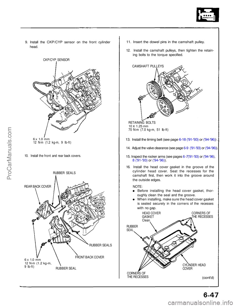
9. Install the CKP/CYP sensor on the front cylinder
head.
CKP/CYP SENSOR
6 x 1.0 mm
12 N·m (1.2 kg-m, 9 Ib-ft)
10. Install the front and rear back covers.
RUBBER SEALS
REAR BACK COVER
6 x 1.0 mm
12 N·m
(1.2 kg-m,
9 Ib-ft) RUBBER SEALS
FRONT BACK COVER
RUBBER SEAL
11. Insert the dowel pins in the camshaft pulley.
12. Install the camshaft pulleys, then tighten the retain- ing bolts to the torque specified.
CAMSHAFT PULLEYS
13. Install the timing belt (see page 6-18 ('91-'93) or ('94-'96)) .
14. Adjust the valve clearance (see page 6-9 ('91-'93) or ('94-'96)).
15. Inspect the rocker arms (see pages
6-7('91-'93) or ('94-'96),8 ('91-'93) or ('94-'96)).
16. Install the head cover gasket in the groove of the
cylinder head cover. Seat the recesses for the
camshaft first, then work it into the groove around
the outside edges.
NOTE:
Before installing the head cover gasket, thor-
oughly clean the seal and the groove. When installing, make sure the head cover gasket
is seated securely in the corners of the recesses
with no gap.
HEAD COVER
GASKET Clean.
RUBBER
SEAL
CORNERS OF
THE RECESSES
CYLINDER HEAD
COVER
CORNERS OF THE RECESSES
(cont'd)
RETAINING BOLTS
10 x
1.25
mm
70 N·m (7.0 kg-m, 51 Ib-ft)ProCarManuals.com
Page 125 of 1640
Camshafts
Installation
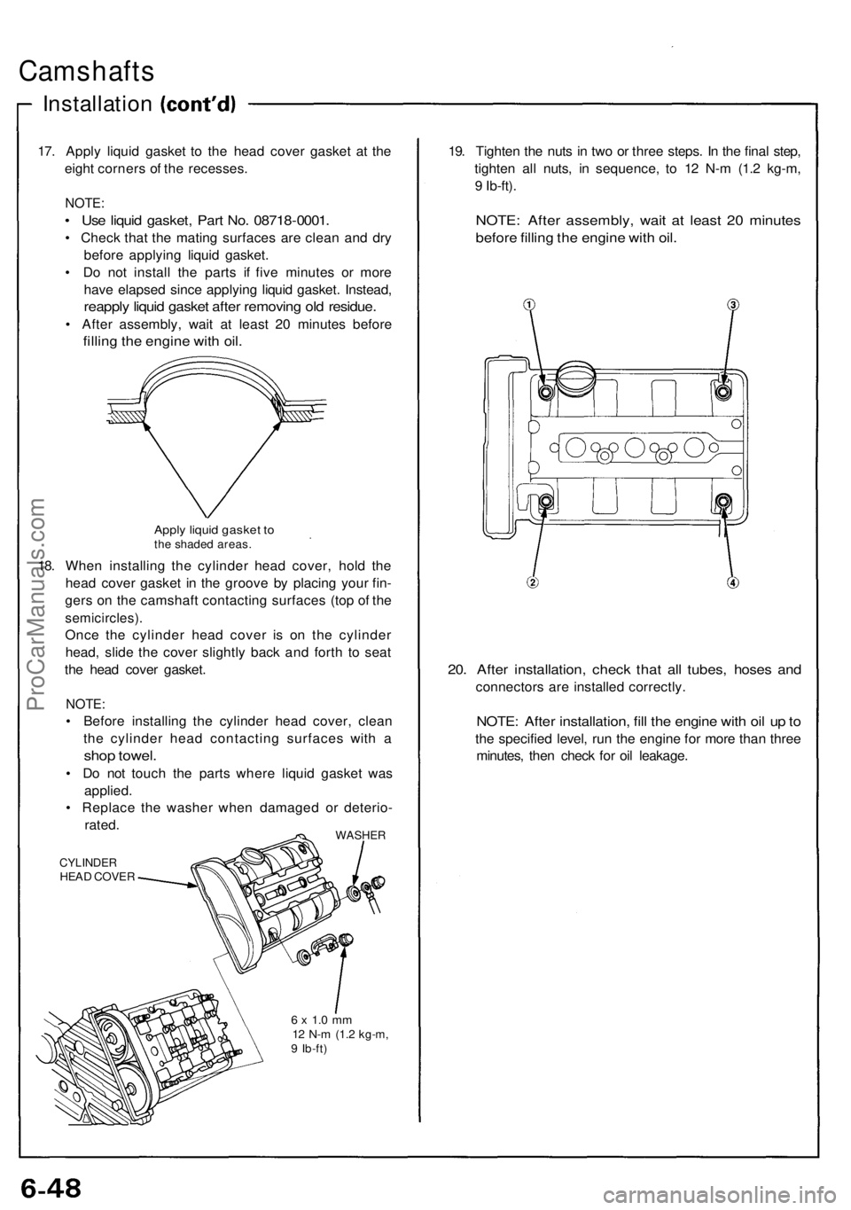
17. Appl y liqui d gaske t t o th e hea d cove r gaske t a t th e
eigh t corner s o f th e recesses .
NOTE:
• Us e liqui d gasket , Par t No . 0871 8-0001 .
• Chec k tha t th e matin g surface s ar e clea n an d dr y
befor e applyin g liqui d gasket .
• D o no t instal l th e part s i f fiv e minute s o r mor e
hav e elapse d sinc e applyin g liqui d gasket . Instead ,
reapply liqui d gaske t afte r removin g ol d residue .
• Afte r assembly , wai t a t leas t 2 0 minute s befor e
filling th e engin e wit h oil .
Appl y liqui d gaske t t oth e shade d areas .
18. Whe n installin g th e cylinde r hea d cover , hol d th e
hea d cove r gaske t i n th e groov e b y placin g you r fin -
ger s o n th e camshaf t contactin g surface s (to p o f th e
semicircles) .
Once th e cylinde r hea d cove r i s o n th e cylinde r
head , slid e th e cove r slightl y bac k an d fort h t o sea t
th e hea d cove r gasket .
NOTE:
• Befor e installin g th e cylinde r hea d cover , clea n
th e cylinde r hea d contactin g surface s wit h a
sho p towel .
• D o no t touc h th e part s wher e liqui d gaske t wa s
applied .
• Replac e th e washe r whe n damage d o r deterio -
rated .
WASHE R
CYLINDE RHEAD COVE R
6 x 1. 0 m m12 N- m (1. 2 kg-m ,9 Ib-ft )
19. Tighte n th e nut s i n tw o o r thre e steps . I n th e fina l step ,
tighte n al l nuts , i n sequence , t o 1 2 N- m (1. 2 kg-m ,
9 Ib-ft) .
NOTE : Afte r assembly , wai t a t leas t 2 0 minute s
before fillin g th e engin e wit h oil .
20. Afte r installation , chec k tha t al l tubes , hose s an d
connector s ar e installe d correctly .
NOTE: Afte r installation , fil l th e engin e wit h oi l u p to
th e specifie d level , ru n th e engin e fo r mor e tha n thre e
minutes , the n chec k fo r oi l leakage .
ProCarManuals.com
Page 126 of 1640
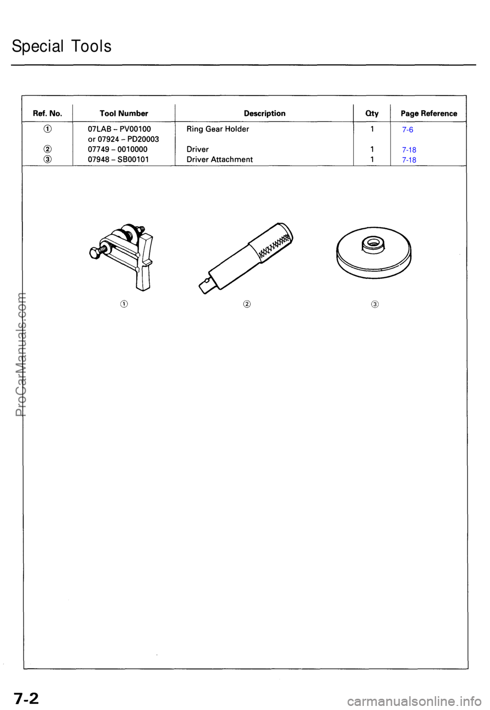
Special Tool s
7-6
7-1 8
7-1 8
ProCarManuals.com
Page 127 of 1640
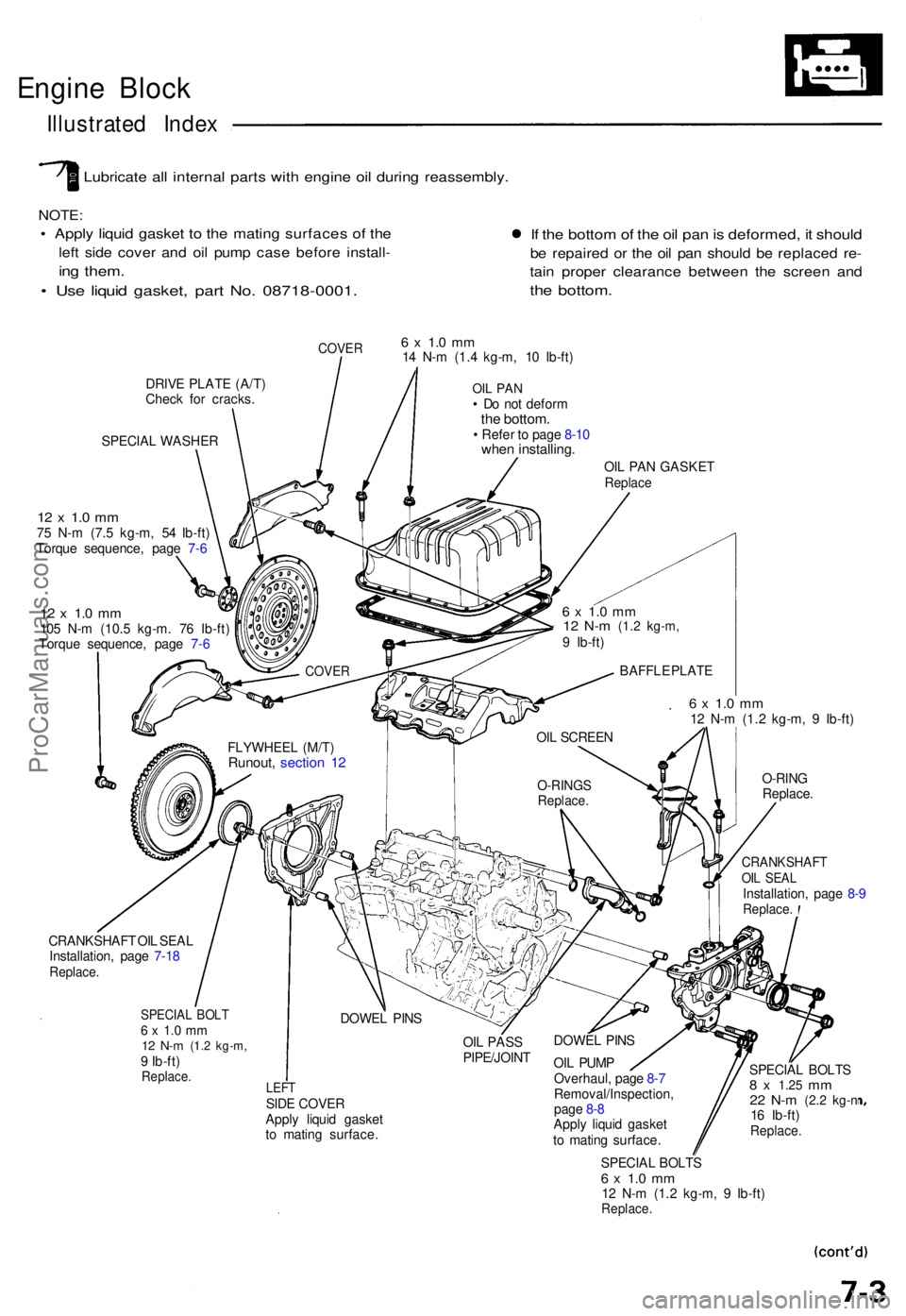
Engine Bloc k
Illustrate d Inde x
Lubricat e al l interna l part s wit h engin e oi l durin g reassembly .
NOTE:
• Appl y liqui d gaske t t o th e matin g surface s o f th e
left sid e cove r an d oi l pum p cas e befor e install -
ing them .
• Us e liqui d gasket , par t No . 08718-0001 .
If th e botto m of th e oi l pa n is deformed , i t shoul d
be repaire d o r th e oi l pa n shoul d b e replace d re -
tain prope r clearanc e betwee n th e scree n an d
the bottom .
COVER
DRIVE PLAT E (A/T )
Chec k fo r cracks .
SPECIA L WASHE R
12 x 1. 0 m m75 N- m (7. 5 kg-m , 5 4 Ib-ft )
Torqu e sequence , pag e 7- 6
12 x 1. 0 m m105 N- m (10. 5 kg-m . 7 6 Ib-ft )
Torqu e sequence , pag e 7- 6
6 x 1. 0 m m14 N- m (1. 4 kg-m , 1 0 Ib-ft )
OIL PA N• D o no t defor mthe bottom .• Refe r t o pag e 8-1 0whe n installing .
OIL PA N GASKE TReplace
6 x 1. 0 m m12 N- m (1. 2 kg-m , 9 Ib-ft )
O-RIN G
Replace .
CRANKSHAF TOIL SEA LInstallation , pag e 8- 9Replace .
CRANKSHAF T OI L SEA L
Installation , pag e 7-1 8
Replace .
SPECIAL BOL T6 x 1. 0 m m12 N- m (1. 2 kg-m ,9 Ib-ft )Replace .
OIL PAS S
PIPE/JOIN T
LEFTSIDE COVE R
Appl y liqui d gaske t
t o matin g surface . DOWE
L PIN S
OI L PUM P
Overhaul , pag e 8- 7
Removal/Inspection ,
pag e 8- 8
Appl y liqui d gaske t
t o matin g surface . SPECIA
L BOLT S
8 x 1.2 5 mm22 N- m (2. 2 kg- n16 Ib-ft )Replace .
SPECIAL BOLT S6 x 1. 0 m m12 N- m (1. 2 kg-m , 9 Ib-ft )Replace .
DOWEL PIN S
O-RING SReplace .
OIL SCREE N
FLYWHEE L (M/T )
Runout , sectio n 1 2
BAFFL E PLAT E
6 x 1. 0 m m12 N- m (1. 2 kg-m ,9 Ib-ft )
COVE R
ProCarManuals.com
Page 128 of 1640
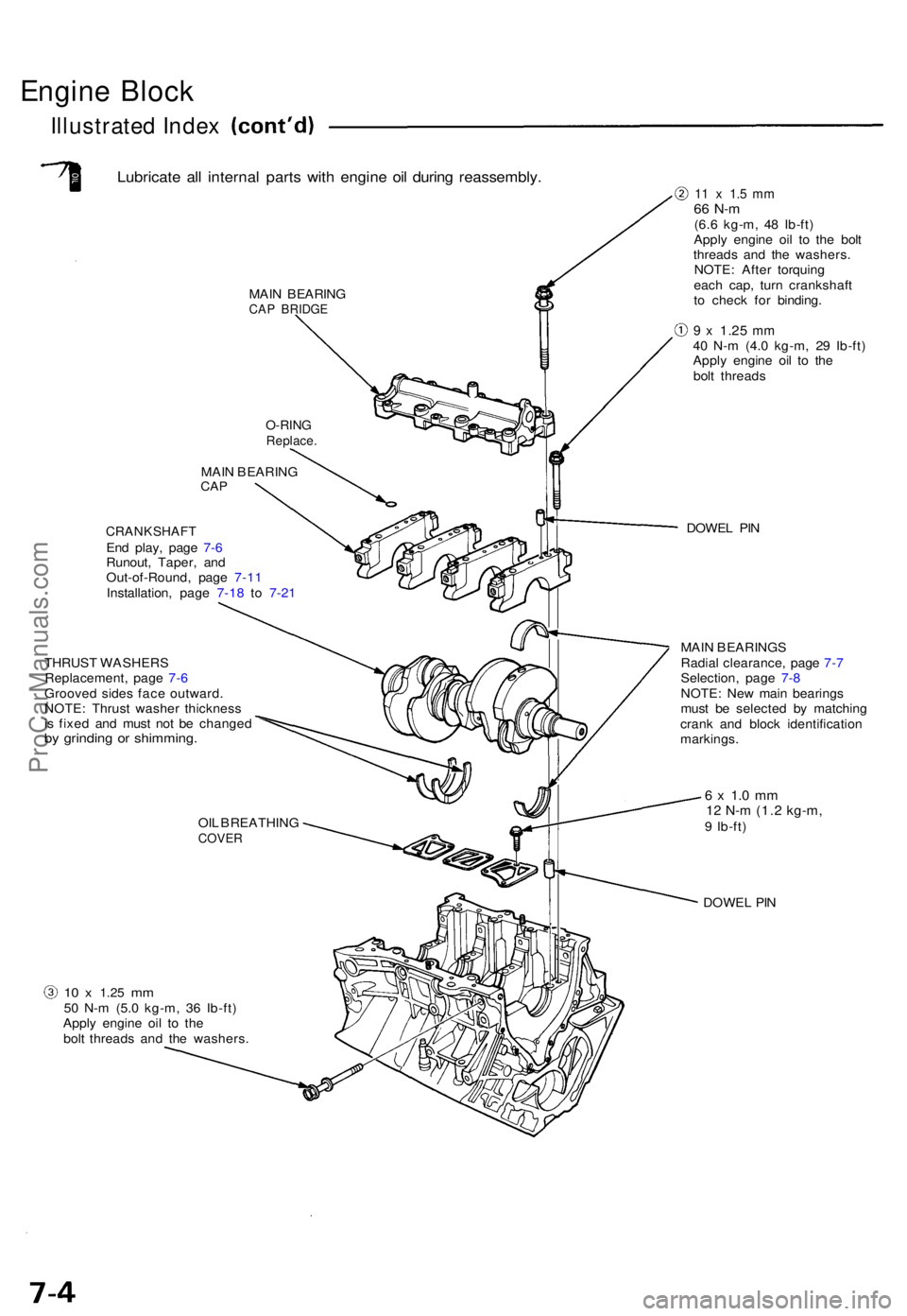
Engine Bloc k
Illustrated Index
Lubricat e al l interna l part s wit h engin e oi l durin g reassembly .
MAIN BEARIN GCAP BRIDG E
10 x 1.2 5 mm50 N- m (5. 0 kg-m , 3 6 Ib-ft )
Appl y engin e oi l t o th e
bol t thread s an d th e washers .
MAI
N BEARIN G
CAP
CRANKSHAF TEnd play , pag e 7- 6
Runout , Taper , an d
Out-of-Round , pag e 7-1 1
Installation , pag e 7-1 8 to 7-2 1
THRUS T WASHER S
Replacement , pag e 7- 6
Groove d side s fac e outward .
NOTE : Thrus t washe r thicknes s
i s fixe d an d mus t no t b e change d
by grindin g o r shimming .
11 x 1. 5 m m66 N- m(6.6 kg-m , 4 8 Ib-ft )
Appl y engin e oi l t o th e bol t
threads and th e washers .
NOTE : Afte r torquin g
eac h cap , tur n crankshaf t
t o chec k fo r binding .
9 x 1.2 5 mm40 N- m (4. 0 kg-m , 2 9 Ib-ft )
Appl y engin e oi l t o th e
bol t thread s
DOWE L PI N
MAI N BEARING S
Radia l clearance , pag e 7- 7
Selection , pag e 7- 8
NOTE : Ne w mai n bearing s
mus t b e selecte d b y matchin g
cran k an d bloc k identificatio n
markings .
6 x 1. 0 m m12 N- m (1. 2 kg-m ,9 Ib-ft )
DOWE L PI N
OI
L BREATHIN GCOVER
O-RINGReplace .
ProCarManuals.com
Page 129 of 1640
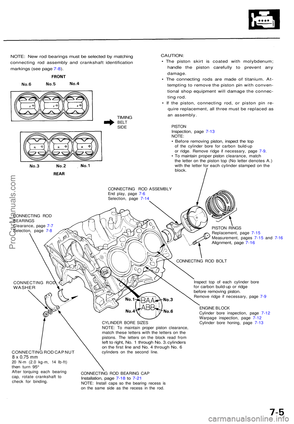
NOTE: Ne w ro d bearing s mus t b e selecte d b y matchin g
connectin g ro d assembl y an d crankshaf t identificatio n
markings (se e pag e 7-8 ).
TIMIN GBELTSIDE
CAUTION :
• Th e pisto n skir t i s coate d wit h molybdenum ;
handle th e pisto n carefull y t o preven t an y
damage .
• Th e connectin g rod s ar e mad e o f titanium . At -
temptin g t o remov e th e pisto n pi n wit h conven -
tional sho p equipmen t wil l damag e th e connec -
ting rod .
• I f th e piston , connectin g rod , o r pisto n pi n re -
quir e replacement , al l thre e mus t b e replace d a s
an assembly .
PISTONInspection , pag e 7-13NOTE :• Befor e removin g piston , inspec t th e to pof th e cylinde r bor e fo r carbo n build-u p
o r ridge . Remov e ridg e i f necessary , pag e 7-9 .
• T o maintai n prope r pisto n clearance , matc hthe lette r o n th e pisto n to p (N o lette r denote s A. )with th e lette r fo r eac h cylinde r stampe d o n th eblock .
CONNECTIN G RO D ASSEMBL Y
En d play , pag e 7- 6
Selection , pag e 7-1 4
CONNECTIN G RO D
BEARING SClearance , pag e 7- 7
Selection , pag e 7- 8
CONNECTIN G RO D
WASHE R
CONNECTIN G RO D CA P NU T8 x 0.75 mm20 N- m (2. 0 kg-m , 1 4 Ib-ft )then tur n 95 °Afte r torquin g eac h bearin g
cap , rotat e crankshaf t t o
chec k fo r binding .
CYLINDE R BOR E SIZE SNOTE : T o maintai n prope r pisto n clearance ,match thes e letter s wit h th e letter s o n th epistons . Th e letter s o n th e bloc k rea d fro mleft t o right , No . 1 throug h No . 3 . cylinder son th e firs t lin e an d No . 4 throug h No . 6cylinder s o n th e secon d line .
CONNECTIN G RO D BEARIN G CA P
Installation , pag e 7-1 8 to 7-2 1NOTE : Instal l cap s s o th e bearin g reces s i s
o n th e sam e sid e a s th e reces s i n th e rod . PISTO
N RING S
Replacement , pag e 7-1 5
Measurement , page s 7-1 5 an d 7-1 6
Alignment , pag e 7-1 6
CONNECTIN G RO D BOL T
Inspec t to p o f eac h cylinde r bor e
for carbo n build-u p o r ridg ebefor e removin g piston .Remov e ridg e i f necessary , pag e 7- 9
ENGIN E BLOC K
Cylinde r bor e inspection , pag e 7-12
Warpag e inspection , pag e 7-12
Cylinde r bor e honing , pag e 7-13
ProCarManuals.com
Page 130 of 1640
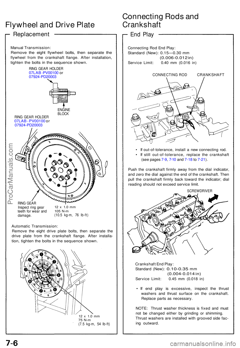
Flywheel an d Driv e Plat e
Replacemen t
Manual Transmission :
Remove th e eigh t flywhee l bolts , the n separat e th e
flywhee l fro m th e crankshaf t flange . Afte r installation ,
tighten th e bolt s i n th e sequenc e shown .
RING GEA R HOLDE R07LAB -PV0010 0 o r
0792 4-PD2000 3
RING GEA R HOLDE R07LAB - PV00100 or
0792 4-PD2000 3
ENGINEBLOCK
RING GEA RInspec t rin g gea rteeth fo r wea r an ddamage .
12 x 1. 0 m m105 N- m(10. 5 kg-m , 7 6 Ib-ft )
Automati c Transmission :
Remov e th e eigh t driv e plat e bolts , the n separat e th e
driv e plat e fro m th e crankshaf t flange . Afte r installa -
tion, tighte n th e bolt s i n th e sequenc e shown .
12 x 1. 0 m m75 N- m(7.5 kg-m , 5 4 Ib-ft )
Connectin g Rod s an d
Crankshaf t
End Pla y
Connectin g Ro d En d Play :
Standar d (New) : 0.15—0.3 0 m m
(0.006-0.01 2 in )
Servic e Limit : 0.4 0 m m (0.01 6 in )
CONNECTIN G RO D CRANKSHAF T
• I f out-of-tolerance , instal l a ne w connectin g rod .
• I f stil l out-of-tolerance , replac e th e crankshaf t
(se e page s 7-9 , 7-1 0 an d 7-1 8 to 7-21 ).
Pus h th e crankshaf t firml y awa y fro m th e dia l indicator ,
an d zer o th e dia l agains t th e en d o f th e crankshaft . The n
pul l th e crankshaf t firml y bac k towar d th e indicator ; dia l
readin g shoul d no t excee d servic e limit .
SCREWDRIVE R
Crankshaft En d Play :
Standar d (New) :
0.10-0.3 5 mm
(0.004-0.01 4 in )
Servic e Limit : 0.4 5 m m (0.01 8 in )
• I f en d pla y i s excessive , inspec t th e thrus t
washer s an d thrus t surfac e o n th e crankshaft .
Replac e part s a s necessary .
NOTE : Thrus t washe r thicknes s i s fixe d an d mus t
no t b e change d eithe r b y grindin g o r shimming .
Thrus t washer s ar e installe d wit h groove d sid e fac -
in g outward .
ProCarManuals.com