ACURA NSX 1991 Service Repair Manual
Manufacturer: ACURA, Model Year: 1991, Model line: NSX, Model: ACURA NSX 1991Pages: 1640, PDF Size: 60.48 MB
Page 131 of 1640
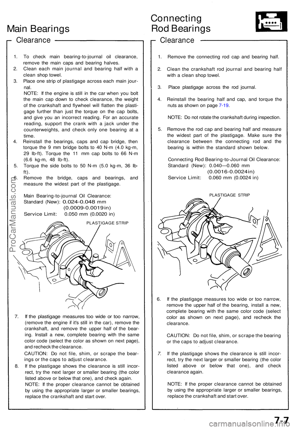
Main Bearing s
Clearanc e
1. T o chec k mai n bearing-to-journa l oi l clearance ,
remov e th e mai n cap s an d bearin g halves .
2 . Clea n eac h mai n journa l an d bearin g hal f wit h a
clea n sho p towel.
3 . Plac e on e stri p o f plastigag e acros s eac h mai n jour -
nal.
NOTE : I f th e engine is stil l i n th e ca r whe n yo u bol t
th e mai n ca p dow n t o chec k clearance , th e weigh t
o f th e crankshaf t an d flywhee l wil l flatte n th e plasti -
gag e furthe r tha n jus t th e torqu e o n th e ca p bolts ,
an d giv e yo u a n incorrec t reading . Fo r a n accurat e
reading , suppor t th e cran k wit h a jac k unde r th e
counterweights , an d chec k onl y on e bearin g a t a
time .
4. Reinstal l th e bearings , cap s an d ca p bridge , the n
torqu e th e 9 m m bridg e bolt s t o 4 0 N- m (4. 0 kg-m ,
2 9 Ib-ft) . Torqu e th e 1 1 m m ca p bolt s t o 6 6 N- m
(6. 6 kg-m , 4 8 Ib-ft) .
5 . Torqu e th e sid e bolt s t o 5 0 N- m (5. 0 kg-m , 3 6 Ib -
ft).
6. Remov e th e bridge , cap s an d bearings , an d
measur e th e wides t par t o f th e plastigage .
Mai n Bearing-to-journa l Oi l Clearance :
Standar d
(New): 0.024-0.04 8 mm
(0.0009-0.001 9 in )
Servic e Limit : 0.05 0 m m (0.002 0 in )
PLASTIGAG E STRI P
7. I f th e plastigag e measure s to o wid e o r to o narrow ,
(remove th e engine if it' s stil l i n th e car) , remov e th e
crankshaft , an d remov e th e uppe r hal f o f th e bear -
ing . Instal l a new , complet e bearin g wit h th e sam e
colo r cod e (selec t th e colo r a s show n o n nex t page) ,
an d rechec k th e clearance .
CAUTION : D o no t file , shim , o r scrap e th e bear -
ing s o r th e cap s t o adjus t clearance .
8 . I f th e plastigag e show s th e clearanc e i s stil l incor -
rect , tr y th e nex t large r o r smalle r bearin g (th e colo r
liste d abov e o r belo w tha t one) , an d chec k again .
NOTE : I f th e prope r clearanc e canno t b e obtaine d
b y usin g th e appropriat e large r o r smalle r bearings ,
replac e th e crankshaf t an d star t over .
Connectin g
Rod Bearing s
Clearanc e
1. Remov e th e connectin g ro d ca p an d bearin g half .
2 . Clea n th e crankshaf t ro d journa l an d bearin g hal f
wit h a clea n sho p towel .
3 . Plac e plastigag e acros s th e ro d journal .
4 . Reinstal l th e bearin g hal f an d cap , an d torqu e th e
nut s a s show n o n pag e 7-19 .
NOTE : D o no t rotat e th e crankshaft during inspection .
5 . Remov e th e ro d ca p an d bearin g hal f an d measur e
th e wides t par t o f th e plastigage . Mak e sur e th e
clearanc e betwee n th e connectin g ro d an d th e
bearin g i s withi n th e standar d show n below .
Connectin g Ro d Bearing-to-Journa l Oi l Clearance :
Standar d (New) : 0.040—0.06 0 m m
(0.0016-0.002 4 in )
Servic e Limit : 0.06 0 m m (0.002 4 in )
PLASTIGAG E STRI P
6. I f th e plastigag e measure s to o wid e o r to o narrow ,
remov e th e uppe r hal f of the bearing , instal l a new ,
complet e bearin g wit h th e sam e colo r cod e (selec t
color a s show n o n nex t page) , an d rechec k th e
clearance .
CAUTION: D o no t file , shim , o r scrap e th e bearin g
o r th e cap s t o adjus t clearance .
7. I f th e plastigag e show s th e clearanc e i s stil l incor -
rect , tr y th e nex t large r o r smalle r bearin g (th e colo r
liste d abov e o r belo w tha t one) , an d chec k
clearanc e again .
NOTE : I f th e prope r clearanc e canno t b e obtaine d
b y usin g th e appropriat e large r o r smalle r bearings ,
replac e th e crankshaf t an d star t over .
ProCarManuals.com
Page 132 of 1640
Main Bearings
Selection
CAUTION: If the codes are indecipherable because of
an accumulation of dirt and dust, do not scrub them
with a wire brush or scraper. Clean them only with sol-
vent or detergent.
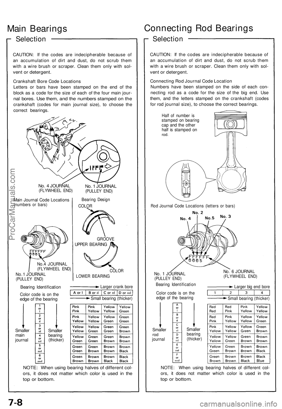
Crankshaft Bore Code Locations
Letters or bars have been stamped on the end of the
block as a code for the size of each of the four main jour-
nal bores. Use them, and the numbers stamped on the
crankshaft (codes for main journal size), to choose the
correct bearings.
No. 4 JOURNAL
(FLYWHEEL END)
Main Journal Code Locations
(numbers or bars)
No.4 JOURNAL
(FLYWHEEL END)
No. 1 JOURNAL
(PULLEY END)
No. 1 JOURNAL
(PULLEY END)
Bearing Design
COLOR
GROOVE
UPPER BEARING
COLOR
LOWER BEARING
Bearing Identification
Color code is on the
edge of the bearing
Larger crank bore
Small bearing (thicker)
Smaller
main
journal
Smaller
bearing
(thicker)
NOTE: When using bearing halves of different col-
ors, it does not matter which color is used in the
top or bottom.
Connecting Rod Bearings
Selection
CAUTION: If the codes are indecipherable because of
an accumulation of dirt and dust, do not scrub them
with a wire brush or scraper. Clean them only with sol-
vent or detergent.
Connecting Rod Journal Code Location
Numbers have been stamped on the side of each con-
necting rod as a code for the size of the big end. Use
them, and the letters stamped on the crankshaft (codes
for rod journal size), to choose the correct bearings.
Half of number is
stamped on bearing
cap and the other
half is stamped on
rod.
No. 1 JOURNAL
(PULLEY END)
Bearing Identification
Color code is on the
edge of the bearing
No. 6 JOURNAL
(FLYWHEEL END)
Larger big end bore
Small bearing (thicker)
Smaller
rod
journal
Smaller
bearing
(thicker)
NOTE: When using bearing halves of different col-
ors, it does not matter which color is used in the
top or bottom.
Rod Journal Code Locations (letters or bars)ProCarManuals.com
Page 133 of 1640
Piston/Connecting Rod Assemblies and Crankshaft
Removal
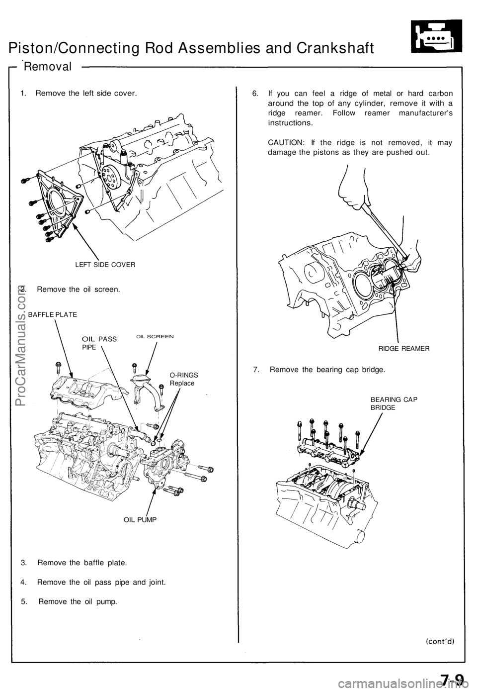
1. Remov e th e lef t sid e cover .
LEFT SID E COVE R
2. Remov e th e oi l screen .
BAFFLE PLAT E
OIL PAS S OI L SCREEN
PIPE
O-RING SReplace
OIL PUM P
3. Remov e th e baffl e plate .
4 . Remov e th e oi l pas s pip e an d joint .
5 . Remov e th e oi l pump . 6
. I f yo u ca n fee l a ridg e o f meta l o r har d carbo n
around th e to p o f an y cylinder , remov e i t wit h a
ridg e reamer . Follo w reame r manufacturer' s
instructions.
CAUTION: I f th e ridg e i s no t removed , i t ma y
damag e th e piston s a s the y ar e pushe d out .
RIDG E REAME R
7. Remov e th e bearin g ca p bridge .
BEARIN G CA PBRIDG E
ProCarManuals.com
Page 134 of 1640
Piston/Connecting Rod Assemblies and Crankshaft
Removal
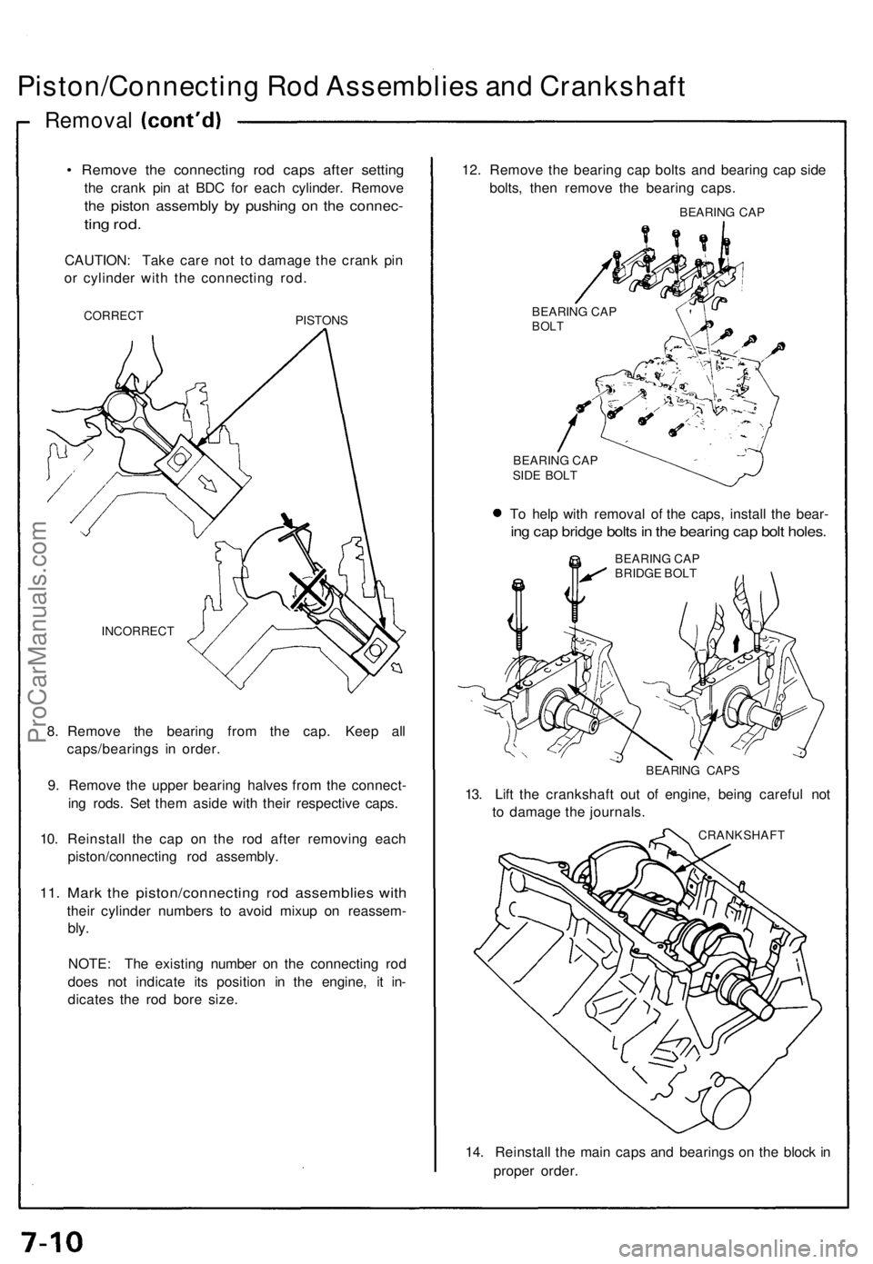
• Remove the connecting rod caps after setting
the crank pin at BDC for each cylinder. Remove
the piston assembly by pushing on the connec-
ting rod.
CAUTION: Take care not to damage the crank pin
or cylinder with the connecting rod.
CORRECT
PISTONS
INCORRECT
8. Remove the bearing from the cap. Keep all
caps/bearings in order.
9. Remove the upper bearing halves from the connect-
ing rods. Set them aside with their respective caps.
10. Reinstall the cap on the rod after removing each
piston/connecting rod assembly.
11. Mark the piston/connecting rod assemblies with
their cylinder numbers to avoid mixup on reassem-
bly.
NOTE: The existing number on the connecting rod
does not indicate its position in the engine, it in-
dicates the rod bore size.
12. Remove the bearing cap bolts and bearing cap side
bolts, then remove the bearing caps.
BEARING CAP
BEARING CAP
BOLT
BEARING CAP
SIDE BOLT
To help with removal of the caps, install the bear-
ing cap bridge bolts in the bearing cap bolt holes.
BEARING CAP
BRIDGE BOLT
BEARING CAPS
13. Lift the crankshaft out of engine, being careful not
to damage the journals.
CRANKSHAFT
14. Reinstall the main caps and bearings on the block in
proper order.ProCarManuals.com
Page 135 of 1640
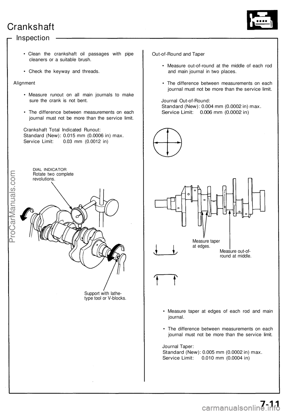
Crankshaft
Inspection
• Clea n th e crankshaf t oi l passage s wit h pip e
cleaner s o r a suitabl e brush .
• Chec k th e keywa y an d threads .
Alignmen t
• Measur e runou t o n al l mai n journal s t o mak e
sur e th e cran k i s no t bent .
• Th e differenc e betwee n measurement s o n eac h
journa l mus t no t b e mor e tha n th e servic e limit .
Crankshaf t Tota l Indicate d Runout :
Standard (New) : 0.01 5 m m (0.000 6 in ) max .
Servic e Limit : 0.0 3 m m (0.001 2 in )
DIA L INDICATO RRotate tw o complet erevolutions .
Support wit h lathe -type too l o r V-blocks .
Out-of-Roun d an d Tape r
• Measur e out-of-roun d a t th e middl e o f eac h ro d
an d mai n journa l i n tw o places .
• Th e differenc e betwee n measurement s o n eac h
journa l mus t no t b e mor e tha n th e servic e limit .
Journa l Out-of-Round :
Standard (New) : 0.00 4 m m (0.000 2 in ) max .
Servic e Limit : 0.00 6 m m (0.000 2 in )
Measur e tape rat edges .Measur e out-of -round a t middle .
• Measur e tape r a t edge s o f eac h ro d an d mai n
journal .
• Th e differenc e betwee n measurement s o n eac h
journa l mus t no t b e mor e tha n th e servic e limit .
Journa l Taper :
Standar d (New) : 0.00 5 m m (0.000 2 in ) max .
Servic e Limit : 0.01 0 m m (0.000 4 in )
ProCarManuals.com
Page 136 of 1640
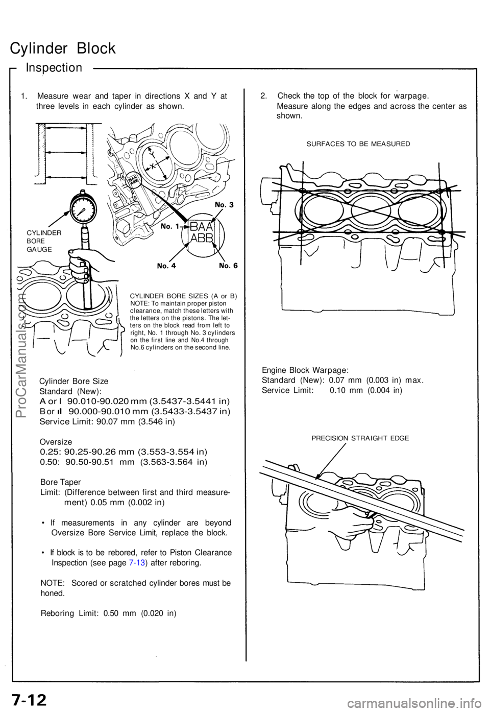
Cylinder Bloc k
Inspectio n
1. Measur e wea r an d tape r i n direction s X an d Y at
thre e level s i n eac h cylinde r a s shown .
CYLINDE R BOR E SIZE S ( A o r B )NOTE : T o maintai n prope r pisto n
clearance , matc h thes e letter s wit h
th e letter s o n th e pistons . Th e let -
ters o n th e bloc k rea d fro m lef t t oright , No . 1 throug h No . 3 cylinder son th e firs t lin e an d No. 4 throug hNo.6 cylinder s o n th e secon d line .
Cylinde r Bor e Siz e
Standar d (New) :
A o r I 90.010-90.02 0 m m (3.5437-3.544 1 in )
B or 90.000-90.01 0 m m (3.5433-3.543 7 in )
Servic e Limit : 90.0 7 m m (3.54 6 in )
Oversiz e
0.25: 90.25-90.2 6 m m (3.553-3.55 4 in )
0.50 : 90.50-90.5 1 m m (3.563-3.56 4 in )
Bor e Tape r
Limit : (Differenc e betwee n firs t an d thir d measure -
ment) 0.0 5 m m (0.00 2 in )
• I f measurement s i n an y cylinde r ar e beyon d
Oversiz e Bor e Servic e Limit , replac e th e block .
• I f bloc k i s t o b e rebored , refe r t o Pisto n Clearanc e
Inspectio n (se e pag e 7-13 ) afte r reboring .
NOTE : Score d o r scratche d cylinde r bore s mus t b e
honed .
Reborin g Limit : 0.5 0 m m (0.02 0 in ) 2
. Chec k th e to p o f th e bloc k fo r warpage .
Measur e alon g th e edge s an d acros s th e cente r a s
shown .
SURFACE S T O B E MEASURE D
Engine Bloc k Warpage :
Standar d (New) : 0.0 7 m m (0.00 3 in ) max .
Servic e Limit : 0.1 0 m m (0.00 4 in )
PRECISIO N STRAIGH T EDG E
CYLINDE RBOREGAUG E
ProCarManuals.com
Page 137 of 1640
Piston/Connecting Rod
Assemblies
Inspection
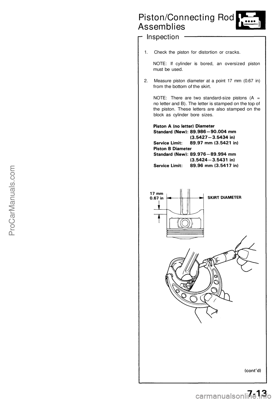
1. Check the piston for distortion or cracks.
NOTE: If cylinder is bored, an oversized piston
must be used.
2. Measure piston diameter at a point 17 mm (0.67 in)
from the bottom of the skirt.
NOTE: There are two standard-size pistons (A =
no letter and B). The letter is stamped on the top of
the piston. These letters are also stamped on the
block as cylinder bore sizes.ProCarManuals.com
Page 138 of 1640
Piston/Connecting Ro d
Assemblie s
Inspection
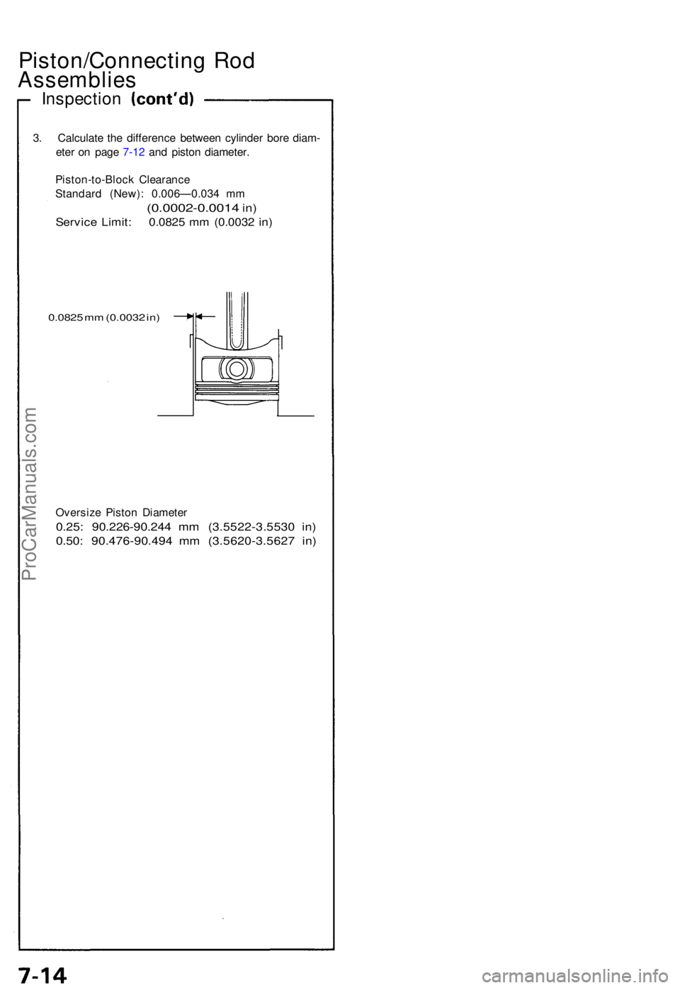
3. Calculat e th e differenc e betwee n cylinde r bor e diam -
ete r o n pag e 7-1 2 an d pisto n diameter .
Piston-to-Bloc k Clearanc e
Standar d (New) : 0.006—0.03 4 m m
(0.0002-0.001 4 in)
Servic e Limit : 0.082 5 m m (0.003 2 in )
0.082 5 m m (0.003 2 in )
Oversiz e Pisto n Diamete r
0.25: 90.226-90.24 4 m m (3.5522-3.553 0 in )
0.50 : 90.476-90.49 4 m m (3.5620-3.562 7 in )
ProCarManuals.com
Page 139 of 1640
Connecting Rod s
Selectio n
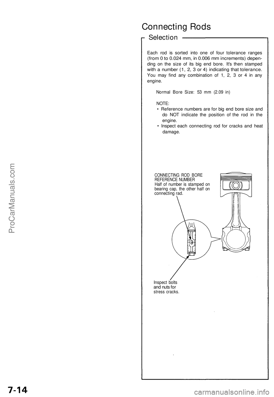
Each ro d i s sorte d int o on e o f fou r toleranc e range s
(from 0 to 0.02 4 mm , i n 0.00 6 m m increments ) depen -
ding o n th e siz e o f it s bi g en d bore . It' s the n stampe d
with a numbe r (1 , 2 , 3 or 4 ) indicatin g tha t tolerance .
You ma y fin d an y combinatio n o f 1 , 2 , 3 or 4 in an y
engine .
Norma l Bor e Size : 5 3 m m (2.0 9 in )
NOTE :
• Referenc e number s ar e fo r bi g en d bor e siz e an d
d o NO T indicat e th e positio n of the ro d i n th e
engine .
• Inspec t eac h connectin g ro d fo r crack s an d hea t
damage .
CONNECTIN G RO D BOR EREFERENC E NUMBE RHalf o f numbe r i s stampe d o nbearin g cap , th e othe r hal f o nconnectin g rad .
Inspec t bolt sand nut s fo rstres s cracks .
ProCarManuals.com
Page 140 of 1640
Piston Ring s
End Ga p
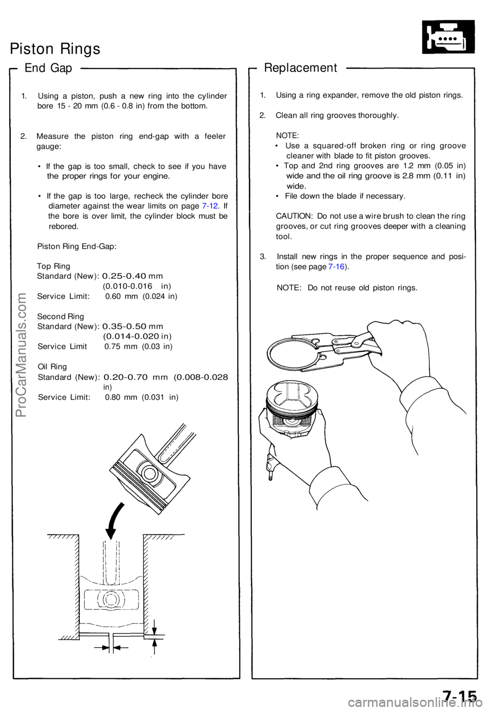
1. Usin g a piston , pus h a ne w rin g int o th e cylinde r
bor e 1 5 - 2 0 m m (0. 6 - 0. 8 in ) fro m th e bottom .
2 . Measur e th e pisto n rin g end-ga p wit h a feele r
gauge :
• I f th e ga p i s to o small , chec k t o se e i f yo u hav e
the prope r ring s fo r you r engine .
• I f th e ga p i s to o large , rechec k th e cylinde r bor e
diameter against th e wea r limit s o n pag e 7-12 . I f
th e bor e i s ove r limit , th e cylinde r bloc k mus t b e
rebored .
Pisto n Rin g End-Gap :
To p Rin g
Standar d (New) :
0.25-0.4 0 mm
(0.010-0.01 6 in )
Servic e Limit : 0.6 0 m m (0.02 4 in )
Secon d Rin g
Standar d (New) :
0.35-0.5 0 mm
(0.014-0.02 0 in)
Servic e Limi t 0.7 5 m m (0.0 3 in )
Oi l Rin g
Standar d (New) :
0.20-0.7 0 mm (0.008-0.02 8
in)
Servic e Limit : 0.8 0 m m (0.03 1 in )
Replacemen t
1. Usin g a rin g expander , remov e th e ol d pisto n rings .
2 . Clea n al l rin g groove s thoroughly .
NOTE:
• Us e a squared-of f broke n rin g o r rin g groov e
cleane r wit h blad e t o fi t pisto n grooves .
• To p an d 2n d rin g groove s ar e 1. 2 m m (0.0 5 in )
wid e an d th e oi l rin g groov e is 2. 8 m m (0.1 1 in )
wide .
• Fil e dow n th e blad e i f necessary .
CAUTION : D o no t us e a wir e brus h to clea n th e rin g
grooves , o r cu t rin g groove s deepe r wit h a cleanin g
tool .
3 . Instal l ne w ring s i n th e prope r sequenc e an d posi -
tio n (se e pag e 7-16 ).
NOTE : D o no t reus e ol d pisto n rings .
ProCarManuals.com