ACURA NSX 1991 Service Repair Manual
Manufacturer: ACURA, Model Year: 1991, Model line: NSX, Model: ACURA NSX 1991Pages: 1640, PDF Size: 60.48 MB
Page 161 of 1640
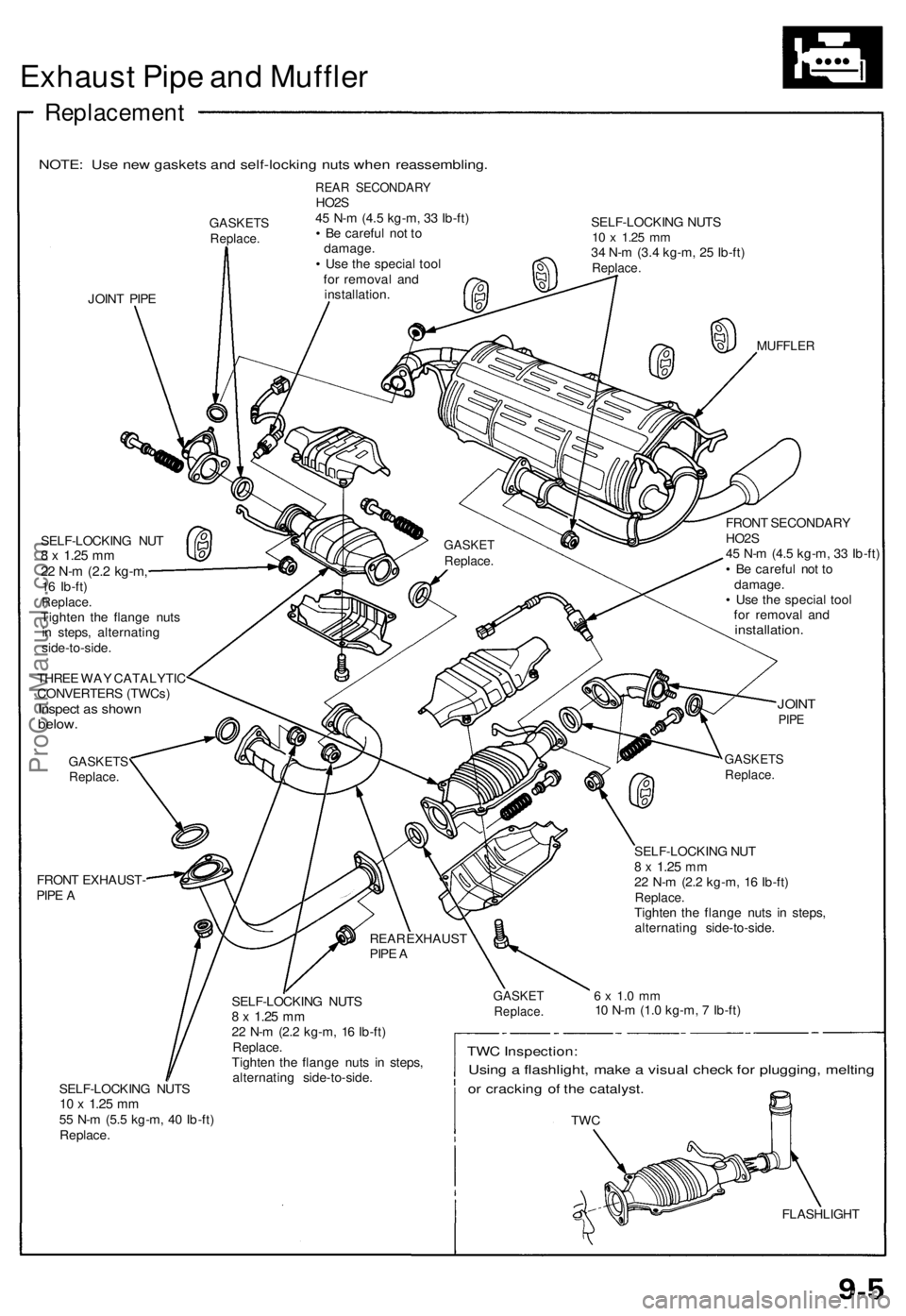
Exhaust Pip e an d Muffle r
Replacemen t
NOTE: Us e ne w gasket s an d self-lockin g nut s whe n reassembling .
GASKETSReplace.
JOINT PIP E
REA R SECONDAR YHO2S
4 5 N- m (4. 5 kg-m , 3 3 Ib-ft )
• B e carefu l no t t o
damage .
• Us e th e specia l too l
fo r remova l an d
installation . SELF-LOCKIN
G NUT S
10 x 1.2 5 mm34 N- m (3. 4 kg-m , 2 5 Ib-ft )Replace .
MUFFLE R
SELF-LOCKIN G NU T8 x 1.2 5 mm22 N- m (2. 2 kg-m ,16 Ib-ft )Replace .Tighten th e flang e nut s
i n steps , alternatin g
side-to-side .
THRE E WA Y CATALYTI C
CONVERTER S (TWCs )
Inspect a s show nbelow.
GASKET SReplace.
FRONT EXHAUST -
PIP E A FRON
T SECONDAR Y
HO2 S
4 5 N- m (4. 5 kg-m , 3 3 Ib-ft )
• B e carefu l no t t o
damage .
• Us e th e specia l too l
fo r remova l an d
installation .
JOINTPIPE
SELF-LOCKIN G NUT S10 x 1.2 5 mm55 N- m (5. 5 kg-m , 4 0 Ib-ft )
Replace . SELF-LOCKIN
G NUT S
8 x 1.2 5 mm22 N- m (2. 2 kg-m , 1 6 Ib-ft )Replace .Tighten th e flang e nut s i n steps ,
alternatin g side-to-side .
GASKETSReplace.
SELF-LOCKIN G NU T8 x 1.2 5 mm22 N- m (2. 2 kg-m , 1 6 Ib-ft )Replace .Tighten th e flang e nut s i n steps ,
alternatin g side-to-side .
6 x 1. 0 m m10 N- m (1. 0 kg-m , 7 Ib-ft )
TWC Inspection :
Using a flashlight , mak e a visua l chec k fo r plugging , meltin g
or crackin g o f th e catalyst .
TWC
FLASHLIGH T
REA
R EXHAUS T
PIP E A
GASKE TReplace .
GASKETReplace .
ProCarManuals.com
Page 162 of 1640
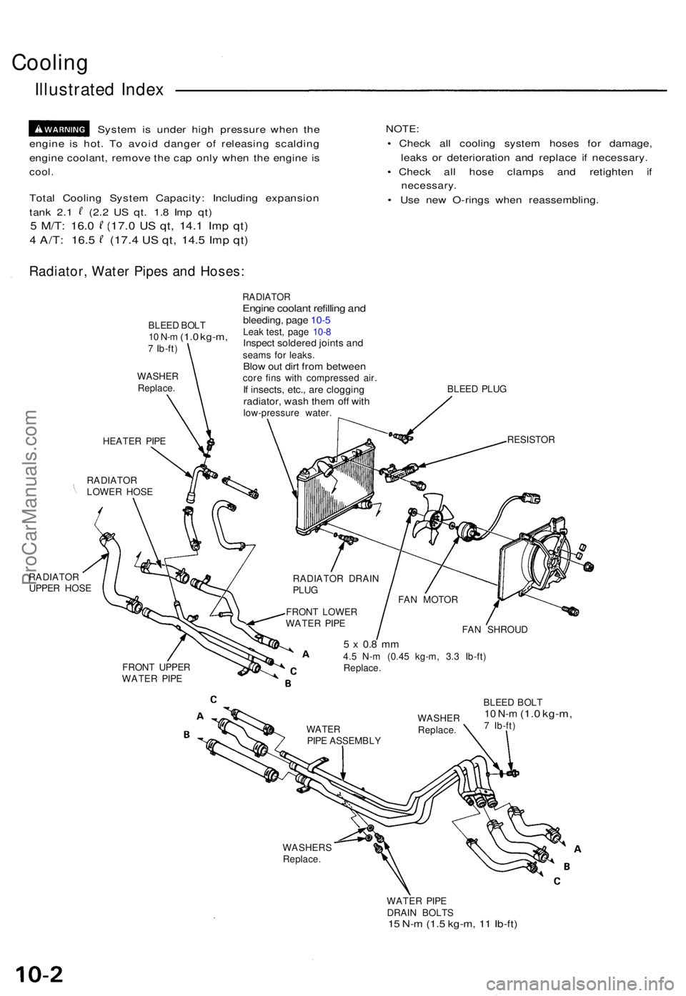
Cooling
Illustrated Index
Syste m is unde r hig h pressur e whe n th e
engin e i s hot . T o avoi d dange r o f releasin g scaldin g
engin e coolant , remov e th e ca p onl y whe n th e engin e i s
cool .
Tota l Coolin g Syste m Capacity : Includin g expansio n
tank 2. 1 (2. 2 U S qt . 1. 8 Im p qt )
5 M/T : 16. 0 (17. 0 US qt , 14. 1 Imp qt )
4 A/T : 16. 5 (17. 4 US qt , 14. 5 Imp qt )
NOTE :
• Chec k al l coolin g syste m hose s fo r damage ,
leak s o r deterioratio n an d replac e i f necessary .
• Chec k al l hos e clamp s an d retighte n i f
necessary .
• Us e ne w O-ring s whe n reassembling .
Radiator, Wate r Pipe s an d Hoses :
BLEED BOL T10 N- m (1. 0 kg-m ,7 Ib-ft )
WASHE RReplace .
HEATER PIP E
RADIATO R
LOWE R HOS E
RADIATO R
UPPE R HOS E
RADIATO REngine coolan t refillin g an dbleeding , pag e 10- 5Leak test , pag e 10- 8Inspec t soldere d joint s an dseam s fo r leaks .Blow ou t dir t fro m betwee ncore fin s wit h compresse d air .If insects , etc. , ar e cloggin gradiator, was h the m of f wit hlow-pressur e water . BLEE
D PLU G
RESISTO R
RADIATO R DRAI N
PLU G
FRON T LOWE R
WATE R PIP E
FRON T UPPE R
WATE R PIP E FA
N SHROU D
5 x 0. 8 m m4.5 N- m (0.4 5 kg-m , 3. 3 Ib-ft )
Replace .
BLEED BOL T
10 N- m (1. 0 kg-m ,7 Ib-ft )
WASHER S
Replace .
WATER PIP E
DRAI N BOLT S
15 N- m (1. 5 kg-m , 1 1 Ib-ft )
WATE RPIPE ASSEMBL YWASHE
RReplace .
FAN MOTO R
ProCarManuals.com
Page 163 of 1640
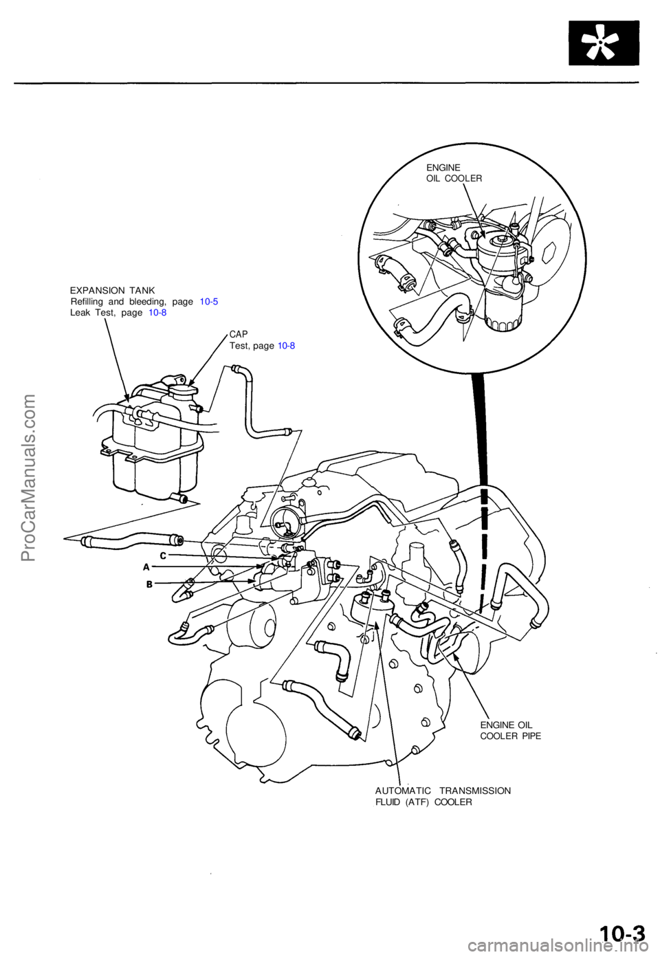
EXPANSION TAN K
Refillin g an d bleeding , pag e 10- 5
Lea k Test , pag e 10- 8
ENGINE OI L
COOLE R PIP E
AUTOMATI C TRANSMISSIO N
FLUI D (ATF ) COOLE R
ENGINEOIL COOLE R
CAPTest , pag e 10- 8
ProCarManuals.com
Page 164 of 1640
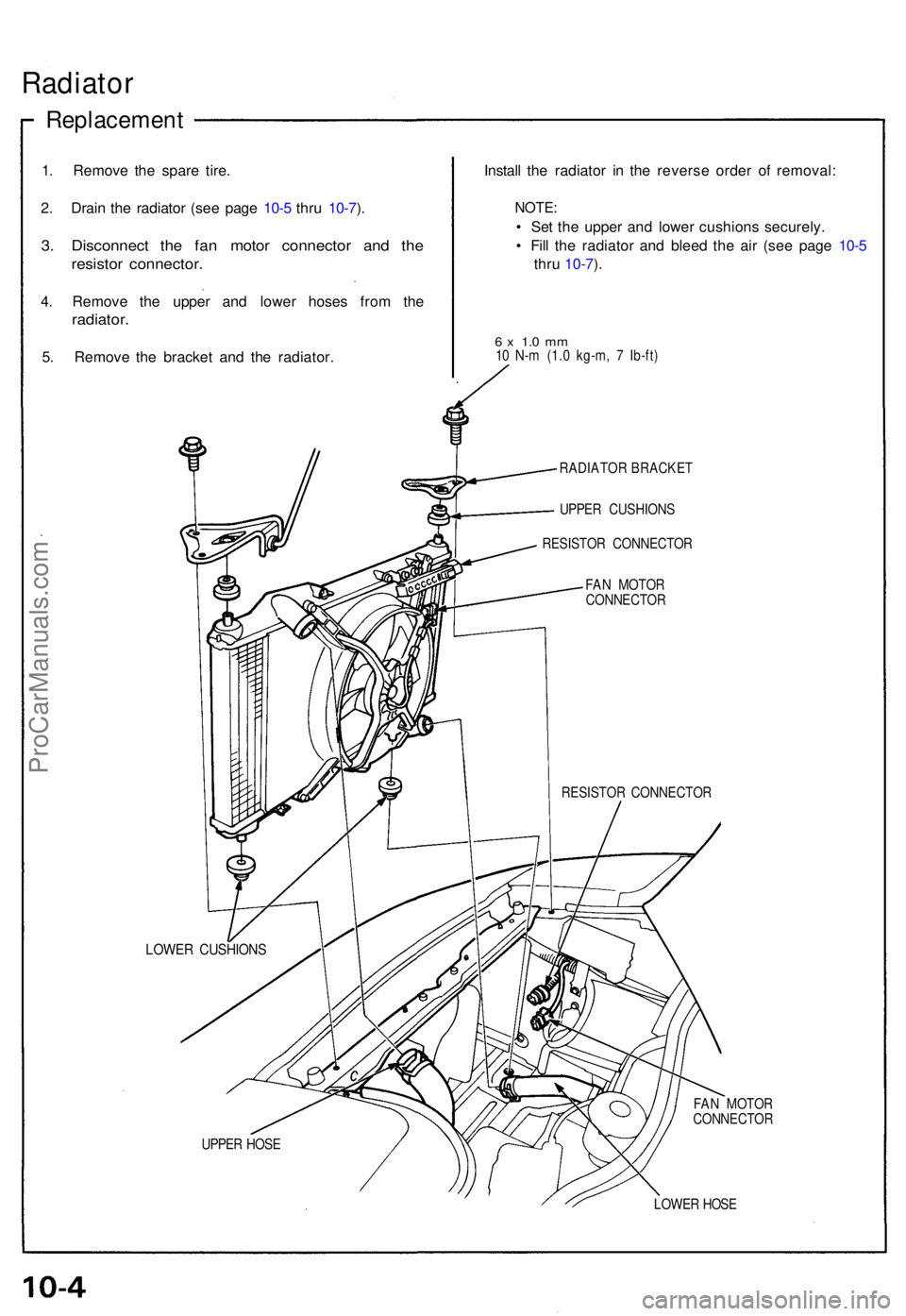
Radiator
Replacemen t
1. Remov e th e spar e tire .
2 . Drai n th e radiato r (se e pag e 10- 5 thr u 10-7 ).
3 . Disconnec t th e fa n moto r connecto r an d th e
resisto r connector .
4. Remov e th e uppe r an d lowe r hose s fro m th e
radiator .
5. Remov e th e bracke t an d th e radiator . Instal
l th e radiato r i n th e revers e orde r o f removal :
NOTE:
• Se t th e uppe r an d lowe r cushion s securely .
• Fil l th e radiato r an d blee d th e ai r (se e pag e 10- 5
thr u 10-7 ).
6 x 1. 0 m m10 N- m (1. 0 kg-m , 7 Ib-ft )
RADIATO R BRACKE T
UPPE R CUSHION S
RESISTO R CONNECTO R
FA N MOTO R
CONNECTO R
RESISTO R CONNECTO R
LOWER CUSHION S
FAN MOTO R
CONNECTO R
UPPE R HOS E
LOWER HOS E
ProCarManuals.com
Page 165 of 1640
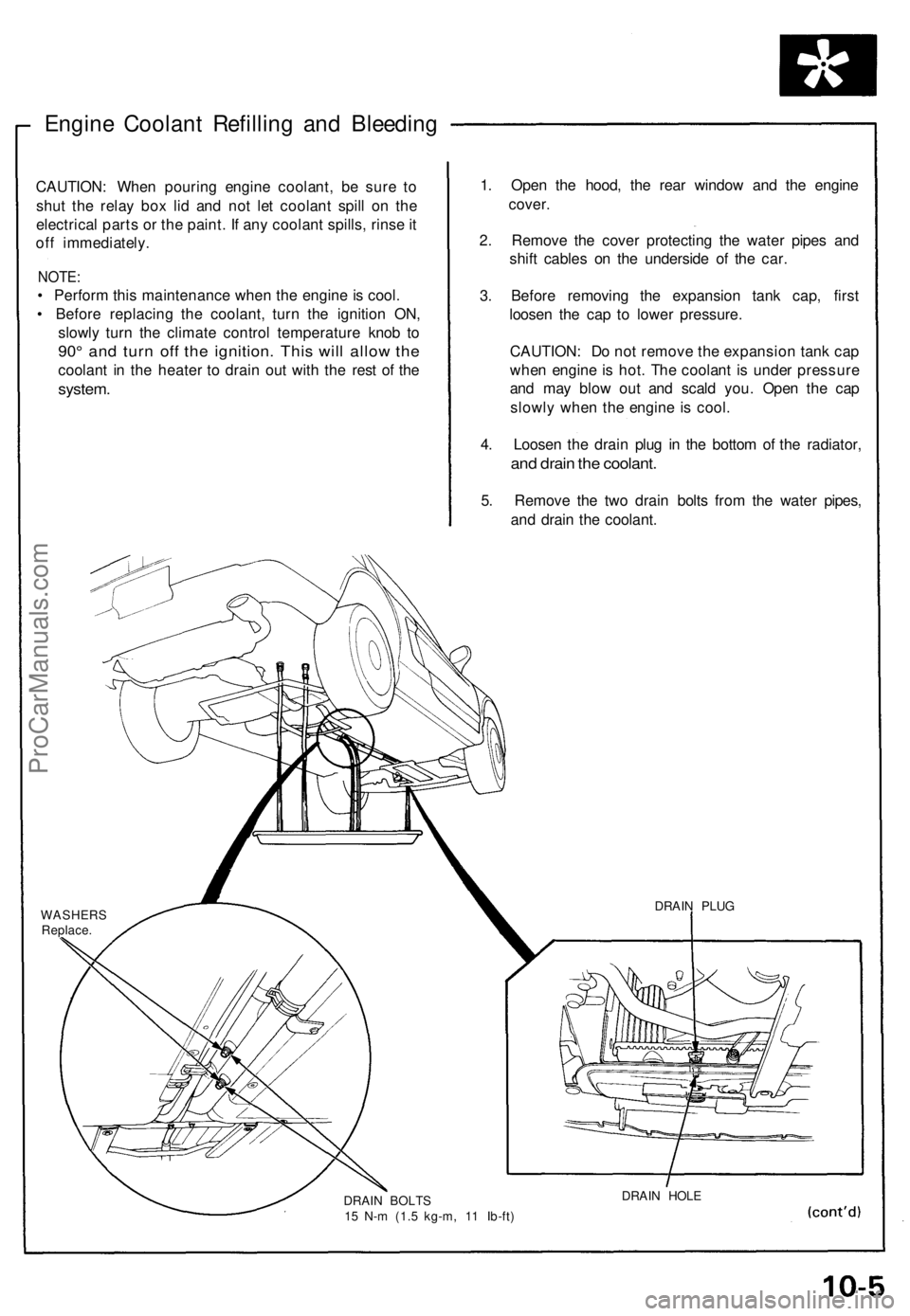
Engine Coolant Refilling and Bleeding
CAUTION: When pouring engine coolant, be sure to
shut the relay box lid and not let coolant spill on the
electrical parts or the paint. If any coolant spills, rinse it
off immediately.
NOTE:
• Perform this maintenance when the engine is cool.
• Before replacing the coolant, turn the ignition ON,
slowly turn the climate control temperature knob to
90° and turn off the ignition. This will allow the
coolant in the heater to drain out with the rest of the
system.
1. Open the hood, the rear window and the engine
cover.
2. Remove the cover protecting the water pipes and
shift cables on the underside of the car.
3. Before removing the expansion tank cap, first
loosen the cap to lower pressure.
CAUTION: Do not remove the expansion tank cap
when engine is hot. The coolant is under pressure
and may blow out and scald you. Open the cap
slowly when the engine is cool.
4. Loosen the drain plug in the bottom of the radiator,
and drain the coolant.
5. Remove the two drain bolts from the water pipes,
and drain the coolant.
WASHERS
Replace.
DRAIN BOLTS
15 N-m (1.5 kg-m, 11 Ib-ft)
DRAIN HOLE
DRAIN PLUGProCarManuals.com
Page 166 of 1640
Radiator
Engine Coolan t Refillin g an d Bleedin g
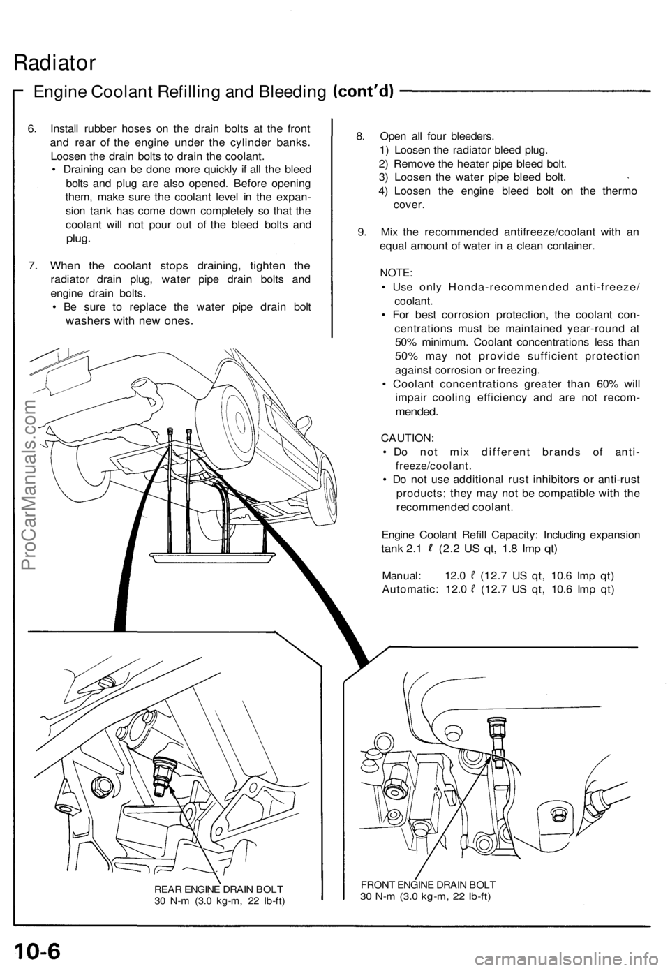
6. Instal l rubbe r hose s o n th e drai n bolt s a t th e fron t
an d rea r of the engin e unde r th e cylinde r banks .
Loose n th e drai n bolt s t o drai n th e coolant .
• Drainin g ca n b e don e mor e quickl y i f al l th e blee d
bolt s an d plu g ar e als o opened . Befor e openin g
them , mak e sur e th e coolan t leve l i n th e expan -
sio n tan k ha s com e dow n completel y s o tha t th e
coolan t wil l no t pou r ou t o f th e blee d bolt s an d
plug .
7. Whe n th e coolan t stop s draining , tighte n th e
radiato r drai n plug , wate r pip e drai n bolt s an d
engin e drai n bolts .
• B e sur e t o replac e th e wate r pip e drai n bol t
washer s wit h ne w ones .
REAR ENGIN E DRAI N BOL T
3 0 N- m (3. 0 kg-m , 2 2 Ib-ft )
8. Ope n al l fou r bleeders .
1 ) Loose n th e radiato r blee d plug .
2 ) Remov e th e heate r pip e blee d bolt .
3 ) Loose n th e wate r pip e blee d bolt .
4 ) Loose n th e engin e blee d bol t o n th e therm o
cover.
9. Mi x th e recommende d antifreeze/coolan t wit h a n
equa l amoun t o f wate r i n a clea n container .
NOTE:
• Us e onl y Honda-recommende d anti-freeze /
coolant.
• Fo r bes t corrosio n protection , th e coolan t con -
centration s mus t b e maintaine d year-roun d a t
50 % minimum . Coolan t concentration s les s tha n
50 % ma y no t provid e sufficien t protectio n
agains t corrosio n o r freezing .
• Coolan t concentration s greate r tha n 60 % wil l
impai r coolin g efficienc y an d ar e no t recom -
mended.
CAUTION :
• D o no t mi x differen t brand s o f anti -
freeze/coolant .
• D o no t us e additiona l rus t inhibitor s o r anti-rus t
products ; the y ma y no t b e compatibl e wit h th e
recommende d coolant .
Engin e Coolan t Refil l Capacity : Includin g expansio n
tank 2. 1 (2. 2 U S qt , 1. 8 Im p qt )
Manual : 12. 0 (12. 7 U S qt , 10. 6 Im p qt )
Automatic : 12. 0 (12. 7 U S qt , 10. 6 Im p qt )
FRON T ENGIN E DRAI N BOL T30 N- m (3. 0 kg-m , 2 2 Ib-ft )
ProCarManuals.com
Page 167 of 1640
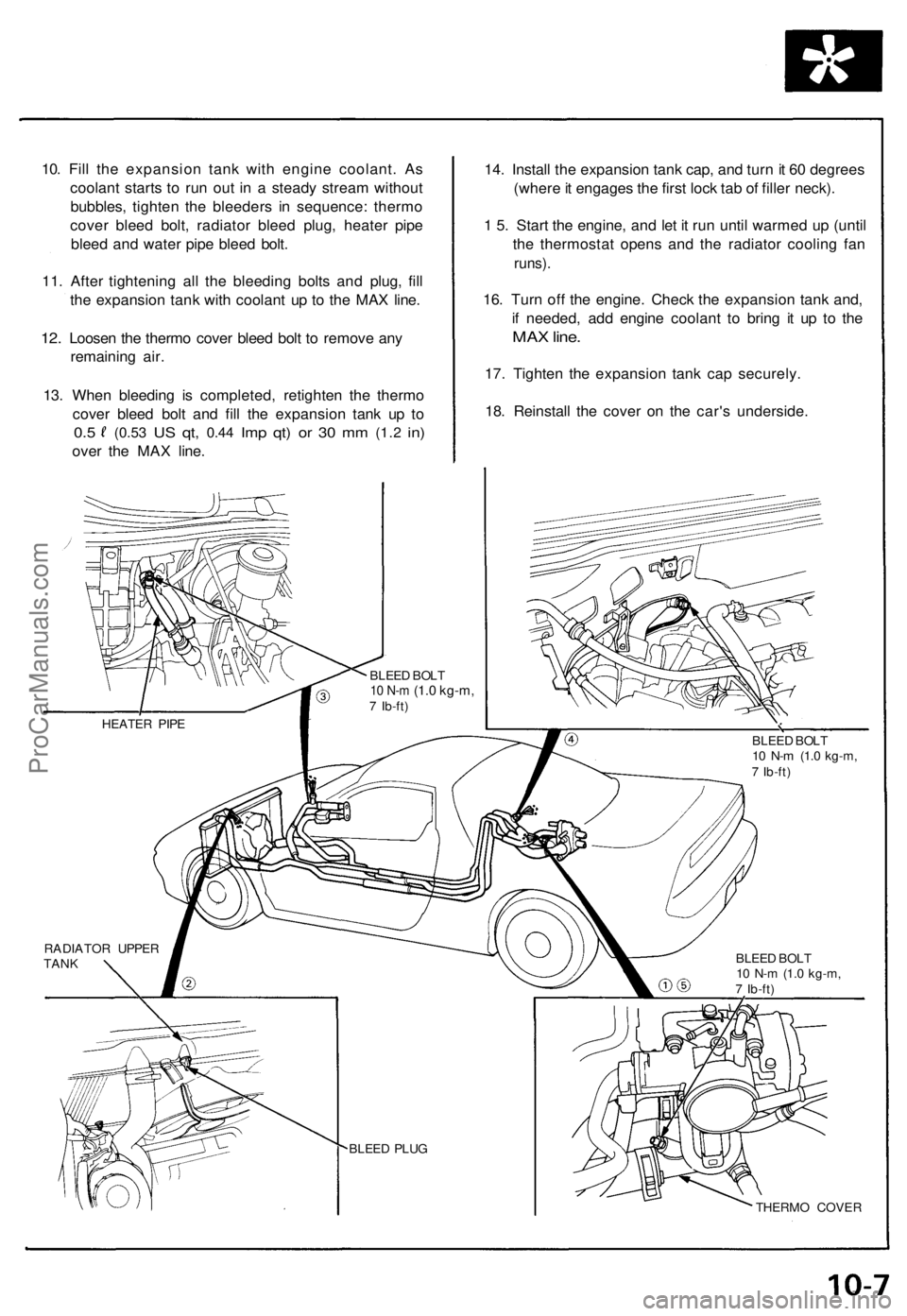
10. Fil l th e expansio n tan k wit h engin e coolant . A s
coolan t start s t o ru n ou t i n a stead y strea m withou t
bubbles , tighte n th e bleeder s i n sequence : therm o
cove r blee d bolt , radiato r blee d plug , heate r pip e
blee d an d wate r pip e blee d bolt .
11 . Afte r tightenin g al l th e bleedin g bolt s an d plug , fil l
th e expansio n tan k wit h coolan t u p t o th e MA X line .
12. Loose n th e therm o cove r blee d bol t t o remov e an y
remainin g air .
13 . Whe n bleedin g i s completed , retighte n th e therm o
cove r blee d bol t an d fill the expansio n tan k u p t o
0. 5 (0.5 3 US qt , 0.4 4 Imp qt ) o r 3 0 m m (1. 2 in)
ove r th e MA X line . 14
. Instal l th e expansio n tan k cap , an d tur n it 6 0 degree s
(wher e it engage s th e firs t loc k ta b o f fille r neck) .
1 5 . Star t th e engine , an d le t i t ru n unti l warme d u p (unti l
th e thermosta t open s an d th e radiato r coolin g fa n
runs) .
16. Tur n of f th e engine . Chec k th e expansio n tan k and ,
i f needed , ad d engin e coolan t t o brin g i t u p t o th e
MA X line .
17. Tighte n th e expansio n tan k ca p securely .
18 . Reinstal l th e cove r o n th e car' s underside .
THERMO COVE R
BLEE
D PLU G
RADIATO
R UPPE R
TAN K HEATE
R PIP E
BLEED BOL T
10 N- m (1. 0 kg-m ,7 Ib-ft )
BLEE
D BOL T
10 N- m (1. 0 kg-m ,7 Ib-ft )
BLEE
D BOL T
10 N- m (1. 0 kg-m ,7 Ib-ft )
ProCarManuals.com
Page 168 of 1640
Expansion Tan k
Cap Testin g
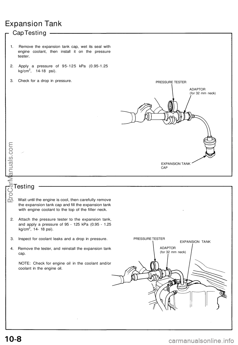
1. Remov e th e expansio n tan k cap , we t it s sea l wit h
engin e coolant , the n instal l i t o n th e pressur e
tester.
2. Appl y a pressur e o f 95-12 5 kP a (0.95-1.2 5
kg/cm2, 14-1 8 psi) .
3 . Chec k fo r a dro p i n pressure .
PRESSUR E TESTE R
ADAPTO R(for 3 2 m m neck )
EXPANSIO N TAN K
CAP
Testin g
1. Wai t unti l th e engin e is cool , the n carefull y remov e
the expansio n tan k ca p an d fil l th e expansio n tan k
with engin e coolan t t o th e to p o f th e fille r neck .
2. Attac h th e pressur e teste r t o th e expansio n tank ,
an d appl y a pressur e o f 9 5 - 12 5 kP a (0.9 5 - 1.2 5
kg/cm
2, 14 - 1 8 psi) .
3 . Inspec t fo r coolan t leak s an d a dro p i n pressure .
4 . Remov e th e tester , an d reinstal l th e expansio n tan k
cap.
NOTE : Chec k fo r engin e oi l i n th e coolan t and/o r
coolan t i n th e engin e oil .
PRESSUR E TESTE R
EXPANSION TAN K
ADAPTO R(for 3 2 m m neck )
ProCarManuals.com
Page 169 of 1640
Thermostat
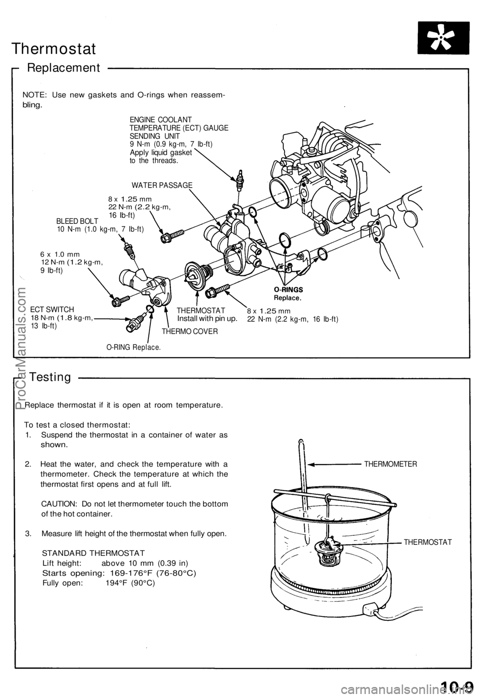
Replacemen t
NOTE: Us e ne w gasket s an d O-ring s whe n reassem -
bling.
ENGIN E COOLAN T
TEMPERATUR E (ECT ) GAUG E
SENDIN G UNI T
9 N- m (0. 9 kg-m , 7 Ib-ft )
Apply liqui d gaske tto th e threads .
WATE R PASSAG E
8 x 1.2 5 mm22 N- m (2. 2 kg-m ,16 Ib-ft )BLEE D BOL T
1 0 N- m (1. 0 kg-m , 7 Ib-ft )
6 x 1. 0 m m12 N- m (1. 2 kg-m ,9 Ib-ft )
ECT SWITC H18 N- m (1. 8 kg-m ,13 Ib-ft )
8 x 1.2 5 mm22 N- m (2. 2 kg-m , 1 6 Ib-ft )
THERM O COVE R
O-RING Replace .
Testing
Replac e thermosta t i f i t i s ope n a t roo m temperature .
T o tes t a close d thermostat :
1 . Suspen d th e thermosta t i n a containe r o f wate r a s
shown .
2. Hea t th e water , an d chec k th e temperatur e wit h a
thermometer . Chec k th e temperatur e a t whic h th e
thermosta t firs t open s an d a t ful l lift .
CAUTION : D o no t le t thermomete r touc h th e botto m
o f th e ho t container .
3 . Measur e lif t heigh t o f th e thermosta t whe n full y open .
STANDAR D THERMOSTA T
Lif t height : abov e 1 0 m m (0.3 9 in )
Start s opening : 169-176° F (76-80°C )
Fully open : 194° F (90°C )
THERMOMETE R
THERMOSTA T
THERMOSTA
T
Install wit h pi n up .
ProCarManuals.com
Page 170 of 1640
Water Pum p
Illustrate d Inde x
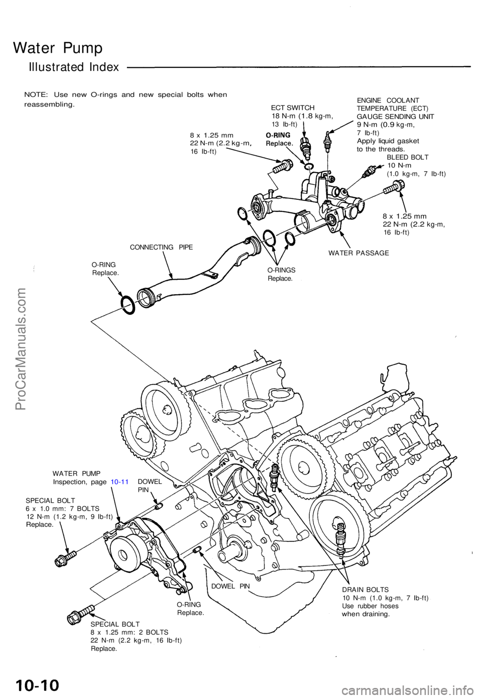
NOTE : Us e ne w O-ring s an d ne w specia l bolt s whe n
reassembling .
8 x 1.2 5 mm22 N- m (2. 2 kg- m16 Ib-ft )
ECT SWITC H18 N- m (1. 8 kg-m ,13 Ib-ft ) ENGIN
E COOLAN T
TEMPERATUR E (ECT )GAUG E SENDIN G UNI T9 N- m (0. 9 kg-m ,7 Ib-ft )Apply liqui d gaske tto th e threads .BLEED BOL T10 N- m(1.0 kg-m , 7 Ib-ft )
8 x 1.2 5 mm22 N- m (2. 2 kg-m ,16 Ib-ft )
O-RIN G
Replace .
DRAIN BOLT S
1 0 N- m (1. 0 kg-m , 7 Ib-ft )
Us e rubbe r hose s
when draining .
SPECIAL BOL T
8 x 1.2 5 mm : 2 BOLT S
2 2 N- m (2. 2 kg-m , 1 6 Ib-ft )
Replace . DOWE
L PI N
O-RIN G
Replace .
WATER PUM PInspection , pag e 10-1 1 DOWE LPIN
SPECIA L BOL T
6 x 1. 0 mm : 7 BOLT S
1 2 N- m (1. 2 kg-m , 9 Ib-ft )
Replace .
WATER PASSAG E
O-RING S
Replace .
CONNECTIN
G PIP E
ProCarManuals.com