ACURA NSX 1991 Service Repair Manual
Manufacturer: ACURA, Model Year: 1991, Model line: NSX, Model: ACURA NSX 1991Pages: 1640, PDF Size: 60.48 MB
Page 1511 of 1640
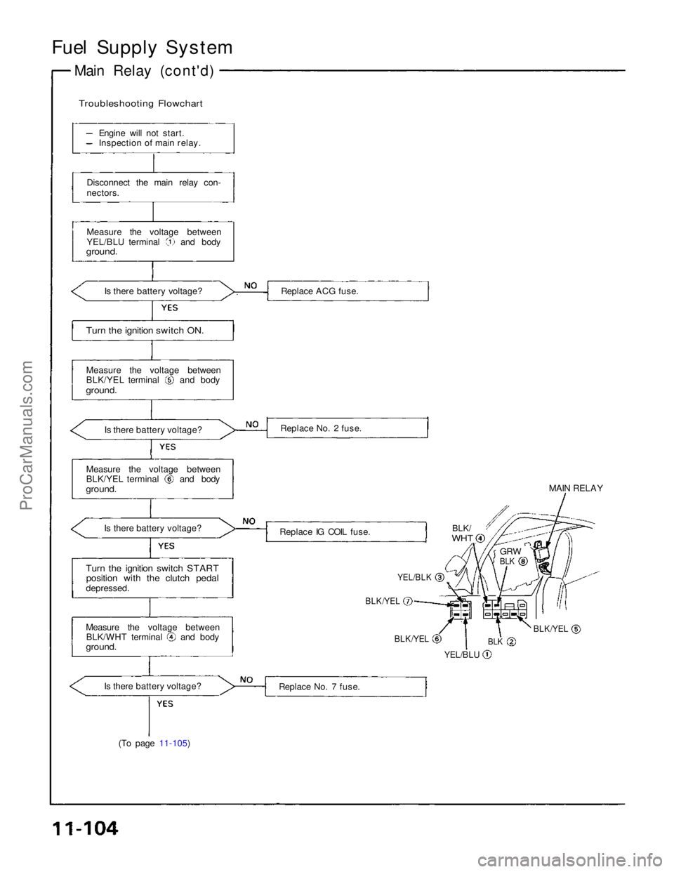
Fuel Supply System
Main Relay (cont'd)
Troubleshooting Flowchart
Engine will not start.
Inspection of main relay.
Disconnect the main relay con-
nectors.
Measure the voltage between YEL/BLU terminal and body
ground.
Is there battery voltage? Replace ACG fuse.
Turn the ignition switch ON.
Measure the voltage between BLK/YEL terminal and body
ground.
Replace No. 2 fuse.
Is there battery voltage?
Measure the voltage between BLK/YEL terminal and body
ground.
Is there battery voltage? Replace IG COIL fuse. MAIN RELAY
BLK/
WHT
GRW
BLK
YEL/BLK
BLK/YEL
BLK/YEL
YEL/BLU
BLK
BLK/YEL
Turn the ignition switch START
position with the clutch pedal
depressed.
Measure the voltage between BLK/WHT terminal and body
ground.
Is there battery voltage? Replace No. 7 fuse.
(To page 11-105)ProCarManuals.com
Page 1512 of 1640
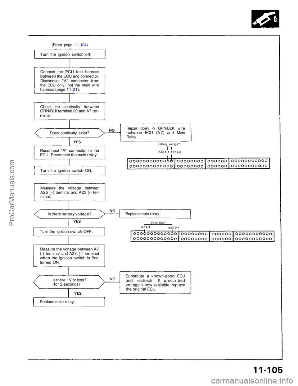
(From page 11-104)
Turn the ignition switch off.
Connect the ECU test harness
between the ECU and connector.
Disconnect "A" connector from
the ECU only, not the main wire
harness (page 11-21).
Check for continuity between GRN/BLK terminal and A7 ter-
minal.
Does continuity exist?
Repair open in GRN/BLK wire
between ECU (A7) and Main
Relay.
battety voltage?
A23
A25
Reconnect "A" connector to the
ECU. Reconnect the main relay.
Turn the ignition switch ON.
Measure the voltage between
A25 (+) terminal and A23 (-) ter-
minal.
Is there battery voltage?
Turn the ignition switch OFF.
Replace main relay.
1V or less
A7
A23
Measure the voltage between A7
(+) terminal and A23 (-) terminal
when the ignition switch is first
turned ON. Is there 1V or less?
(for 2 seconds)
Replace main relay. Substitute a known-good ECU
and recheck. If prescribed
voltage is now available, replace
the original ECU.ProCarManuals.com
Page 1513 of 1640
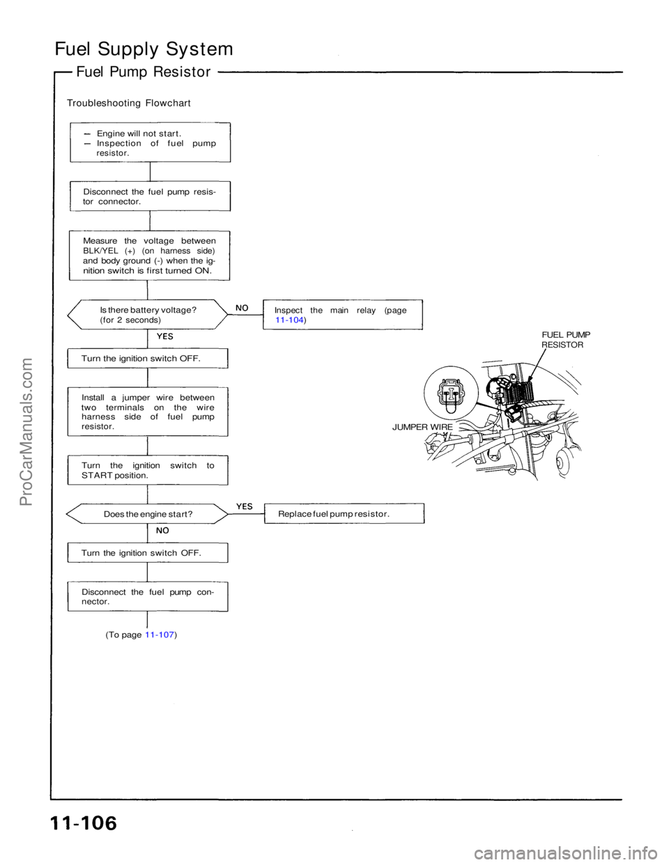
Fuel Supply System
Fuel Pump Resistor
Troubleshooting Flowchart
Engine will not start.
Inspection of fuel pump
resistor.
Disconnect the fuel pump resis-
tor connector.
Measure the voltage between
BLK/YEL (+) (on harness side)
and body ground (-) when the ig-
nition switch is first turned ON.
Is there battery voltage?
(for 2 seconds)
Inspect the main relay (page
11-104)
Turn the ignition switch OFF.
FUEL PUMP
RESISTOR
JUMPER WIRE
Replace fuel pump resistor.
Install a jumper wire between
two terminals on the wire harness side of fuel pump
resistor.
Turn the ignition switch to
START position.
Does the engine start?
Turn the ignition switch OFF.
Disconnect the fuel pump con-
nector.
(To page 11-107)ProCarManuals.com
Page 1514 of 1640
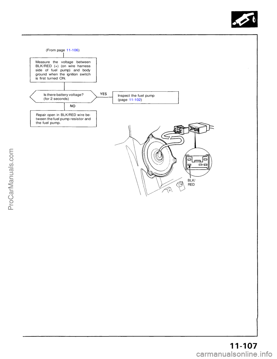
(From page 11-106)
Measure the voltage between
BLK/RED (+) (on wire harness
side of fuel pump) and body
ground when the ignition switch
is first turned ON.
Is there battery voltage?
(for 2 seconds)
Repair open in BLK/RED wire be-
tween the fuel pump resistor and
the fuel pump. Inspect the fuel pump
(page 11-102)
BLK/
REDProCarManuals.com
Page 1515 of 1640
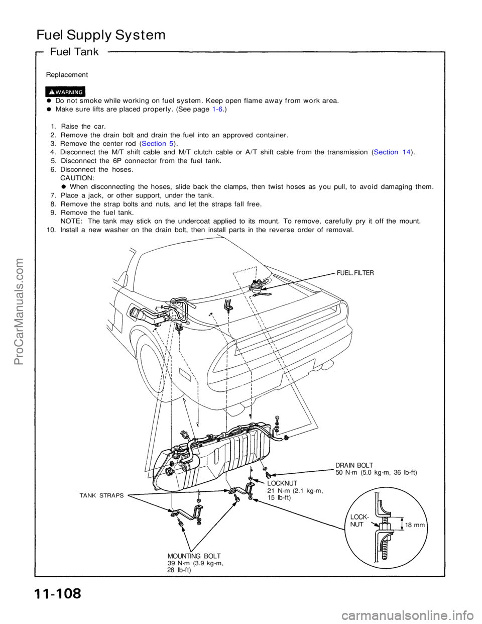
Fuel Supply System
Fuel Tank
Replacement
Do not smoke while working on fuel system. Keep open flame away from work area.Make sure lifts are placed properly. (See page 1-6.)
1. Raise the car.
2. Remove the drain bolt and drain the fuel into an approved container.
3. Remove the center rod (Section 5).
4. Disconnect the M/T shift cable and M/T clutch cable or A/T shift cable from the transmission (Section 14).
5. Disconnect the 6P connector from the fuel tank.
6. Disconnect the hoses. CAUTION: When disconnecting the hoses, slide back the clamps, then twist hoses as you pull, to avoid damaging them.
7. Place a jack, or other support, under the tank.
8. Remove the strap bolts and nuts, and let the straps fall free.
9. Remove the fuel tank. NOTE: The tank may stick on the undercoat applied to its mount. To remove, carefully pry it off the mount.
10. Install a new washer on the drain bolt, then install parts in the reverse order of removal.
FUEL. FILTER
DRAIN BOLT
50 N·m (5.0 kg-m, 36 Ib-ft)
LOCKNUT
21 N·m
(2.1 kg-m,
15 Ib-ft)
TANK STRAPS
LOCK-
NUT
18 mm
MOUNTING BOLT
39 N·m
(3.9 kg-m,
28 Ib-ft)ProCarManuals.com
Page 1516 of 1640
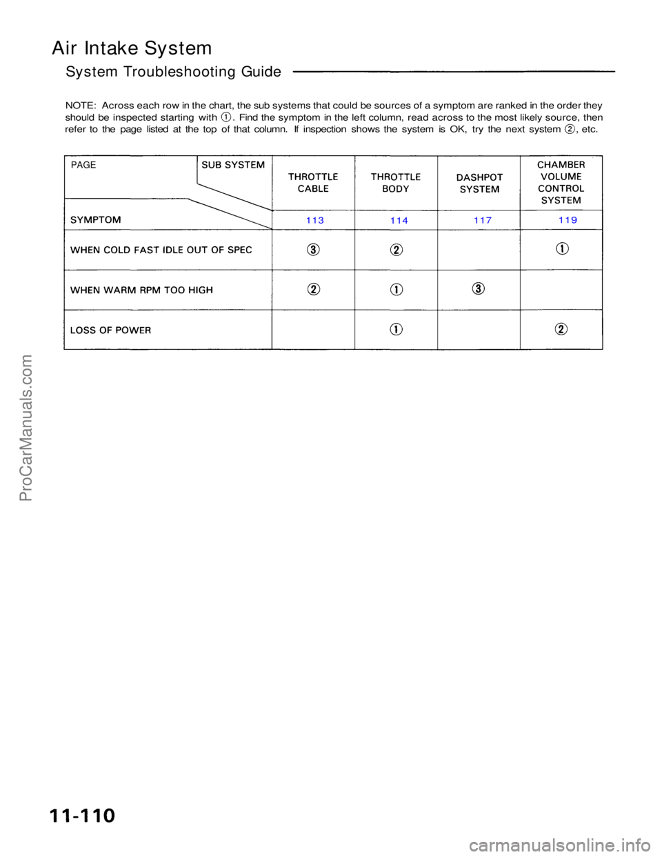
Air Intake System
System Troubleshooting Guide
NOTE: Across each row in the chart, the sub systems that could be sources of a symptom are ranked in the order they should be inspected starting with . Find the symptom in the left column, read across to the most likely source, then
refer to the page listed at the top of that column. If inspection shows the system is OK, try the next system , etc.
PAGE
113
114
117
119
ProCarManuals.com
Page 1517 of 1640
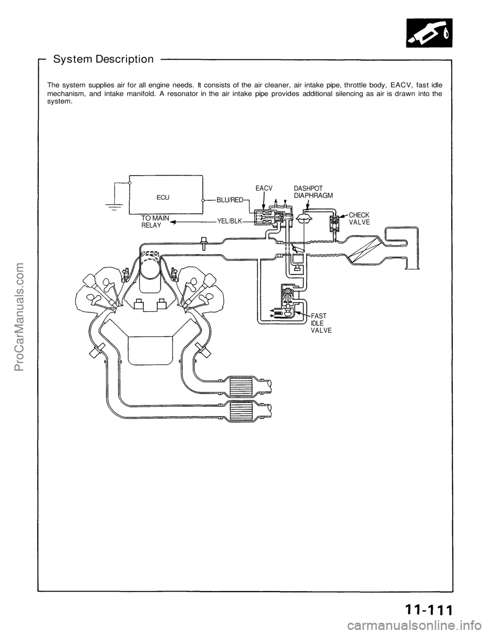
System Description
The system supplies air for all engine needs. It consists of the air cleaner, air intake pipe, throttle body, EACV, fast idle
mechanism, and intake manifold. A resonator in the air intake pipe provides additional silencing as air is drawn into the
system.
ECU
EACV
TO MAIN
RELAY
BLU/RED
CHECK
VALVE
DASHPOT
DIAPHRAGM
YEL/BLK
FAST
IDLE
VALVEProCarManuals.com
Page 1518 of 1640
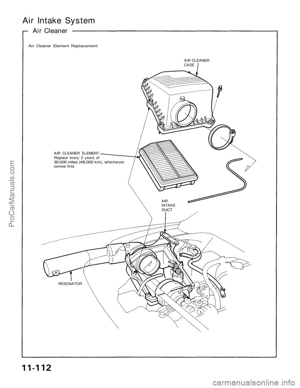
Air Intake System
Air Cleaner
Air Cleaner Element Replacement
AIR CLEANER
CASE
AIR CLEANER ELEMENT
Replace every 2 years of
30,000 miles (48,000 km), whichever
comes first.
AIR
INTAKE
DUCT
RESONATORProCarManuals.com
Page 1519 of 1640
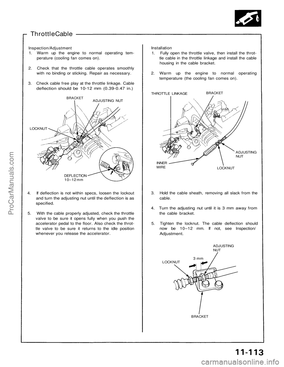
Throttle Cable
Inspection/Adjustment
1. Warm up the engine to normal operating tem-
perature (cooling fan comes on).
2. Check that the throttle cable operates smoothly with no binding or sticking. Repair as necessary.
3. Check cable free play at the throttle linkage. Cable
deflection should be 10-12 mm (0.39-0.47 in.)
Installation
1. Fully open the throttle valve, then install the throt- tle cable in the throttle linkage and install the cablehousing in the cable bracket.
2. Warm up the engine to normal operating temperature (the cooling fan comes on).
THROTTLE LINKAGE
BRACKET
ADJUSTING
NUT
LOCKNUT
INNER
WIRE
ADJUSTING NUT
BRACKET
LOCKNUT
DEFLECTION
10–12
mm
4. If deflection is not within specs, loosen the lockout
and turn the adjusting nut until the deflection is as
specified.
5. With the cable properly adjusted, check the throttle valve to be sure it opens fully when you push the
accelerator pedal to the floor. Also check the throt-
tle valve to be sure it returns to the idle position whenever you release the accelerator. 3. Hold the cable sheath, removing all slack from the
cable.
4. Turn the adjusting nut until it is 3 mm away from
the cable bracket.
5. Tighten the locknut. The cable deflection should now be 10–12 mm. If not, see Inspection/
Adjustment.
ADJUSTING
NUT
LOCKNUT
3 mm
BRACKETProCarManuals.com
Page 1520 of 1640
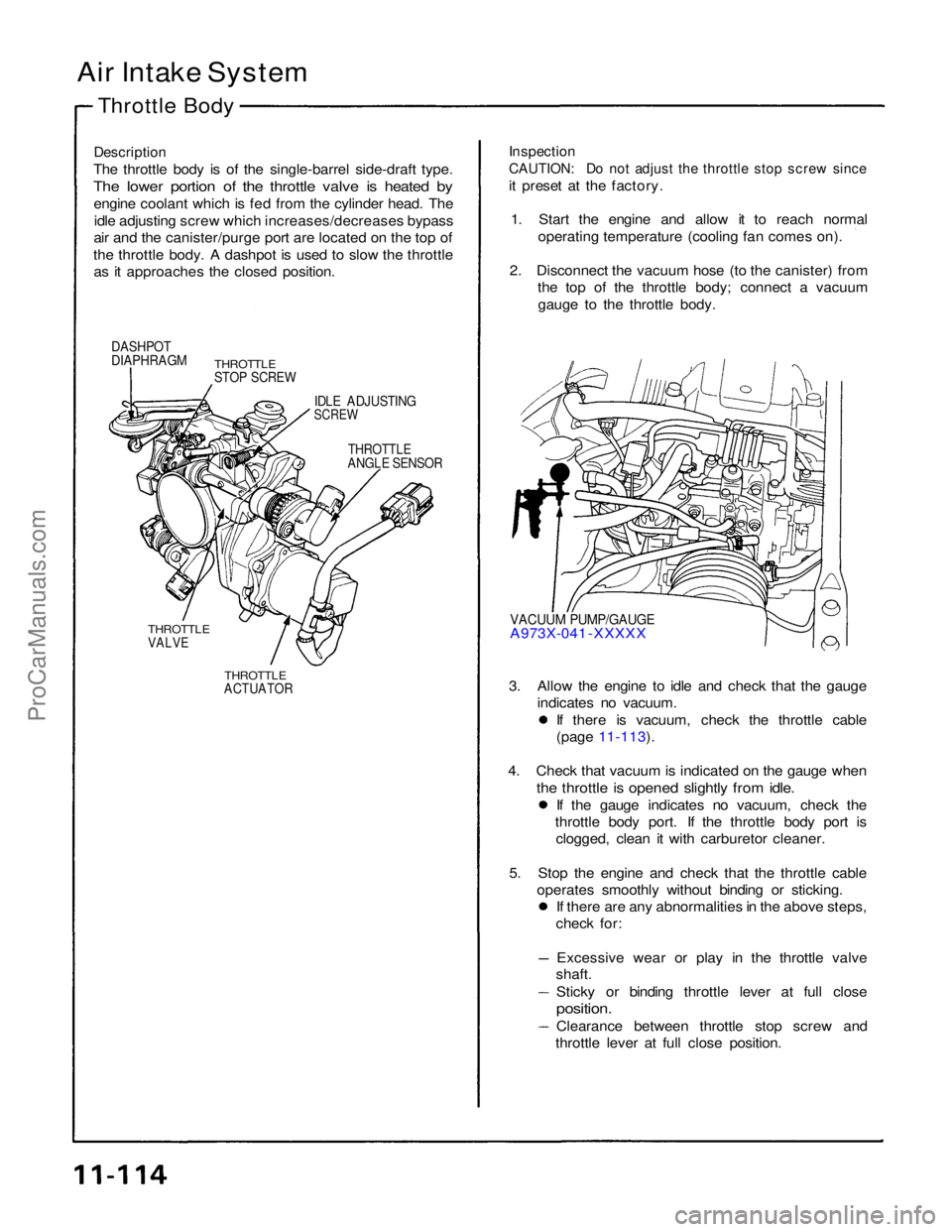
Air Intake System
Throttle Body
Description
The throttle body is of the single-barrel side-draft type.
The lower portion of the throttle valve is heated by
engine coolant which is fed from the cylinder head. Theidle adjusting screw which increases/decreases bypass
air and the canister/purge port are located on the top of
the throttle body. A dashpot is used to slow the throttle as it approaches the closed position.
Inspection
CAUTION: Do not adjust the throttle stop screw since
it preset at the factory.
1. Start the engine and allow it to reach normal operating temperature (cooling fan comes on).
2. Disconnect the vacuum hose (to the canister) from the top of the throttle body; connect a vacuum
gauge to the throttle body.
DASHPOT
DIAPHRAGM
THROTTLE
STOP SCREW
IDLE ADJUSTING
SCREW
THROTTLE
ANGLE SENSOR
VACUUM PUMP/GAUGE
A973X-041 -XXXXX
THROTTLE
VALVE
THROTTLE
ACTUATOR
3. Allow the engine to idle and check that the gauge
indicates no vacuum. If there is vacuum, check the throttle cable
(page 11-113).
4. Check that vacuum is indicated on the gauge when
the throttle is opened slightly from idle.
If the gauge indicates no vacuum, check the
throttle body port. If the throttle body port is clogged, clean it with carburetor cleaner.
5. Stop the engine and check that the throttle cable operates smoothly without binding or sticking. If there are any abnormalities in the above steps,
check for:
Excessive wear or play in the throttle valve
shaft.
Sticky or binding throttle lever at full close
position.
Clearance between throttle stop screw and
throttle lever at full close position.ProCarManuals.com