ACURA NSX 1991 Service Repair Manual
Manufacturer: ACURA, Model Year: 1991,
Model line: NSX,
Model: ACURA NSX 1991
Pages: 1640, PDF Size: 60.48 MB
ACURA NSX 1991 Service Repair Manual
NSX 1991
ACURA
ACURA
https://www.carmanualsonline.info/img/32/56988/w960_56988-0.png
ACURA NSX 1991 Service Repair Manual
Trending: octane, headlights, child lock, oil dipstick, tire size, jack points, low beam
Page 1521 of 1640
Page 1522 of 1640
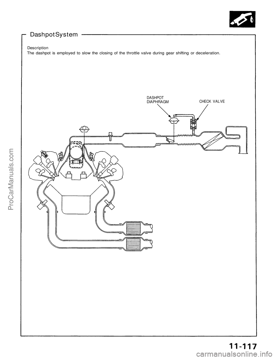
Dashpot System
Description
The dashpot is employed to slow the closing of the throttle valve during gear shifting or deceleration.
DASHPOT
DIAPHRAGM
CHECK VALVEProCarManuals.com
Page 1523 of 1640
Air Intake System
Dashpot System
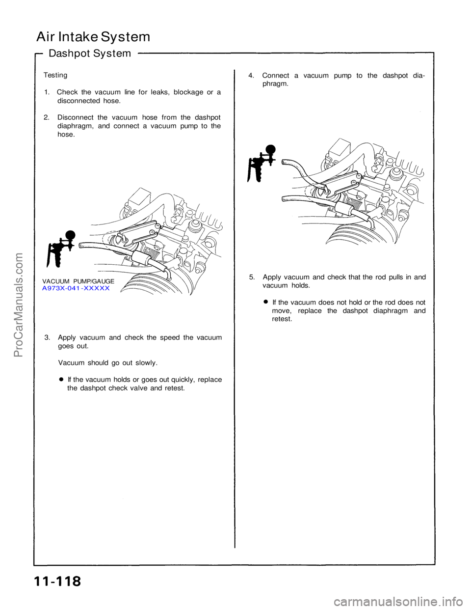
Testing
1. Check the vacuum line for leaks, blockage or a disconnected hose.
2. Disconnect the vacuum hose from the dashpot diaphragm, and connect a vacuum pump to the
hose.
4. Connect a vacuum pump to the dashpot dia-
phragm.
VACUUM PUMP/GAUGE
A973X-041 -XXXXX
5. Apply vacuum and check that the rod pulls in and
vacuum holds. If the vacuum does not hold or the rod does not
move, replace the dashpot diaphragm and
retest.
3. Apply vacuum and check the speed the vacuum goes out.
Vacuum should go out slowly. If the vacuum holds or goes out quickly, replace
the dashpot check valve and retest.ProCarManuals.com
Page 1524 of 1640
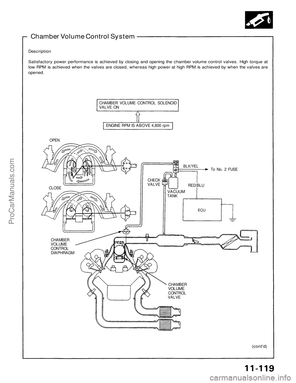
Chamber Volume Control System
Description
Satisfactory power performance is achieved by closing and opening the chamber volume control valves. High torque at
low RPM is achieved when the valves are closed, whereas high power at high RPM is achieved by when the valves are
opened.
CHAMBER VOLUME CONTROL SOLENOID
VALVE ON
ENGINE RPM IS ABOVE 4,800 rpm
OPEN
BLK/YEL
To No. 2 FUSE
CLOSE
CHECK
VALVE
VACUUM
TANK
RED/BLU
ECU
CHAMBER
VOLUME
CONTROL
DIAPHRAGM
CHAMBER
VOLUME
CONTROL
VALVE
(cont'd)ProCarManuals.com
Page 1525 of 1640
Air Intake System
Chamber Volume Control Valve
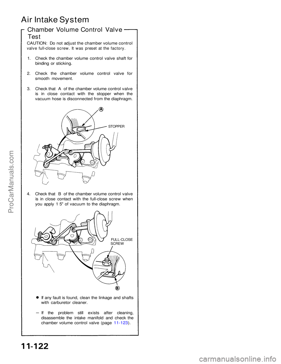
Test
CAUTION: Do not adjust the chamber volume control
valve full-close screw. It was preset at the factory.
1. Check the chamber volume control valve shaft for
binding or sticking.
2. Check the chamber volume control valve for smooth movement.
3. Check that A of the chamber volume control valve is in close contact with the stopper when the
vacuum hose is disconnected from the diaphragm.
STOPPER
4. Check that B of the chamber volume control valve is in close contact with the full-close screw when
you apply 1 5" of vacuum to the diaphragm.
FULL-CLOSE
SCREW
If any fault is found, clean the linkage and shafts
with carburetor cleaner. If the problem still exists after cleaning,
disassemble the intake manifold and check the
chamber volume control valve (page 11-123).ProCarManuals.com
Page 1526 of 1640
Chamber Volume Control System
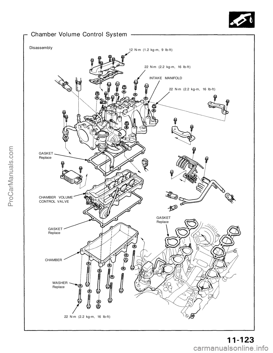
Disassembly
12 N·m (1.2 kg-m, 9 Ib-ft)
22 N·m (2.2 kg-m, 16 Ib-ft)INTAKE MANIFOLD 22 N·m (2.2 kg-m, 16 Ib-ft)
GASKETReplace
CHAMBER VOLUME
CONTROL VALVE
GASKET
Replace
GASKET
Replace
CHAMBER
WASHER
Replace
22 N·m (2.2 kg-m, 16 Ib-ft)ProCarManuals.com
Page 1527 of 1640
Emission Control System
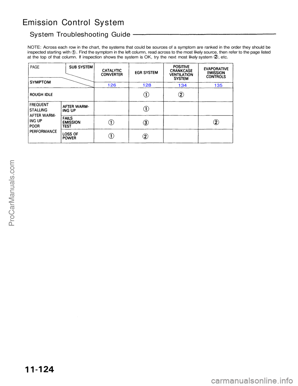
System Troubleshooting Guide
NOTE: Across each row in the chart, the systems that could be sources of a symptom are ranked in the order they should be inspected starting with . Find the symptom in the left column, read across to the most likely source, then refer to the page listed
at the top of that column. If inspection shows the system is OK, try the next most likely system , etc.
PAGE
126
128
134
135
ProCarManuals.com
Page 1528 of 1640
System Description
Tailpipe Emission
The emission control system includes a three-way catalytic converter, exhaust gas recirculation (EGR) system,
crankcase ventilation system and evaporative control
system.
The emission control system is designed to meet federal and
state emission standards.
Inspection
Do not smoke during this procedure. Keep
any open flame away from your work area.
1. Starting the engine and warm it up to normal operating temperature by driving the car on theroad.
2. Connect a tachometer.
3. Check idle speed and adjust the idle speed, if necessary (page 11-84).
4. Warm up and calibrate the CO meter according to the meter manufacturer's instructions.
5. Check idle CO with the headlights, heater blower, rear window defogger, cooling fan, and air conditioner off.
CO meter should indicate 0.1 % maximum.ProCarManuals.com
Page 1529 of 1640
Emission Control System
Catalytic Converter
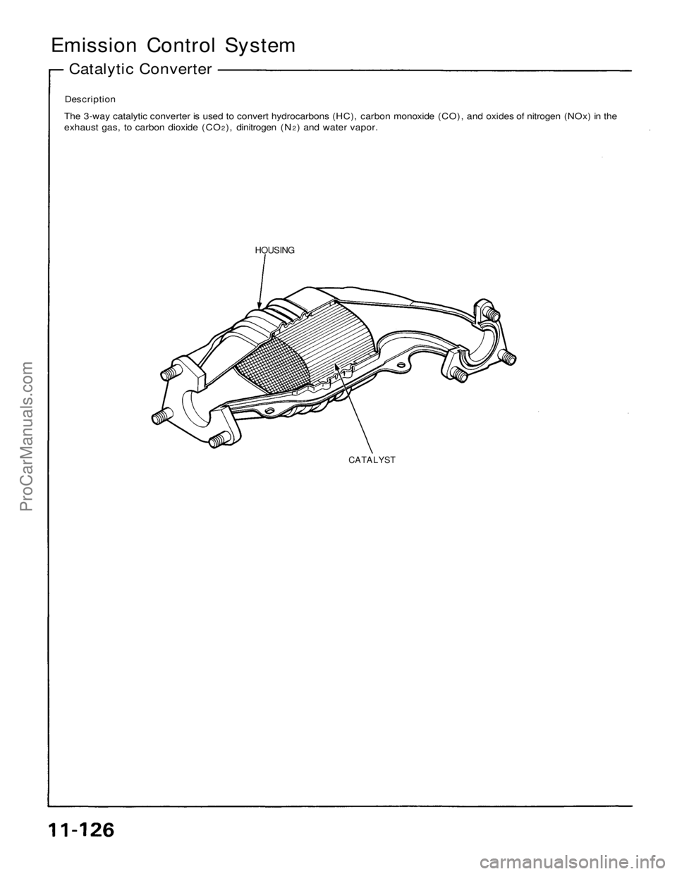
Description
The 3-way catalytic converter is used to convert hydrocarbons (HC), carbon monoxide (CO), and oxides of nitrogen (NOx) in the
exhaust gas, to carbon dioxide (CO2), dinitrogen (N2) and water vapor.
HOUSING
CATALYSTProCarManuals.com
Page 1530 of 1640
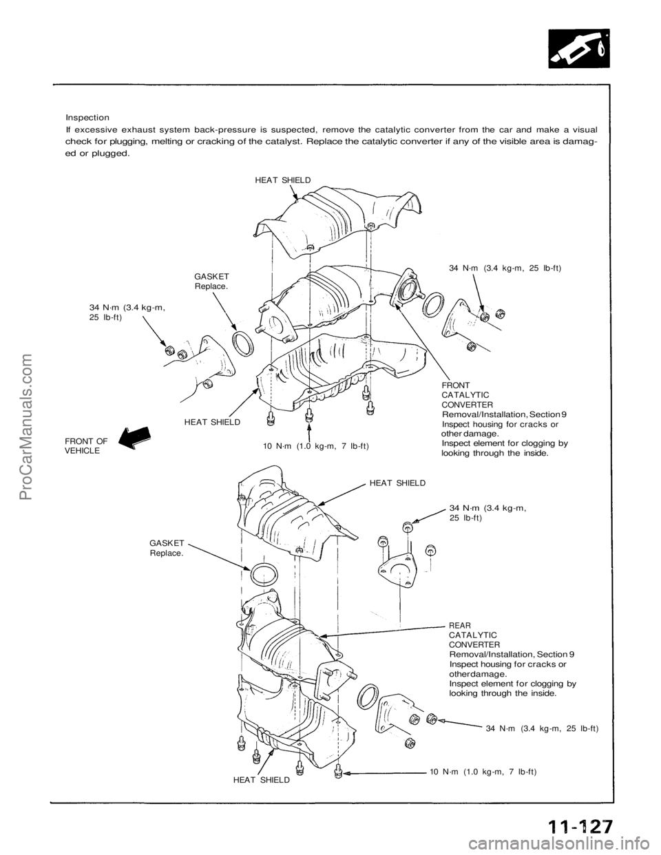
Inspection
If excessive exhaust system back-pressure is suspected, remove the catalytic converter from the car and make a visual
check for plugging, melting or cracking of the catalyst. Replace the catalytic converter if any of the visible area is damag-
ed or plugged.
HEAT SHIELD
GASKET
Replace.
34 N·m
(3.4 kg-m,
25 Ib-ft) 34 N·m (3.4 kg-m, 25 Ib-ft)
HEAT SHIELD 10 N·m (1.0 kg-m, 7 Ib-ft)
HEAT SHIELDFRONT
CATALYTIC
CONVERTER
Removal/Installation, Section 9
Inspect housing for cracks or
other damage.
Inspect element for clogging by
looking through the inside.
FRONT OF
VEHICLE
GASKET
Replace.
34 N·m
(3.4 kg-m,
25 Ib-ft)
REAR
CATALYTIC
CONVERTER
Removal/Installation, Section 9
Inspect housing for cracks or
other damage.
Inspect element for clogging by
looking through the inside.
34 N·m (3.4 kg-m, 25 Ib-ft)
10 N·m (1.0 kg-m, 7 Ib-ft)
HEAT SHIELDProCarManuals.com
Trending: battery replacement, buttons, fog light bulb, mirror, turn signal, horn, wiring
