ACURA NSX 1997 Service Repair Manual
Manufacturer: ACURA, Model Year: 1997, Model line: NSX, Model: ACURA NSX 1997Pages: 1503, PDF Size: 57.08 MB
Page 1061 of 1503
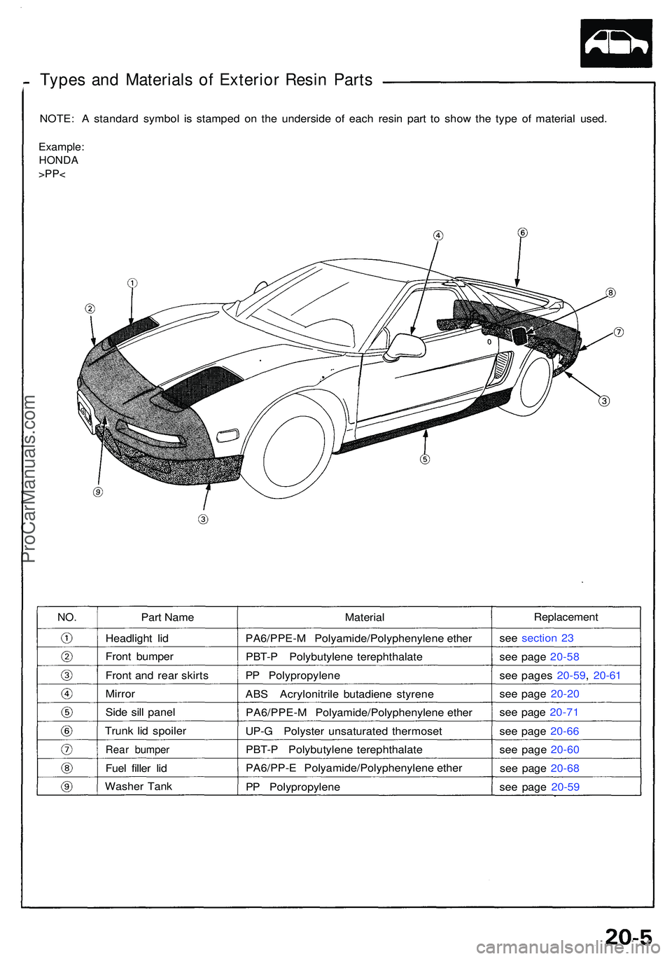
Types an d Material s o f Exterio r Resi n Part s
NOTE : A standar d symbo l i s stampe d o n th e undersid e o f eac h resi n par t t o sho w th e typ e of materia l used .
Example :
HONDA
>PP<
Part Nam e
Headligh t li d
Fron t bumpe r
Fron t an d rea r skirt s
Mirro r
Side sil l pane l
Trun k li d spoile r
Rear bumpe r
Fuel fille r li d
Washe r Tan k Materia
l
PA6/PPE- M Polyamide/Polyphenylen e ethe r
PBT- P Polybutylen e terephthalat e
P P Polypropylen e
AB S Acrylonitril e butadien e styren e
PA6/PPE- M Polyamide/Polyphenylen e ethe r
UP- G Polyste r unsaturate d thermose t
PBT- P Polybutylen e terephthalat e
PA6/PP- E Polyamide/Polyphenylen e ethe r
P P Polypropylen e
Replacement
see sectio n 2 3
se e pag e 20-5 8
se e page s 20-59 , 20-6 1
se e pag e 20-2 0
se e pag e 20-7 1
se e pag e 20-6 6
se e pag e 20-6 0
se e pag e 20-6 8
se e pag e 20-5 9
NO.
ProCarManuals.com
Page 1062 of 1503
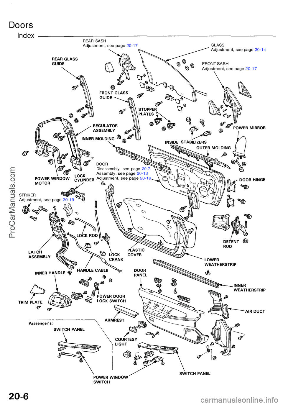
Doors
IndexREA R SAS HAdjustment , se e pag e 20-1 7 GLAS SAdjustment , se e pag e 20-1 4
FRON T SAS H
Adjustment , se e pag e 20-1 7
DOO RDisassembly , se e pag e 20- 7Assembly , se e pag e 20-1 3
Adjustment , se e pag e 20-19 .
STRIKE RAdjustment , se e pag e 20-1 9
ProCarManuals.com
Page 1063 of 1503
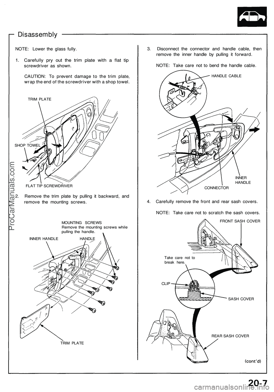
Disassembly
NOTE: Lower the glass fully.
1. Carefully pry out the trim plate with a flat tip
screwdriver as shown.
CAUTION: To prevent damage to the trim plate,
wrap the end of the screwdriver with a shop towel.
TRIM PLATE
SHOP TOWEL
FLAT TIP SCREWDRIVER
2. Remove the trim plate by pulling it backward, and
remove the mounting screws.
MOUNTING SCREWS
Remove the mounting screws while
pulling the handle.
INNER HANDLE HANDLE
TRIM PLATE
3. Disconnect the connector and handle cable, then
remove the inner handle by pulling it forward.
NOTE: Take care not to bend the handle cable.
HANDLE CABLE
INNER
HANDLE
CONNECTOR
4. Carefully remove the front and rear sash covers.
NOTE: Take care not to scratch the sash covers.
FRONT SASH COVER
Take care not to
break here.
CLIP
REAR SASH COVER
SASH COVERProCarManuals.com
Page 1064 of 1503
Doors
Disassembly (cont'd)
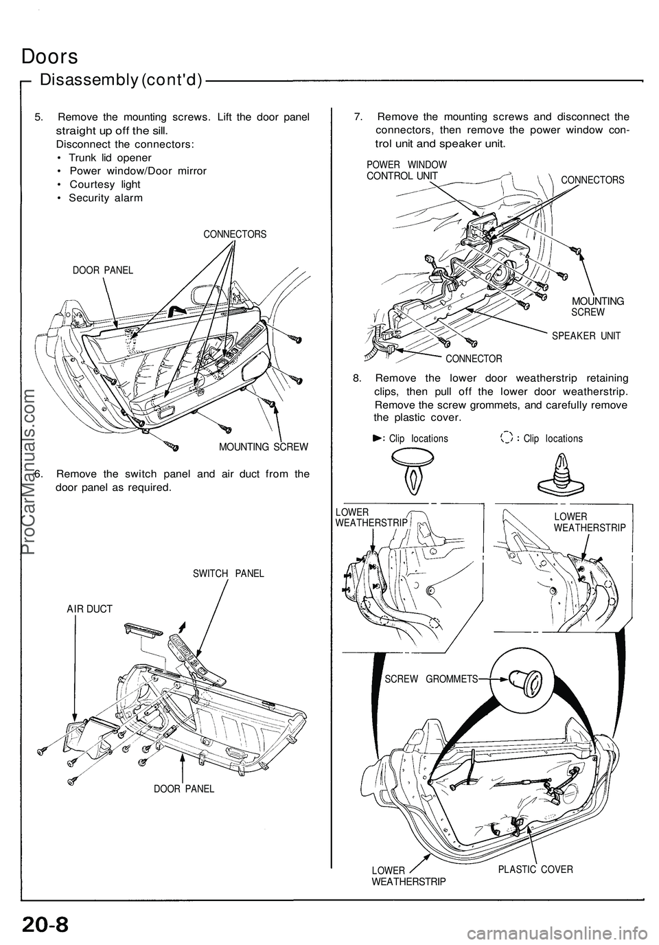
5. Remove the mounting screws. Lift the door panel
straight up off the sill.
Disconnect the connectors:
• Trunk lid opener
• Power window/Door mirror
• Courtesy light
• Security alarm
DOOR PANEL
CONNECTORS
MOUNTING SCREW
6. Remove the switch panel and air duct from the
door panel as required.
SWITCH PANEL
AIR DUCT
DOOR PANEL
7. Remove the mounting screws and disconnect the
connectors, then remove the power window con-
trol unit and speaker unit.
POWER WINDOW
CONTROL UNIT
CONNECTORS
MOUNTING
SCREW
SPEAKER UNIT
CONNECTOR
8. Remove the lower door weatherstrip retaining
clips, then pull off the lower door weatherstrip.
Remove the screw grommets, and carefully remove
the plastic cover.
Clip locations
Clip locations
LOWER
WEATHERSTRIP
PLASTIC COVER
LOWER
WEATHERSTRIP
LOWER
WEATHERSTRIP
SCREW GROMMETSProCarManuals.com
Page 1065 of 1503
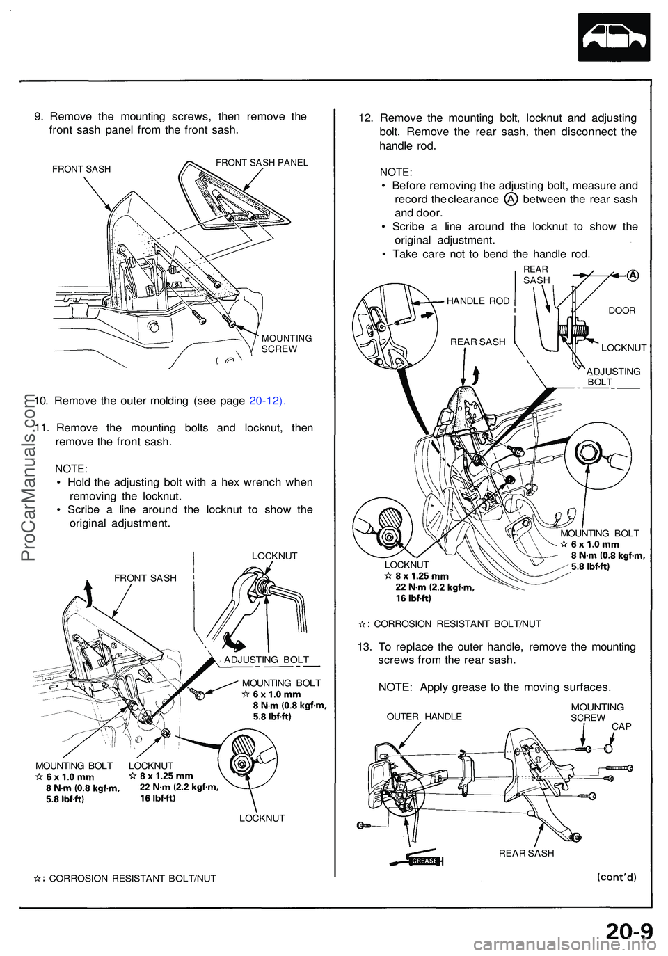
9. Remov e th e mountin g screws , the n remov e th e
fron t sas h pane l fro m th e fron t sash .
FRONT SASH FRONT SASH PANEL
MOUNTIN GSCREW
10. Remov e th e oute r moldin g (se e pag e 20-12) .
11 . Remov e th e mountin g bolt s an d locknut , the n
remov e th e fron t sash .
NOTE :
• Hol d th e adjustin g bol t wit h a he x wrenc h whe n
removin g th e locknut .
• Scrib e a lin e aroun d th e locknu t t o sho w th e
origina l adjustment .
LOCKNUT
MOUNTIN G BOL T
MOUNTIN G BOL T LOCKNU T
LOCKNUT
CORROSIO N RESISTAN T BOLT/NU T
12. Remov e th e mountin g bolt , locknu t an d adjustin g
bolt . Remov e th e rea r sash , the n disconnec t th e
handl e rod .
NOTE :
• Befor e removin g th e adjustin g bolt , measur e an d
recor d th e clearanc e betwee n th e rea r sas h
an d door .
• Scrib e a lin e aroun d th e locknu t t o sho w th e
origina l adjustment .
• Tak e car e no t t o ben d th e handl e rod .
REA RSASH
LOCKNUT
CORROSIO N RESISTAN T BOLT/NU T
13. T o replac e th e oute r handle , remov e th e mountin g
screw s fro m th e rea r sash .
NOTE : Appl y greas e t o th e movin g surfaces .
OUTER HANDL EMOUNTIN GSCREWCAP
REA R SAS H
FRON
T SAS H
ADJUSTING BOL T HANDL
E RO D
DOO R
REAR SAS H
ADJUSTING
BOLT
LOCKNU T
MOUNTIN G BOL T
ProCarManuals.com
Page 1066 of 1503
Doors
Disassembl y (cont'd )
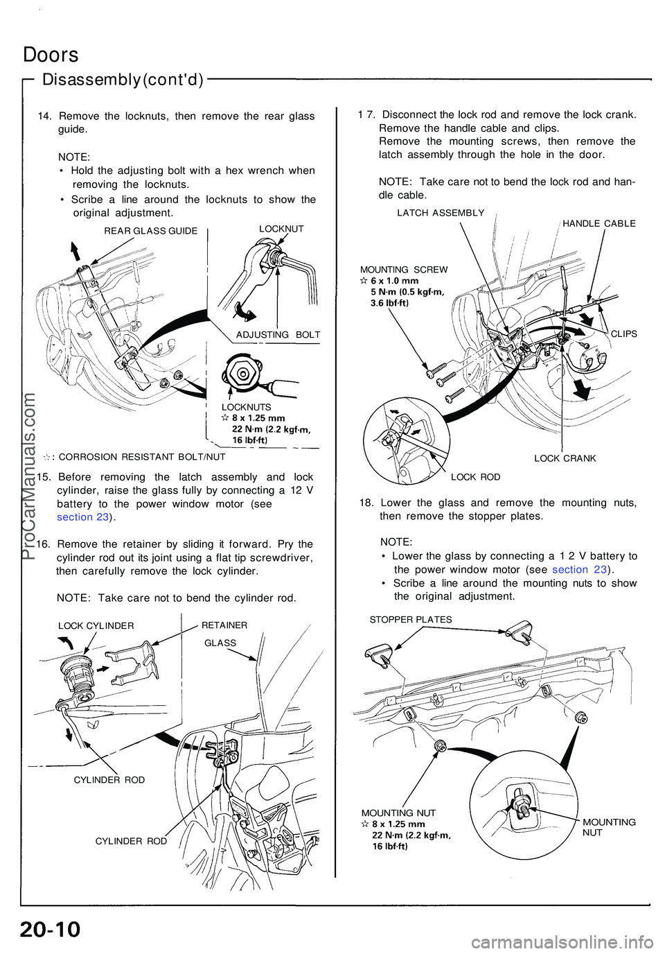
14. Remov e th e locknuts , the n remov e th e rea r glas s
guide .
NOTE :
• Hol d th e adjustin g bol t wit h a he x wrenc h whe n
removin g th e locknuts .
• Scrib e a lin e aroun d th e locknut s t o sho w th e
origina l adjustment .
CORROSION RESISTAN T BOLT/NU T
15. Befor e removin g th e latc h assembl y an d loc k
cylinder , rais e th e glas s full y b y connectin g a 1 2 V
batter y t o th e powe r windo w moto r (se e
section 23 ).
16 . Remov e th e retaine r b y slidin g i t forward . Pr y th e
cylinde r ro d ou t it s join t usin g a fla t ti p screwdriver ,
the n carefull y remov e th e loc k cylinder .
NOTE : Tak e car e no t t o ben d th e cylinde r rod .
LOC K CYLINDE RRETAINER
CYLINDER RO D
1 7 . Disconnec t th e loc k ro d an d remov e th e loc k crank .
Remov e th e handl e cabl e an d clips .
Remov e th e mountin g screws , the n remov e th e
latc h assembl y throug h th e hol e i n th e door .
NOTE : Tak e car e no t t o ben d th e loc k ro d an d han -
dl e cable .
LATCH ASSEMBL Y
HANDLE CABL E
MOUNTIN G SCRE W
CLIPS
LOCK CRAN K
LOC K RO D
18. Lowe r th e glas s an d remov e th e mountin g nuts ,
the n remov e th e stoppe r plates .
NOTE:
• Lowe r th e glas s b y connectin g a 1 2 V batter y t o
th e powe r windo w moto r (se e sectio n 23 ).
• Scrib e a lin e aroun d th e mountin g nut s t o sho w
th e origina l adjustment .
STOPPER PLATE S
MOUNTIN G NU TMOUNTIN GNUT
REA R GLAS S GUID E LOCKNU
T
ADJUSTIN G BOL T
GLAS S
CYLINDE R RO D LOCKNUT
S
ProCarManuals.com
Page 1067 of 1503
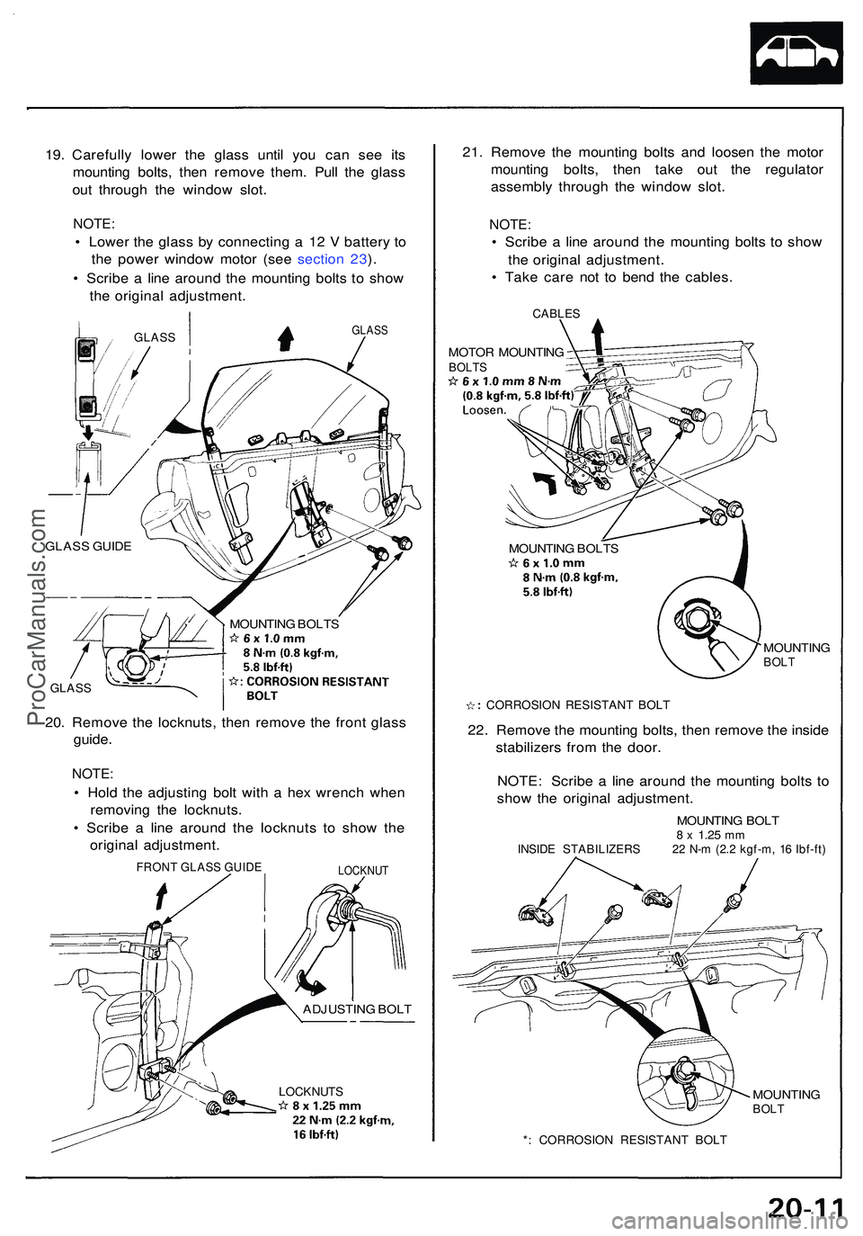
19. Carefull y lowe r th e glas s unti l yo u ca n se e it s
mountin g bolts , the n remov e them . Pul l th e glas s
ou t throug h th e windo w slot .
NOTE :
• Lowe r th e glas s b y connectin g a 1 2 V batter y t o
th e powe r windo w moto r (se e sectio n 23 ).
• Scrib e a lin e aroun d th e mountin g bolt s t o sho w
th e origina l adjustment .
GLASS
GLAS S GUID E
GLAS S
MOUNTIN G BOLT S
20. Remov e th e locknuts , the n remov e th e fron t glas s
guide .
NOTE :
• Hol d th e adjustin g bol t wit h a he x wrenc h whe n
removin g th e locknuts .
• Scrib e a lin e aroun d th e locknut s t o sho w th e
origina l adjustment .
LOCKNUTS
21. Remov e th e mountin g bolt s an d loose n th e moto r
mountin g bolts , the n tak e ou t th e regulato r
assembl y throug h th e windo w slot .
NOTE :
• Scrib e a lin e aroun d th e mountin g bolt s t o sho w
th e origina l adjustment .
• Tak e car e no t t o ben d th e cables .
CABLES
MOTOR MOUNTIN GBOLTS
MOUNTIN G BOLT S
MOUNTING
BOLT
CORROSIO N RESISTAN T BOL T
22. Remov e th e mountin g bolts , the n remov e th e insid e
stabilizer s fro m th e door .
NOTE : Scrib e a lin e aroun d th e mountin g bolt s t o
sho w th e origina l adjustment .
MOUNTING BOL T8 x 1.2 5 mmINSID E STABILIZER S 2 2 N- m (2. 2 kgf-m , 1 6 Ibf-ft )
MOUNTIN GBOLT
*: CORROSIO N RESISTAN T BOL T
GLAS S
FRON T GLAS S GUID ELOCKNU T
ADJUSTIN G BOL T
ProCarManuals.com
Page 1068 of 1503
Doors
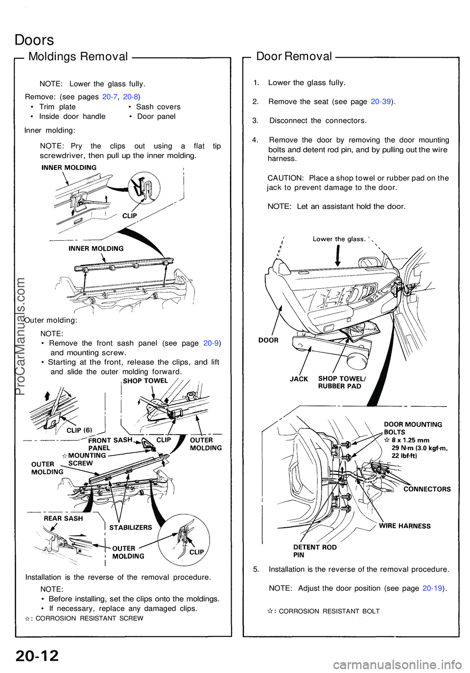
Molding s Remova l
NOTE: Lowe r th e glas s fully .
Remove : (se e page s 20-7 , 20-8 )
• Tri m plat e • Sash cover s
• Insid e doo r handl e • Door pane l
Inne r molding :
NOTE : Pr y th e clip s ou t usin g a fla t ti p
screwdriver , the n pul l u p th e inne r molding .
Outer molding :
NOTE:
• Remov e th e fron t sas h pane l (se e pag e 20-9 )
and mountin g screw .
• Startin g a t th e front , releas e th e clips , an d lif t
and slid e th e oute r moldin g forward .
Installatio n i s th e revers e of the remova l procedure .
NOTE:
• Befor e installing , se t th e clip s ont o th e moldings .
• I f necessary , replac e an y damage d clips .
CORROSIO N RESISTAN T SCRE W
Door Remova l
1. Lowe r th e glas s fully .
2. Remov e th e sea t (se e pag e 20-39 ).
3 . Disconnec t th e connectors .
4 . Remov e th e doo r b y removin g th e doo r mountin g
bolts an d deten t ro d pin , an d b y pullin g ou t th e wir e
harness .
CAUTION : Plac e a sho p towe l o r rubbe r pa d o n th e
jac k t o preven t damag e t o th e door .
NOTE : Le t a n assistan t hol d th e door .
5. Installatio n i s th e revers e o f th e remova l procedure .
NOTE : Adjus t th e doo r positio n (se e pag e 20- 19 ).
CORROSIO N RESISTAN T BOL T
ProCarManuals.com
Page 1069 of 1503
Assembly
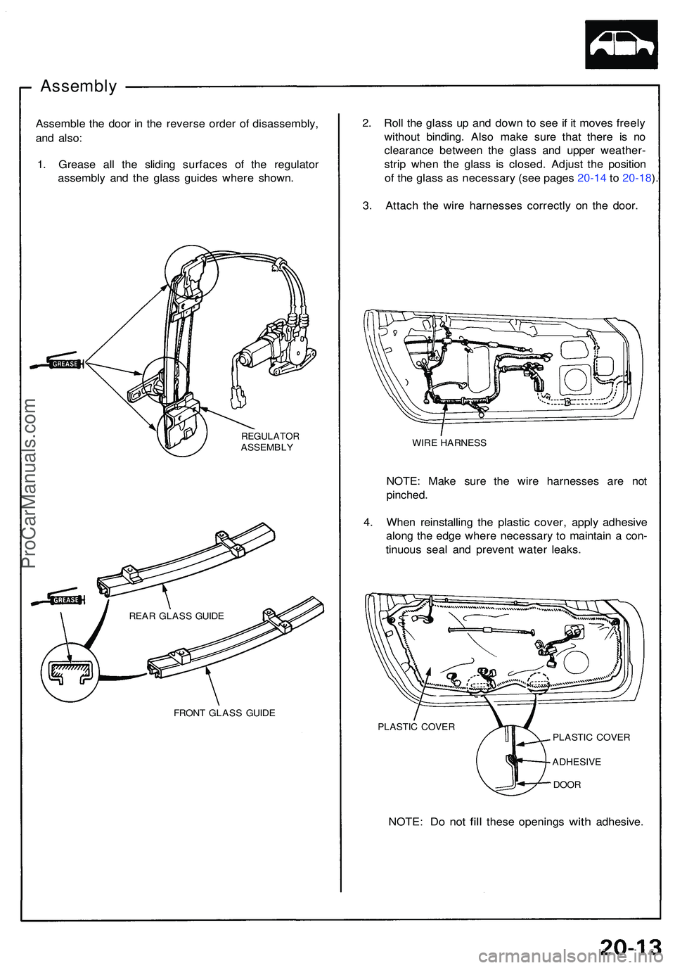
Assemble th e doo r i n th e revers e orde r o f disassembly ,
an d also :
1 . Greas e al l th e slidin g surface s o f th e regulato r
assembl y an d th e glas s guide s wher e shown.
REGULATO RASSEMBLY
FRON T GLAS S GUID E
2. Rol l th e glas s u p an d dow n t o se e if i t move s freel y
withou t binding . Als o mak e sur e tha t ther e i s n o
clearanc e betwee n th e glas s an d uppe r weather -
stri p whe n th e glas s i s closed . Adjus t th e positio n
o f th e glas s a s necessar y (se e page s 20-1 4 t o 20-18 ).
3 . Attac h th e wir e harnesse s correctl y o n th e door .
WIRE HARNES S
NOTE: Mak e sur e th e wir e harnesse s ar e no t
pinched .
4 . Whe n reinstallin g th e plasti c cover , appl y adhesiv e
alon g th e edg e wher e necessar y t o maintai n a con -
tinuou s sea l an d preven t wate r leaks .
REAR GLAS S GUID E
PLASTIC COVE R
PLASTIC COVE R
ADHESIV E
DOOR
NOTE : Do no t fill thes e opening s with adhesive .
ProCarManuals.com
Page 1070 of 1503
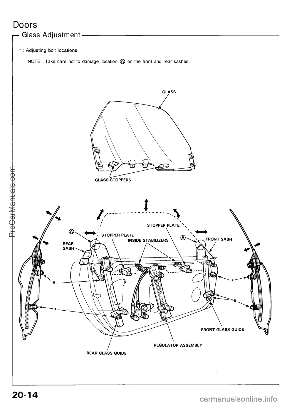
Doors
Glass Adjustment
* : Adjusting bolt locations.
NOTE: Take care not to damage location on the front and rear sashes.ProCarManuals.com