ACURA NSX 1997 Service Repair Manual
Manufacturer: ACURA, Model Year: 1997, Model line: NSX, Model: ACURA NSX 1997Pages: 1503, PDF Size: 57.08 MB
Page 1051 of 1503
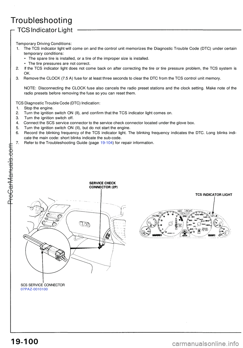
TCS Indicato r Ligh t
Troubleshootin g
Temporary Drivin g Conditions :
1 . Th e TC S indicato r ligh t wil l com e o n an d th e contro l uni t memorize s th e Diagnosti c Troubl e Cod e (DTC ) unde r certai n
temporar y conditions :
• Th e spar e tir e is installed , o r a tir e o f th e imprope r siz e is installed .
• Th e tir e pressure s ar e no t correct .
2 . I f th e TC S indicato r ligh t doe s no t com e bac k o n afte r correctin g th e tir e o r tir e pressur e problem , th e TC S syste m is
OK .
3. Remov e th e CLOC K (7. 5 A ) fus e fo r a t leas t thre e second s t o clea r th e DT C fro m th e TC S contro l uni t memory .
NOTE : Disconnectin g th e CLOC K fus e als o cancel s th e radi o prese t station s an d th e cloc k setting . Mak e not e o f th e
radi o preset s befor e removin g th e fus e s o yo u ca n rese t them .
TC S Diagnosti c Troubl e Cod e (DTC ) Indication :
1 . Sto p th e engine .
2 . Tur n th e ignitio n switc h O N (II) , an d confir m tha t th e TC S indicato r ligh t come s on .
3 . Tur n th e ignitio n switc h off .
4 . Connec t th e SC S servic e connecto r t o th e servic e chec k connecto r locate d unde r th e glov e box .
5 . Tur n th e ignitio n switc h O N (II) , bu t d o no t star t th e engine .
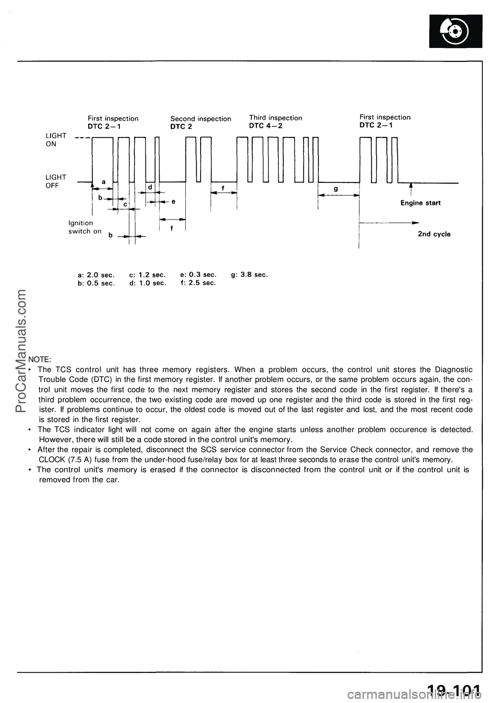
6 . Recor d th e blinkin g frequenc y o f th e TC S indicato r light . Th e blinkin g frequenc y indicate s th e DTC . Lon g blink s indi -
cat e th e mai n code : shor t blink s indicat e th e sub-code .
7 . Refe r t o th e Troubleshootin g Guid e (pag e 19-104 ) fo r repai r information .
SCS SERVIC E CONNECTO R07PAZ-001010 0
ProCarManuals.com
Page 1052 of 1503
NOTE:
• The TCS control unit has three memory registers. When a problem occurs, the control unit stores the Diagnostic
Trouble Code (DTC) in the first memory register. If another problem occurs, or the same problem occurs again, the con-
trol unit moves the first code to the next memory register and stores the second code in the first register. If there's a
third problem occurrence, the two existing code are moved up one register and the third code is stored in the first reg-
ister. If problems continue to occur, the oldest code is moved out of the last register and lost, and the most recent code
is stored in the first register.
• The TCS indicator light will not come on again after the engine starts unless another problem occurence is detected.
However, there will still be a code stored in the control unit's memory.
• After the repair is completed, disconnect the SCS service connector from the Service Check connector, and remove the
CLOCK (7.5 A) fuse from the under-hood fuse/relay box for at least three seconds to erase the control unit's memory.
• The control unit's memory is erased if the connector is disconnected from the control unit or if the control unit is
removed from the car.ProCarManuals.com
Page 1053 of 1503
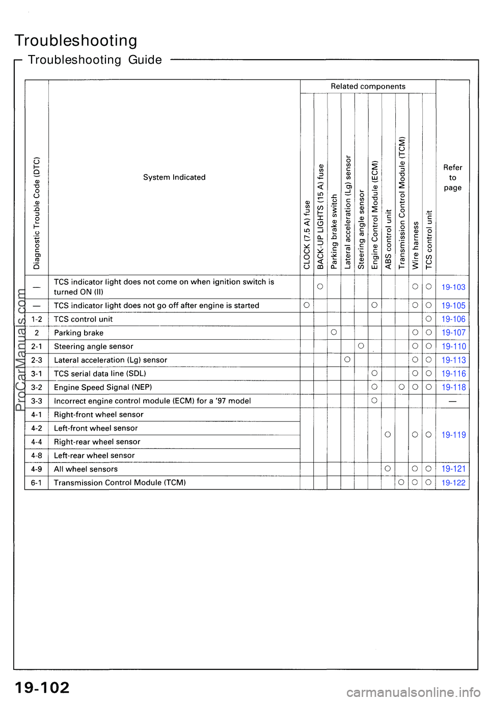
19-103
19-105
19-106
19-107
19-110
19-113
19-116
19-118
19-119
19-121
19-122
Troubleshootin g Guid e
Troubleshootin g
ProCarManuals.com
Page 1054 of 1503
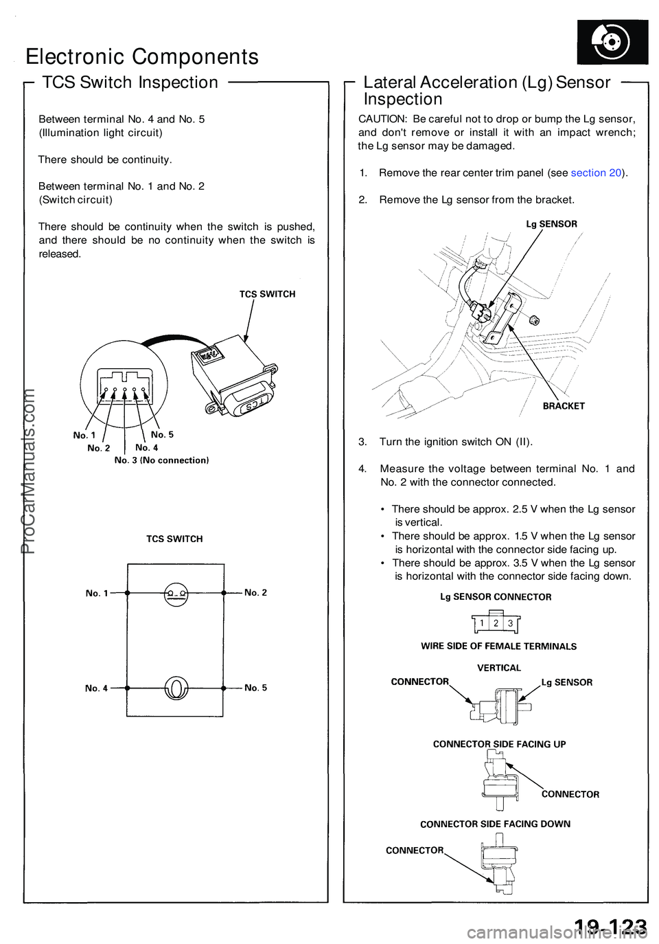
TCS Switc h Inspectio n
Electronic Component s
Between termina l No . 4 an d No . 5
(Illuminatio n ligh t circuit )
Ther e shoul d b e continuity .
Betwee n termina l No . 1 an d No . 2
(Switc h circuit )
Ther e shoul d b e continuit y whe n th e switc h i s pushed ,
an d ther e shoul d b e n o continuit y whe n th e switc h i s
released .
Lateral Acceleratio n (Lg ) Senso r
Inspectio n
CAUTION : B e carefu l no t t o dro p o r bum p th e L g sensor ,
an d don' t remov e o r instal l i t wit h a n impac t wrench ;
th e L g senso r ma y b e damaged .
1 . Remov e th e rea r cente r tri m pane l (se e sectio n 20 ).
2 . Remov e th e L g senso r fro m th e bracket .
3 . Tur n th e ignitio n switc h O N (II) .
4 . Measur e th e voltag e betwee n termina l No . 1 an d
No . 2 wit h th e connecto r connected .
• Ther e shoul d b e approx . 2. 5 V whe n th e L g senso r
i s vertical .
• Ther e shoul d b e approx . 1. 5 V whe n th e L g senso r
i s horizonta l wit h th e connecto r sid e facin g up .
• Ther e shoul d b e approx . 3. 5 V whe n th e L g senso r
i s horizonta l wit h th e connecto r sid e facin g down .
ProCarManuals.com
Page 1055 of 1503
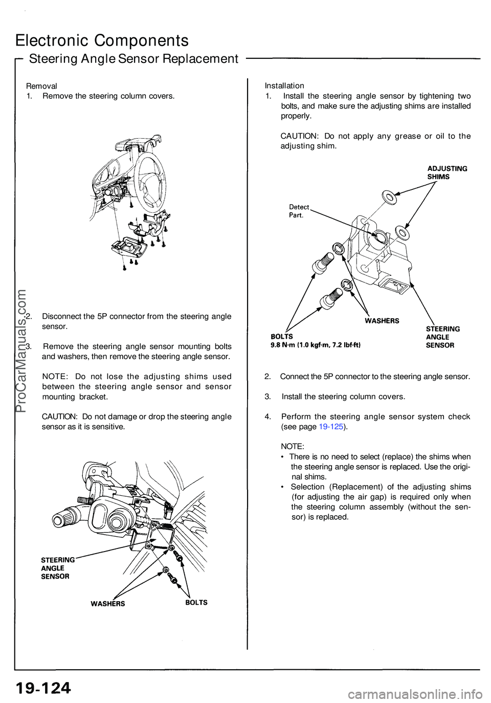
Steering Angl e Senso r Replacemen t
Electronic Component s
Removal
1. Remov e th e steerin g colum n covers . Installatio
n
1 . Instal l th e steerin g angl e senso r b y tightenin g tw o
bolts , an d mak e sur e th e adjustin g shim s ar e installe d
properly .
CAUTION : D o no t appl y an y greas e o r oi l t o th e
adjustin g shim .
2 . Connec t th e 5 P connecto r t o th e steerin g angl e sensor .
3 . Instal l th e steerin g colum n covers .
4 . Perfor m th e steerin g angl e senso r syste m chec k
(se e page 19-125 ).
NOTE :
• Ther e is n o nee d to selec t (replace ) th e shim s whe n
th e steerin g angl e senso r i s replaced . Us e th e origi -
na l shims .
• Selectio n (Replacement ) o f th e adjustin g shim s
(fo r adjustin g th e ai r gap ) i s require d onl y whe n
th e steerin g colum n assembl y (withou t th e sen -
sor ) i s replaced .
2
. Disconnec t th e 5 P connecto r fro m th e steerin g angl e
sensor .
3. Remov e th e steerin g angl e senso r mountin g bolt s
an d washers , the n remov e th e steerin g angl e sensor .
NOTE : D o no t los e th e adjustin g shim s use d
betwee n th e steerin g angl e senso r an d senso r
mountin g bracket .
CAUTION : D o no t damag e o r dro p th e steerin g angl e
senso r a s it i s sensitive .
ProCarManuals.com
Page 1056 of 1503
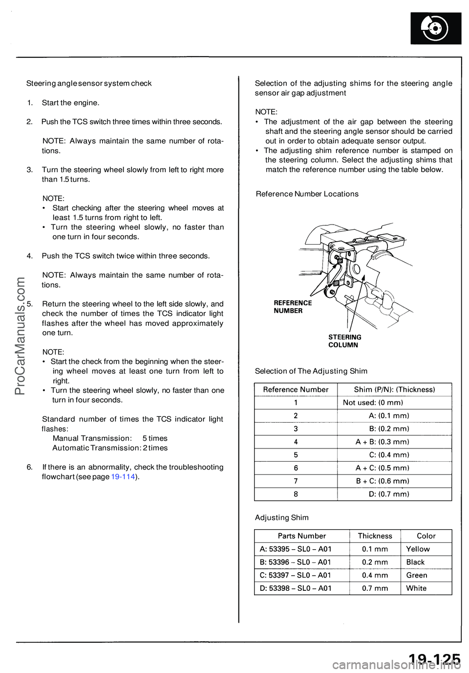
Steering angl e senso r syste m chec k
1 . Star t th e engine .
2 . Pus h th e TC S switc h thre e time s withi n thre e seconds .
NOTE : Alway s maintai n th e sam e numbe r o f rota -
tions .
3 . Tur n th e steerin g whee l slowl y fro m lef t t o righ t mor e
tha n 1. 5 turns .
NOTE :
• Star t checkin g afte r th e steerin g whee l move s a t
leas t 1. 5 turn s fro m righ t t o left .
• Tur n th e steerin g whee l slowly , n o faste r tha n
on e tur n in fou r seconds .
4 . Pus h th e TC S switc h twic e withi n thre e seconds .
NOTE : Alway s maintai n th e sam e numbe r o f rota -
tions .
5 . Retur n th e steerin g whee l t o th e lef t sid e slowly , an d
chec k th e numbe r o f time s th e TC S indicato r ligh t
flashe s afte r th e whee l ha s move d approximatel y
on e turn .
NOTE :
• Star t th e chec k fro m th e beginnin g whe n th e steer -
in g whee l move s a t leas t on e tur n fro m lef t t o
right .
• Tur n th e steerin g whee l slowly , n o faste r tha n on e
tur n in fou r seconds .
Standar d numbe r o f time s th e TC S indicato r ligh t
flashes :
Manual Transmission : 5 time s
Automati c Transmission : 2 time s
6 . I f ther e is a n abnormality , chec k th e troubleshootin g
flowchar t (se e pag e 19-114 ). Selectio
n o f th e adjustin g shim s fo r th e steerin g angl e
senso r ai r ga p adjustmen t
NOTE:
• Th e adjustmen t o f th e ai r ga p betwee n th e steerin g
shaf t an d th e steerin g angl e senso r shoul d b e carrie d
ou t i n orde r t o obtai n adequat e senso r output .
• Th e adjustin g shi m referenc e numbe r i s stampe d o n
th e steerin g column . Selec t th e adjustin g shim s tha t
matc h th e referenc e numbe r usin g th e tabl e below .
Referenc e Numbe r Location s
Selectio n o f Th e Adjustin g Shi m
Adjustin g Shi m
ProCarManuals.com
Page 1057 of 1503
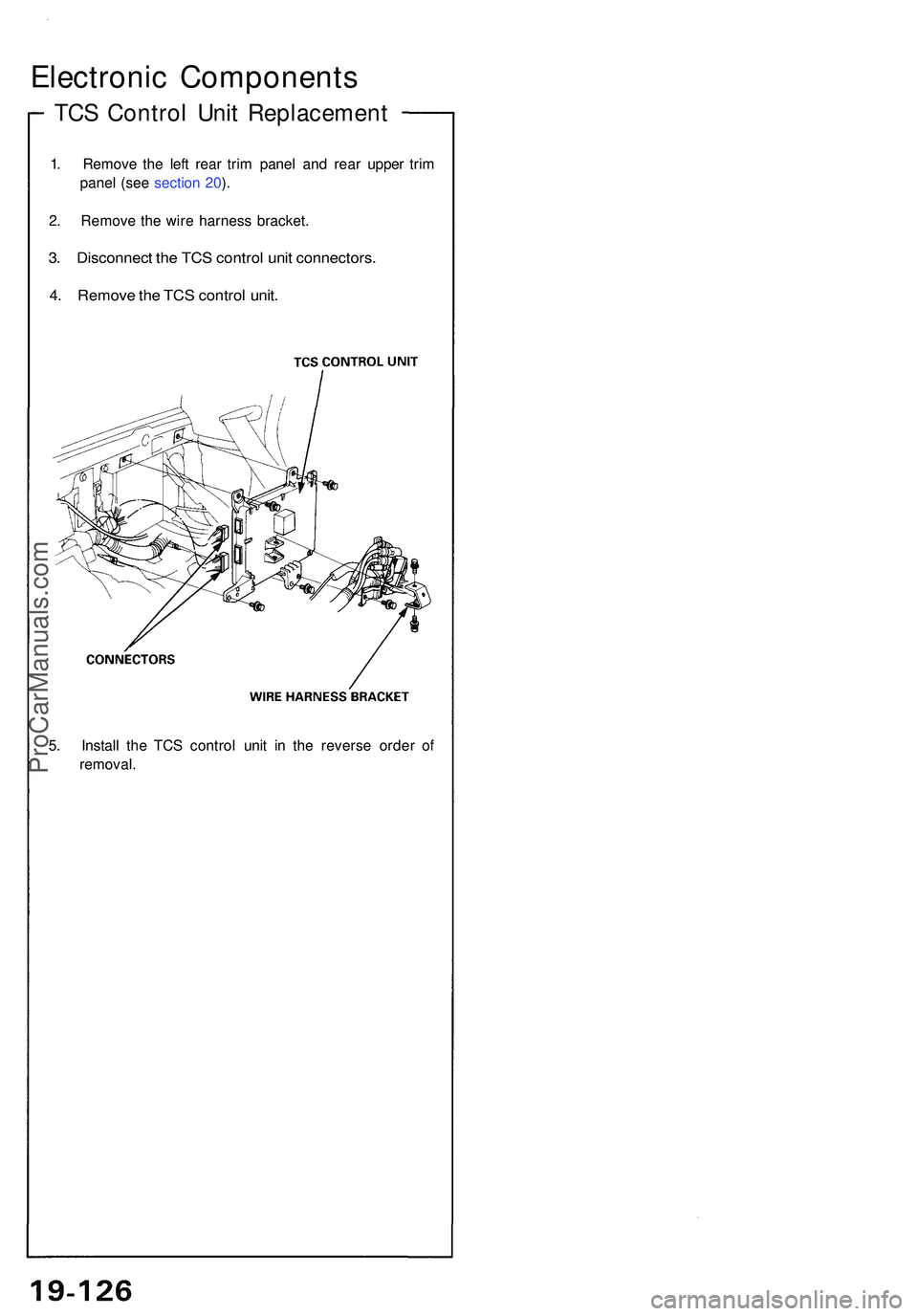
TCS Contro l Uni t Replacemen t
Electronic Component s
1. Remov e th e lef t rea r tri m pane l an d rea r uppe r tri m
pane l (se e sectio n 20 ).
2 . Remov e th e wir e harnes s bracket .
3. Disconnec t th e TC S contro l uni t connectors .
4 . Remov e th e TC S contro l unit .
5. Instal l th e TC S contro l uni t i n th e revers e orde r o f
removal .
ProCarManuals.com
Page 1058 of 1503
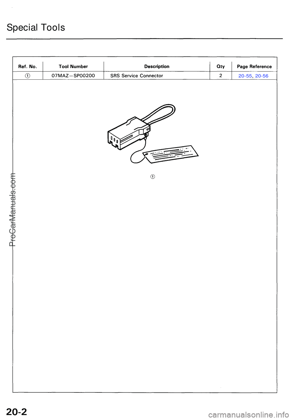
20-55, 20-5 6
Specia l Tool s
ProCarManuals.com
Page 1059 of 1503
Construction
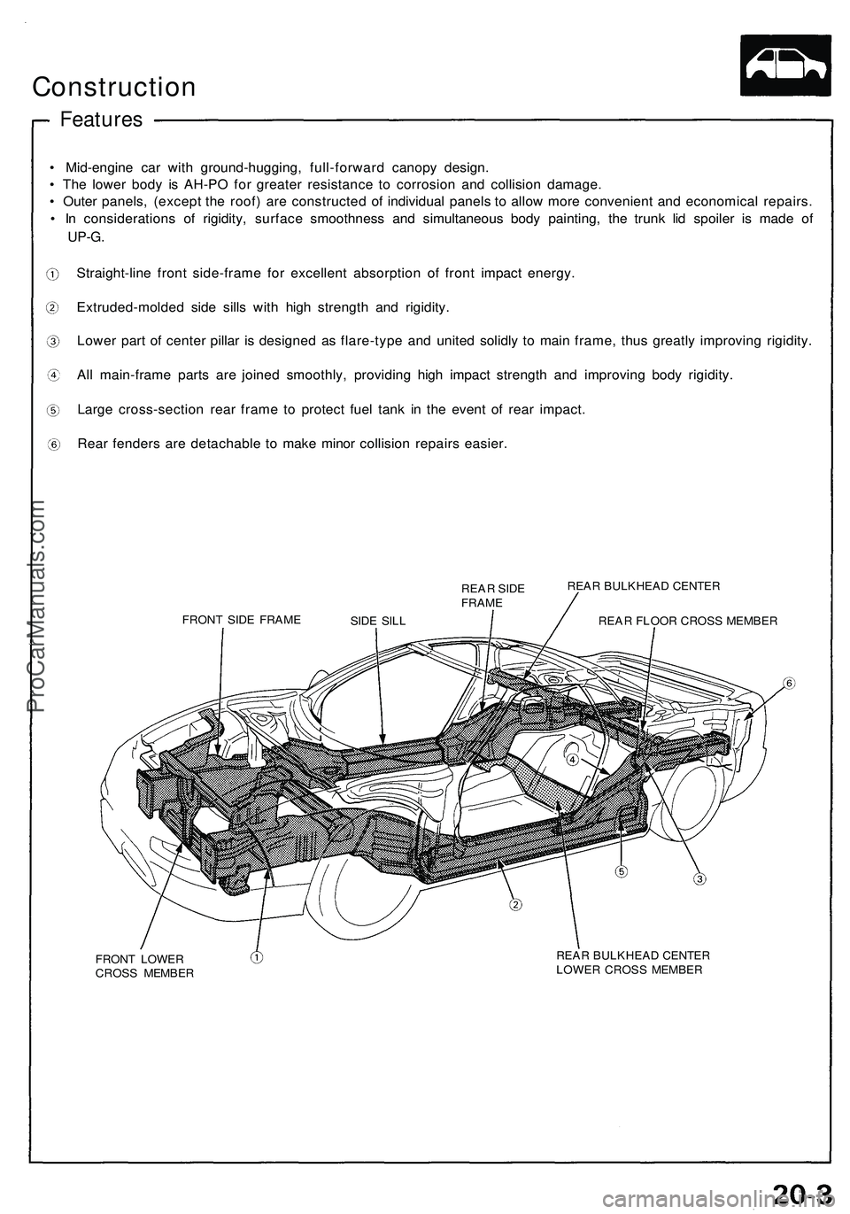
• Mid-engin e ca r wit h ground-hugging , full-forwar d canop y design .
• Th e lowe r bod y i s AH-P O fo r greate r resistanc e t o corrosio n an d collisio n damage .
• Oute r panels , (excep t th e roof ) ar e constructe d o f individua l panel s t o allo w mor e convenien t an d economica l repairs .
• I n consideration s o f rigidity , surfac e smoothnes s an d simultaneou s bod y painting , th e trun k li d spoile r i s mad e of
UP-G .
Straight-lin e fron t side-fram e fo r excellen t absorptio n o f fron t impac t energy .
Extruded-molde d sid e sill s wit h hig h strengt h an d rigidity .
Lowe r par t of cente r pilla r i s designe d a s flare-typ e an d unite d solidl y t o mai n frame , thu s greatl y improvin g rigidity .
Al l main-fram e part s ar e joine d smoothly , providin g hig h impac t strengt h an d improvin g bod y rigidity .
Larg e cross-sectio n rea r fram e t o protec t fue l tan k i n th e even t o f rea r impact .
Rear fender s ar e detachabl e t o mak e mino r collisio n repair s easier .
REAR SID E
FRAM E
FRON T SID E FRAM E REA
R BULKHEA D CENTE R
REA R FLOO R CROS S MEMBE R
FRON T LOWE R
CROS S MEMBE R REA
R BULKHEA D CENTE R
LOWE R CROS S MEMBE R
Features
SIDE SIL L
ProCarManuals.com
Page 1060 of 1503
Construction
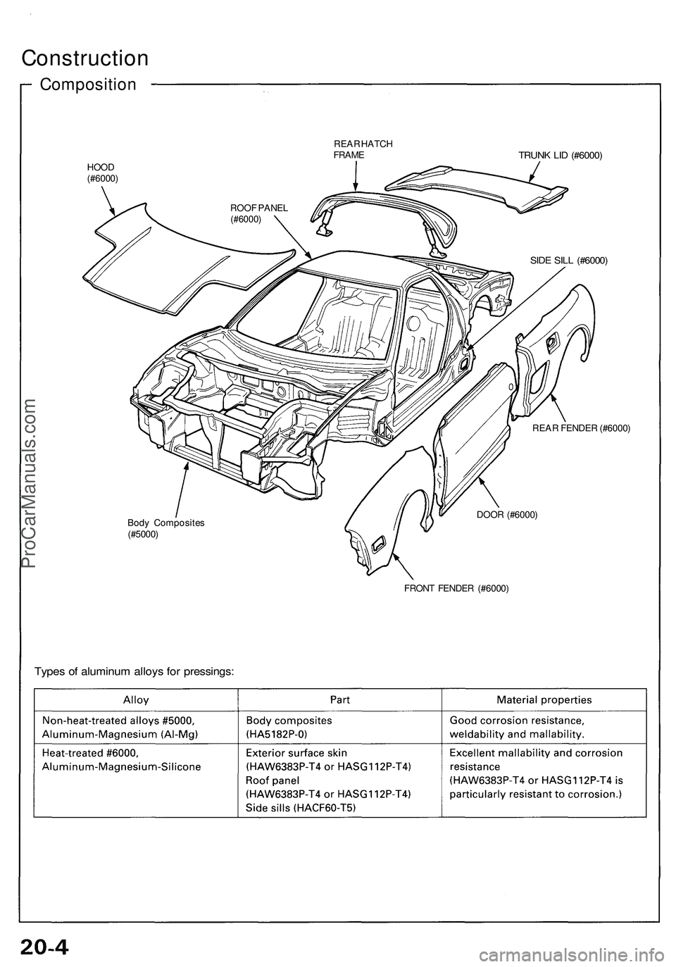
Composition
REAR HATCH
FRAME
TRUNK LID (#6000)
HOOD
(#6000)
SIDE SILL (#6000)
REAR FENDER (#6000)
Body Composites
(#5000)
DOOR (#6000)
FRONT FENDER (#6000)
Types of aluminum alloys for pressings:
ROOF PANEL
(#6000)ProCarManuals.com