ACURA NSX 1997 Service Repair Manual
Manufacturer: ACURA, Model Year: 1997,
Model line: NSX,
Model: ACURA NSX 1997
Pages: 1503, PDF Size: 57.08 MB
ACURA NSX 1997 Service Repair Manual
NSX 1997
ACURA
ACURA
https://www.carmanualsonline.info/img/32/56989/w960_56989-0.png
ACURA NSX 1997 Service Repair Manual
Trending: water pump, OBD port, steering, alternator, fuel type, sport mode, coolant temperature
Page 251 of 1503
Page 252 of 1503
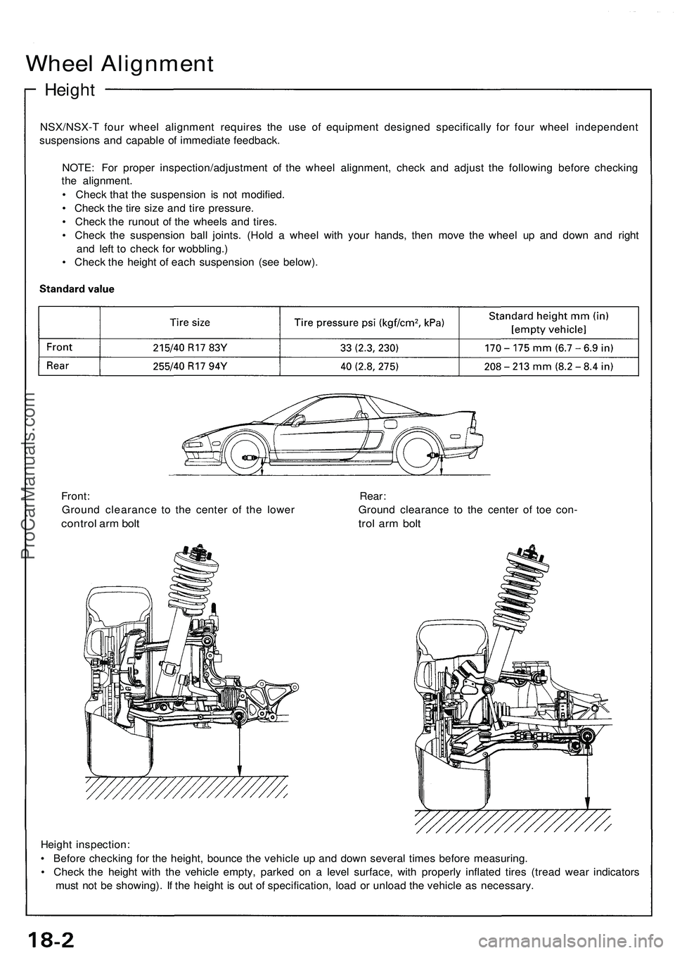
Wheel Alignment
Height
NSX/NSX- T fou r whee l alignmen t require s th e us e o f equipmen t designe d specificall y fo r fou r whee l independen t
suspension s an d capabl e o f immediat e feedback .
NOTE : Fo r prope r inspection/adjustmen t o f th e whee l alignment , chec k an d adjus t th e followin g befor e checkin g
th e alignment .
• Chec k tha t th e suspensio n i s no t modified .
• Chec k th e tir e siz e an d tir e pressure .
• Chec k th e runou t o f th e wheel s an d tires .
• Chec k th e suspensio n bal l joints . (Hol d a whee l wit h you r hands , the n mov e th e whee l u p an d dow n an d righ t
an d lef t t o chec k fo r wobbling. )
• Chec k th e heigh t o f eac h suspensio n (se e below) .
Heigh t inspection :
• Befor e checkin g fo r th e height , bounc e th e vehicl e u p an d dow n severa l time s befor e measuring .
• Chec k th e heigh t wit h th e vehicl e empty , parke d o n a leve l surface , wit h properl y inflate d tire s (trea d wea r indicator s
mus t no t b e showing) . I f th e heigh t i s ou t o f specification , loa d o r unloa d th e vehicl e a s necessary .
Front
: Rear :
Groun d clearanc e t o th e cente r o f th e lowe r Groun d clearanc e t o th e cente r o f toe con -
contro l ar m bol t tro l ar m bol t
ProCarManuals.com
Page 253 of 1503
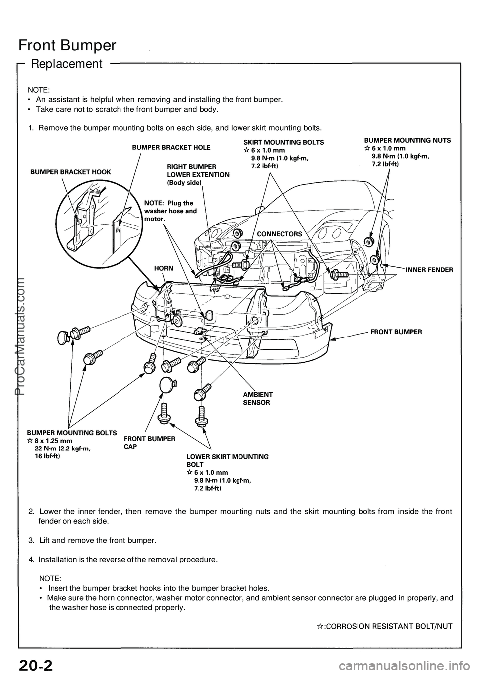
Front Bumpe r
Replacemen t
NOTE:
• A n assistan t i s helpfu l whe n removin g an d installin g th e fron t bumper .
• Tak e car e no t t o scratc h th e fron t bumpe r an d body .
1 . Remov e th e bumpe r mountin g bolt s o n eac h side , an d lowe r skir t mountin g bolts .
2 . Lowe r th e inne r fender , the n remov e th e bumpe r mountin g nut s an d th e skir t mountin g bolt s fro m insid e th e fron t
fende r o n eac h side .
3 . Lif t an d remov e th e fron t bumper .
4 . Installatio n is th e revers e o f th e remova l procedure .
NOTE:
• Inser t th e bumpe r bracke t hook s int o th e bumpe r bracke t holes .
• Mak e sur e th e hor n connector , washe r moto r connector , an d ambien t senso r connecto r ar e plugge d in properly , an d
th e washe r hos e is connecte d properly .
ProCarManuals.com
Page 254 of 1503
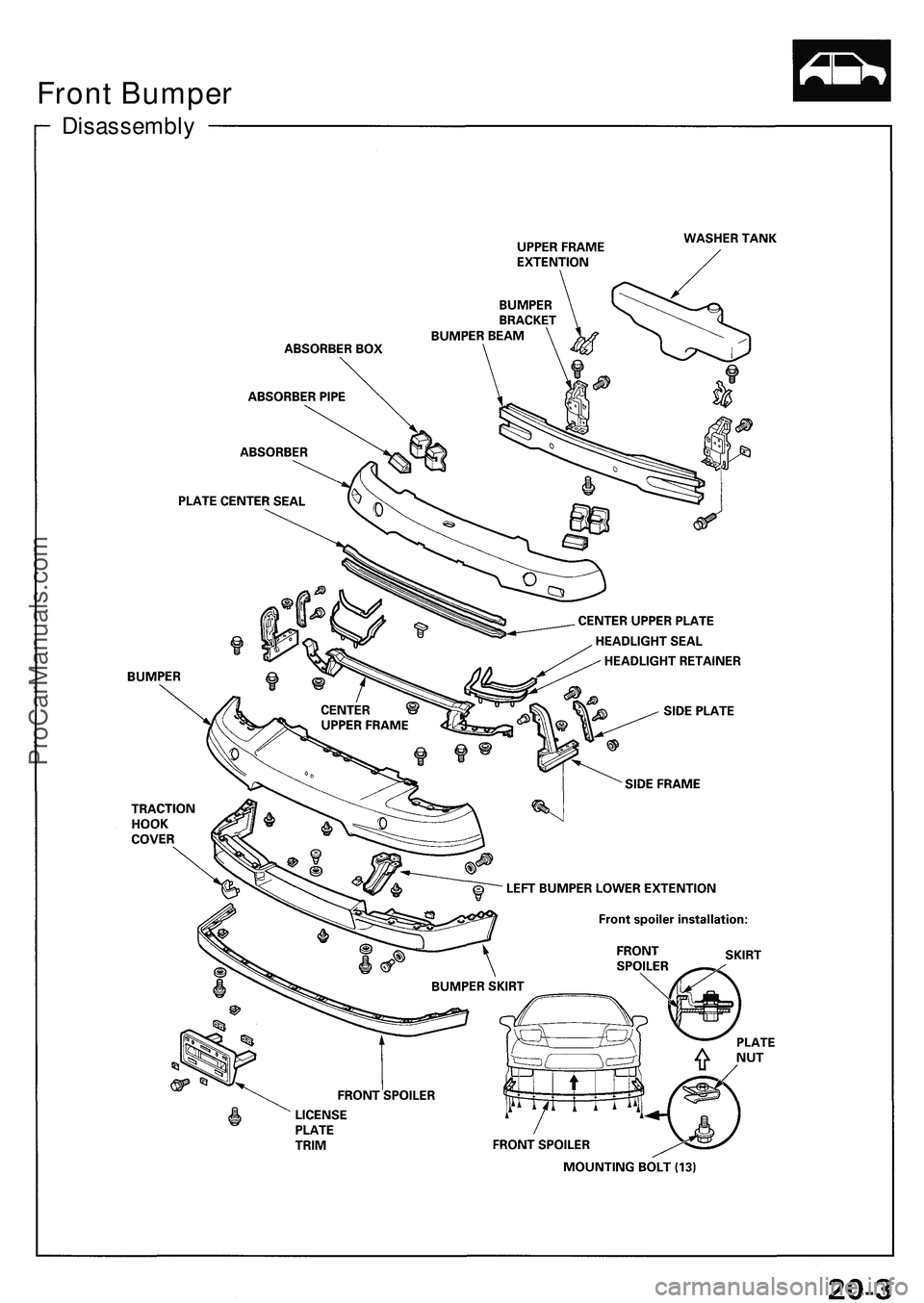
Disassembly
Front Bumper
ProCarManuals.com
Page 255 of 1503
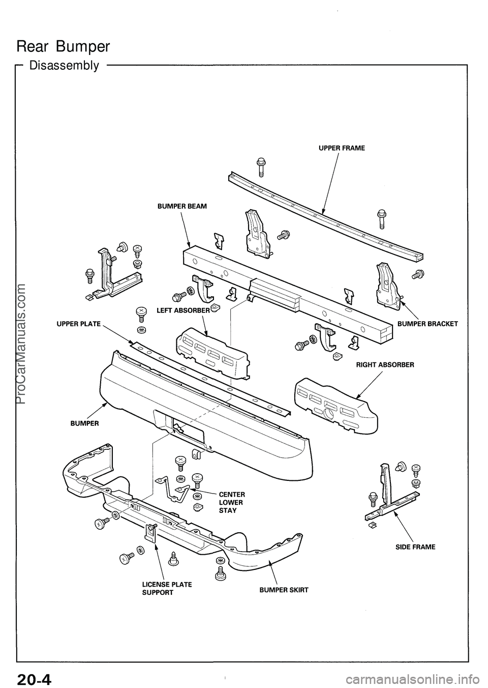
Rear Bumpe r
Disassembl y
ProCarManuals.com
Page 256 of 1503
Bumper Mesh
Replacement
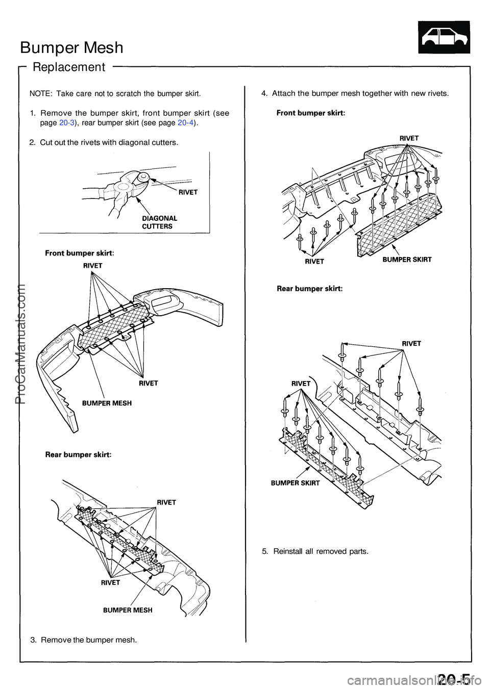
NOTE: Tak e car e no t t o scratc h th e bumpe r skirt .
1. Remov e th e bumpe r skirt , fron t bumpe r skir t (se e
page 20-3 ), rea r bumpe r skir t (se e pag e 20-4 ).
2 . Cu t ou t th e rivet s wit h diagona l cutters .
3 . Remov e th e bumpe r mesh . 4
. Attac h th e bumpe r mes h togethe r wit h ne w rivets .
5 . Reinstal l al l remove d parts .
ProCarManuals.com
Page 257 of 1503
Door lower Trim
Replacement
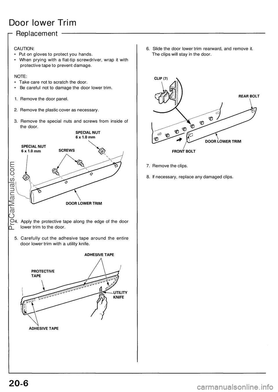
CAUTION:
• Put on gloves to protect you hands.
• When prying with a flat-tip screwdriver, wrap it with
protective tape to prevent damage.
NOTE:
• Take care not to scratch the door.
• Be careful not to damage the door lower trim.
1. Remove the door panel.
2. Remove the plastic cover as necessary.
3. Remove the special nuts and screws from inside of
the door.
6. Slide the door lower trim rearward, and remove it.
The clips will stay in the door.
7. Remove the clips.
8. If necessary, replace any damaged clips.
4. Apply the protective tape along the edge of the door
lower trim to the door.
5. Carefully cut the adhesive tape around the entire
door lower trim with a utility knife.ProCarManuals.com
Page 258 of 1503
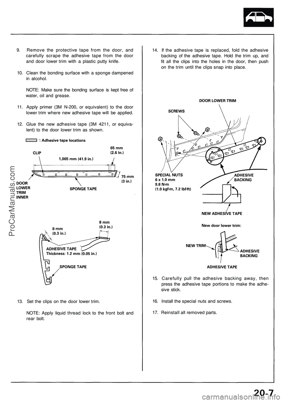
14. If the adhesive tape is replaced, fold the adhesive
backing of the adhesive tape. Hold the trim up, and
fit all the clips into the holes in the door, then push
on the trim until the clips snap into place.
15. Carefully pull the adhesive backing away, then
press the adhesive tape portions to make the adhe-
sive stick.
16. Install the special nuts and screws.
17. Reinstall all removed parts.
13. Set the clips on the door lower trim.
NOTE: Apply liquid thread lock to the front bolt and
rear bolt.
9. Remove the protective tape from the door, and
carefully scrape the adhesive tape from the door
and door lower trim with a plastic putty knife.
10. Clean the bonding surface with a sponge dampened
in alcohol.
NOTE: Make sure the bonding surface is kept free of
water, oil and grease.
11. Apply primer (3M N-200, or equivalent) to the door
lower trim where new adhesive tape will be applied.
12. Glue the new adhesive tape (3M 4211, or equiva-
lent) to the door lower trim as shown.ProCarManuals.com
Page 259 of 1503
Side Sill Panel
Replacement
NOTE:
Take care not to twist the side sill panel.
Take care not to scratch the body and related parts.
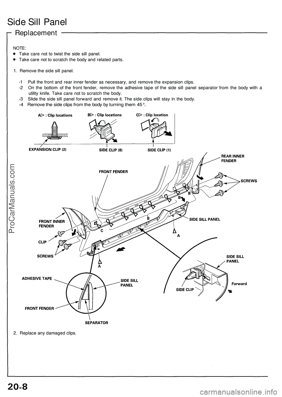
1. Remove the side sill panel.
-1 Pull the front and rear inner fender as necessary, and remove the expansion clips.
-2 On the bottom of the front fender, remove the adhesive tape of the side sill panel separator from the body with a
utility knife. Take care not to scratch the body.
-3 Slide the side sill panel forward and remove it. The side clips will stay in the body.
-4 Remove the side clips from the body by turning them 45
2. Replace any damaged clips.ProCarManuals.com
Page 260 of 1503
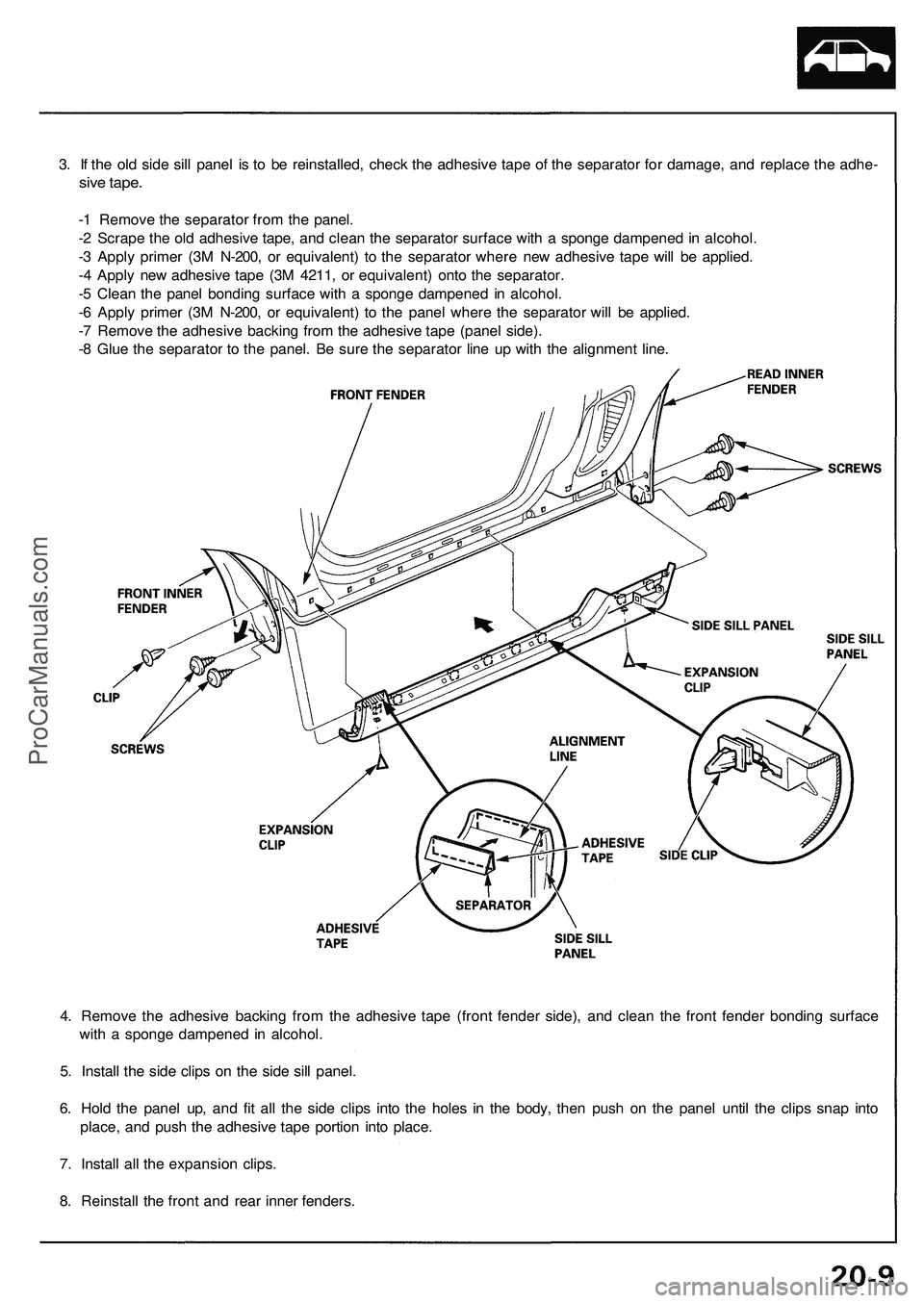
3. If the old side sill panel is to be reinstalled, check the adhesive tape of the separator for damage, and replace the adhe-
sive tape.
-1 Remove the separator from the panel.
-2 Scrape the old adhesive tape, and clean the separator surface with a sponge dampened in alcohol.
-3 Apply primer (3M N-200, or equivalent) to the separator where new adhesive tape will be applied.
-4 Apply new adhesive tape (3M 4211, or equivalent) onto the separator.
-5 Clean the panel bonding surface with a sponge dampened in alcohol.
-6 Apply primer (3M N-200, or equivalent) to the panel where the separator will be applied.
-7 Remove the adhesive backing from the adhesive tape (panel side).
-8 Glue the separator to the panel. Be sure the separator line up with the alignment line.
4. Remove the adhesive backing from the adhesive tape (front fender side), and clean the front fender bonding surface
with a sponge dampened in alcohol.
5. Install the side clips on the side sill panel.
6. Hold the panel up, and fit all the side clips into the holes in the body, then push on the panel until the clips snap into
place, and push the adhesive tape portion into place.
7. Install all the expansion clips.
8. Reinstall the front and rear inner fenders.ProCarManuals.com
Trending: ESP, weight, Brake pedal assembly, child lock, compression ratio, immobilizer, heater
