ACURA NSX 1997 Service Repair Manual
Manufacturer: ACURA, Model Year: 1997, Model line: NSX, Model: ACURA NSX 1997Pages: 1503, PDF Size: 57.08 MB
Page 271 of 1503
Lighting System
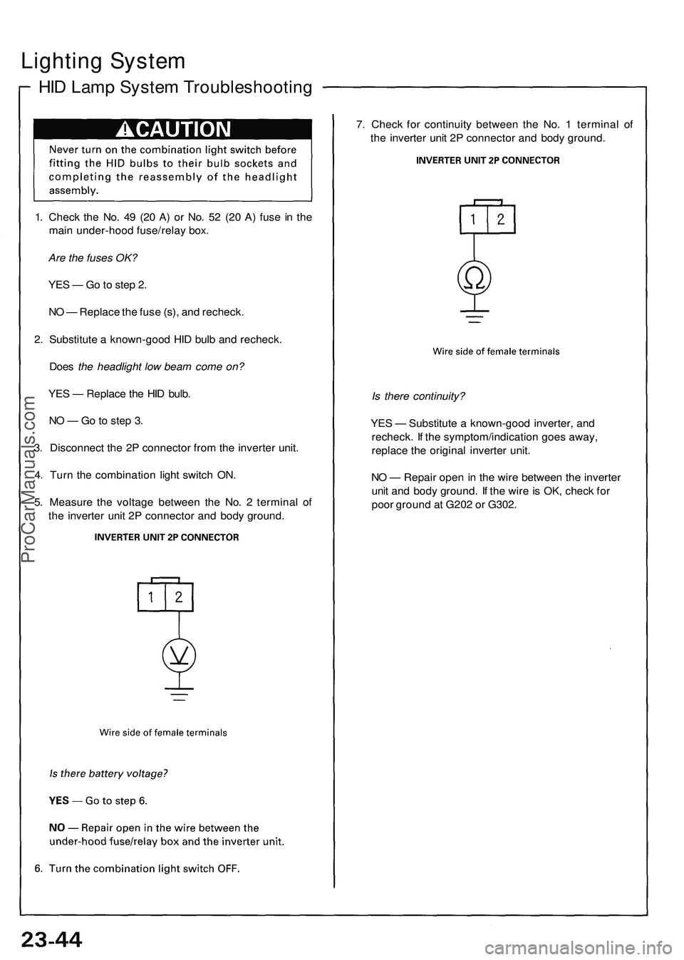
HID Lamp System Troubleshooting
1. Check the No. 49 (20 A) or No. 52 (20 A) fuse in the
main under-hood fuse/relay box.
Are the fuses OK?
YES — Go to step 2.
NO — Replace the fuse (s), and recheck.
2. Substitute a known-good HID bulb and recheck.
Does the headlight low beam come on?
YES — Replace the HID bulb.
NO — Go to step 3.
3. Disconnect the 2P connector from the inverter unit.
4. Turn the combination light switch ON.
5. Measure the voltage between the No. 2 terminal of
the inverter unit 2P connector and body ground.
7. Check for continuity between the No. 1 terminal of
the inverter unit 2P connector and body ground.
Is there continuity?
YES — Substitute a known-good inverter, and
recheck. If the symptom/indication goes away,
replace the original inverter unit.
NO — Repair open in the wire between the inverter
unit and body ground. If the wire is OK, check for
poor ground at G202 or G302.ProCarManuals.com
Page 272 of 1503
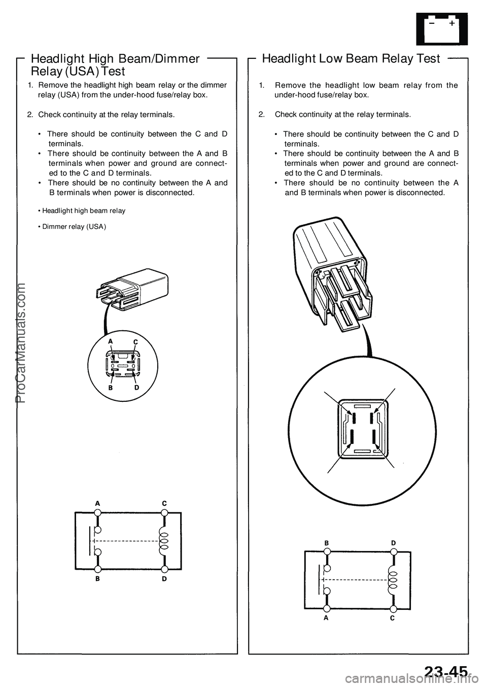
Headlight Low Beam Relay Test
1. Remove the headlight low beam relay from the
under-hood fuse/relay box.
2. Check continuity at the relay terminals.
• There should be continuity between the C and D
terminals.
• There should be continuity between the A and B
terminals when power and ground are connect-
ed to the C and D terminals.
• There should be no continuity between the A
and B terminals when power is disconnected.
Headlight High Beam/Dimmer
Relay (USA) Test
1. Remove the headlight high beam relay or the dimmer
relay (USA) from the under-hood fuse/relay box.
2. Check continuity at the relay terminals.
• There should be continuity between the C and D
terminals.
• There should be continuity between the A and B
terminals when power and ground are connect-
ed to the C and D terminals.
• There should be no continuity between the A and
B terminals when power is disconnected.
• Headlight high beam relay
• Dimmer relay (USA)ProCarManuals.com
Page 273 of 1503
Lighting Syste m
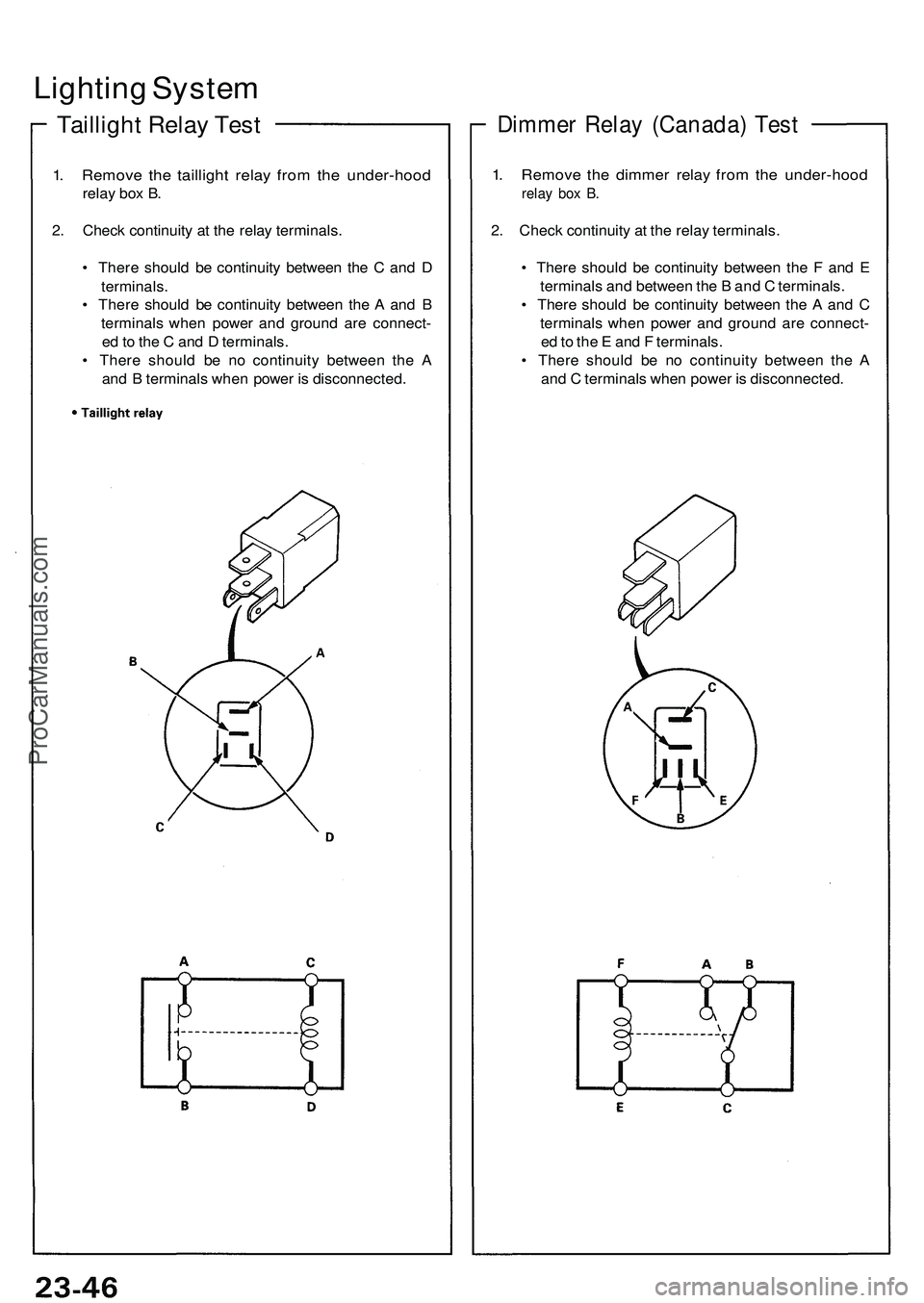
Tailligh t Rela y Tes t
1. Remov e th e tailligh t rela y fro m th e under-hoo d
relay bo x B .
2 . Chec k continuit y a t th e rela y terminals .
• Ther e shoul d b e continuit y betwee n th e C an d D
terminals .
• Ther e shoul d b e continuit y betwee n th e A an d B
terminal s whe n powe r an d groun d ar e connect -
e d to th e C an d D terminals .
• Ther e shoul d b e n o continuit y betwee n th e A
an d B terminal s whe n powe r i s disconnected .
Dimmer Rela y (Canada ) Tes t
1. Remov e th e dimme r rela y fro m th e under-hoo d
relay bo x B .
2. Chec k continuit y a t th e rela y terminals .
• Ther e shoul d b e continuit y betwee n th e F an d E
terminal s an d betwee n th e B an d C terminals .
• Ther e shoul d b e continuit y betwee n th e A an d C
terminal s whe n powe r an d groun d ar e connect -
e d to th e E an d F terminals .
• Ther e shoul d b e n o continuit y betwee n th e A
an d C terminal s whe n powe r i s disconnected .
ProCarManuals.com
Page 274 of 1503
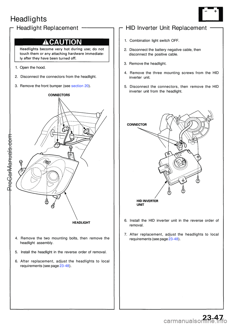
4. Remov e th e tw o mountin g bolts , the n remov e th e
headligh t assembly .
5 . Instal l th e headligh t i n th e revers e orde r o f removal .
6 . Afte r replacement , adjus t th e headlight s t o loca l
requirement s (se e pag e 23-48 ).
Headlight s
Headlight Replacemen t
1. Ope n th e hood .
2. Disconnec t th e connector s fro m th e headlight .
3 . Remov e th e fron t bumpe r (se e sectio n 20 ).
HI D Inverte r Uni t Replacemen t
1. Combinatio n ligh t switc h OFF .
2 . Disconnec t th e batter y negativ e cable , the n
disconnec t th e positiv e cable .
3 . Remov e th e headlight .
4 . Remov e th e thre e mountin g screw s fro m th e HI D
inverte r unit .
5 . Disconnec t th e connectors , the n remov e th e HI D
inverte r uni t fro m th e headlight .
6 . Instal l th e HI D inverte r uni t i n th e revers e orde r o f
removal .
7 . Afte r replacement , adjus t th e headlight s t o loca l
requirement s (se e pag e 23-48 ).
ProCarManuals.com
Page 275 of 1503
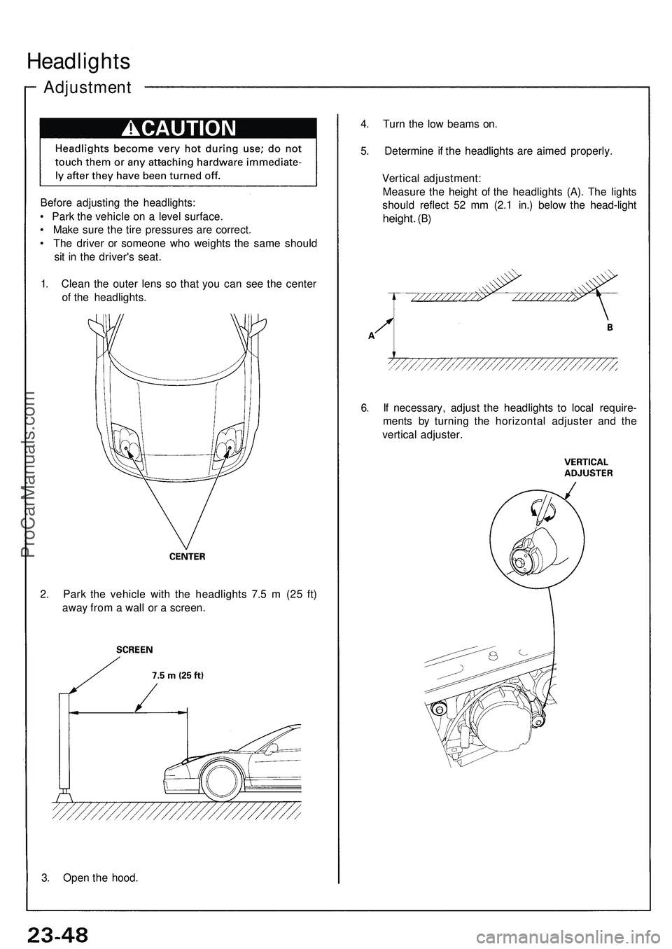
Headlights
Adjustmen t
Before adjustin g th e headlights :
• Par k th e vehicl e o n a leve l surface .
• Mak e sur e th e tir e pressure s ar e correct .
• Th e drive r o r someon e wh o weight s th e sam e shoul d
si t i n th e driver' s seat .
1 . Clea n th e oute r len s s o tha t yo u ca n se e th e cente r
o f th e headlights . 4
. Tur n th e lo w beam s on .
5 . Determin e i f th e headlight s ar e aime d properly .
Vertica l adjustment :
Measur e th e heigh t o f th e headlight s (A) . Th e light s
shoul d reflec t 5 2 m m (2. 1 in. ) belo w th e head-ligh t
height. (B)
6. I f necessary , adjus t th e headlight s t o loca l require -
ment s b y turnin g th e horizonta l adjuste r an d th e
vertica l adjuster .
2 . Par k th e vehicl e wit h th e headlight s 7. 5 m (2 5 ft )
awa y fro m a wal l o r a screen .
3 . Ope n th e hood .
ProCarManuals.com
Page 276 of 1503
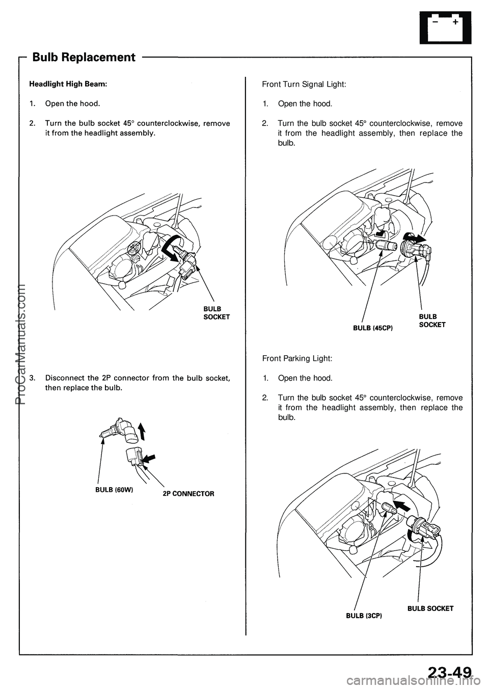
Front Turn Signal Light:
1. Open the hood.
2. Turn the bulb socket 45° counterclockwise, remove
it from the headlight assembly, then replace the
bulb.
Front Parking Light:
1. Open the hood.
2. Turn the bulb socket 45° counterclockwise, remove
it from the headlight assembly, then replace the
bulb.ProCarManuals.com
Page 277 of 1503
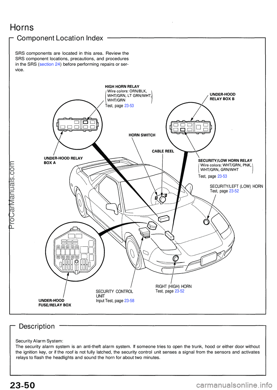
Description
Security Alar m System :
Th e securit y alar m syste m is a n anti-thef t alar m system . I f someon e trie s t o ope n th e trunk , hoo d o r eithe r doo r withou t
th e ignitio n key , o r i f th e roo f i s no t full y latched , th e securit y contro l uni t sense s a signa l fro m th e sensor s an d activate s
relay s t o flas h th e headlight s an d soun d th e hor n fo r abou t tw o minutes .
SECURIT Y CONTRO LUNITInpu t Test , pag e 23-5 8
RIGH T (HIGH ) HOR N
Test , pag e 23-5 2
Horn s
Componen t Locatio n Inde x
SRS component s ar e locate d i n thi s area . Revie w th e
SR S componen t locations , precautions , an d procedure s
i n th e SR S (sectio n 24 ) befor e performin g repair s o r ser -
vice .
Test , pag e 23-5 3
Test, pag e 23-5 3
SECURITY/LEF T (LOW ) HOR N
Test , pag e 23-5 2
ProCarManuals.com
Page 278 of 1503
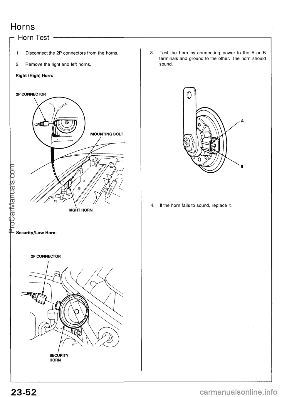
Horns
Horn Tes t
1. Disconnec t th e 2 P connector s fro m th e horns .
2 . Remov e th e righ t an d lef t horns . 3
. Tes t th e hor n b y connectin g powe r t o th e A or B
terminal s an d groun d t o th e other . Th e hor n shoul d
sound .
4 . I f th e hor n fail s t o sound , replac e it .
ProCarManuals.com
Page 279 of 1503
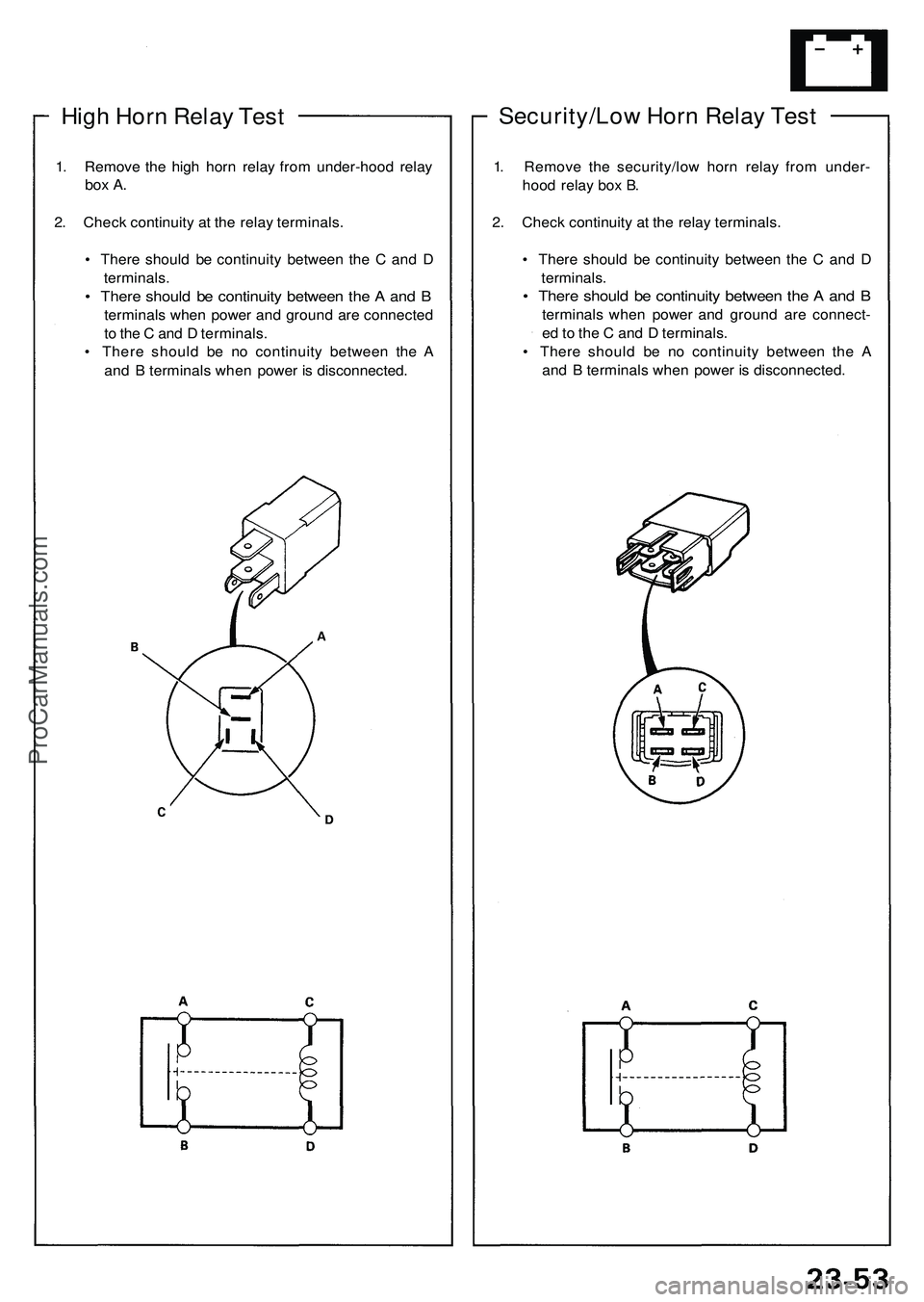
High Hor n Rela y Tes t
1. Remov e th e hig h hor n rela y fro m under-hoo d rela y
box A .
2. Chec k continuit y a t th e rela y terminals .
• Ther e shoul d b e continuit y betwee n th e C an d D
terminals .
• Ther e shoul d b e continuit y betwee n th e A an d B
terminal s whe n powe r an d groun d ar e connecte d
t o th e C an d D terminals .
• Ther e shoul d b e n o continuit y betwee n th e A
an d B terminal s whe n powe r i s disconnected .
Security/Low Hor n Rela y Tes t
1. Remov e th e security/lo w hor n rela y fro m under -
hoo d rela y bo x B .
2 . Chec k continuit y a t th e rela y terminals .
• Ther e shoul d b e continuit y betwee n th e C an d D
terminals .
• Ther e shoul d b e continuit y betwee n th e A an d B
terminal s whe n powe r an d groun d ar e connect -
e d to th e C an d D terminals .
• Ther e shoul d b e n o continuit y betwee n th e A
an d B terminal s whe n powe r i s disconnected .
ProCarManuals.com
Page 280 of 1503
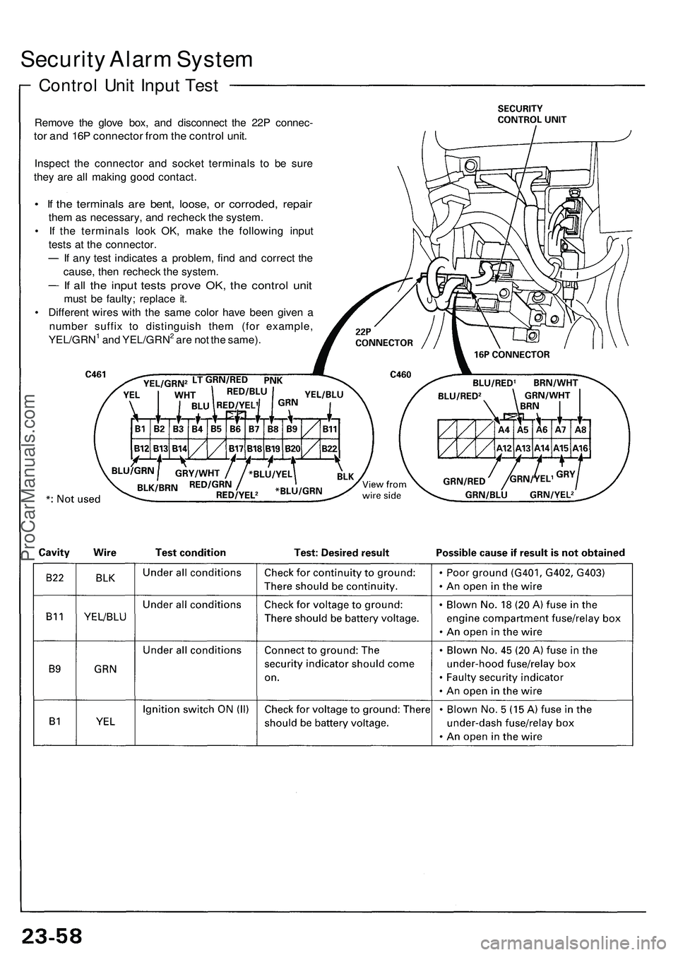
Security Alarm System
Control Unit Input Test
Remove the glove box, and disconnect the 22P connec-
tor and 16P connector from the control unit.
Inspect the connector and socket terminals to be sure
they are all making good contact.
• If the terminals are bent, loose, or corroded, repair
them as necessary, and recheck the system.
• If the terminals look OK, make the following input
tests at the connector.
If any test indicates a problem, find and correct the
cause, then recheck the system.
If all the input tests prove OK, the control unit
must be faulty; replace it.
• Different wires with the same color have been given a
number suffix to distinguish them (for example,
YEL/GRN1 and YEL/GRN2 are not the same).ProCarManuals.com