ACURA NSX 1997 Service Repair Manual
Manufacturer: ACURA, Model Year: 1997, Model line: NSX, Model: ACURA NSX 1997Pages: 1503, PDF Size: 57.08 MB
Page 281 of 1503
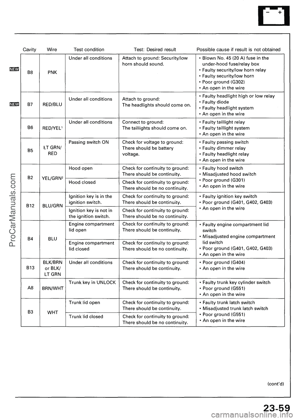
Cavity Wire Test condition Test: Desired result Possible cause if result is not obtainedProCarManuals.com
Page 282 of 1503
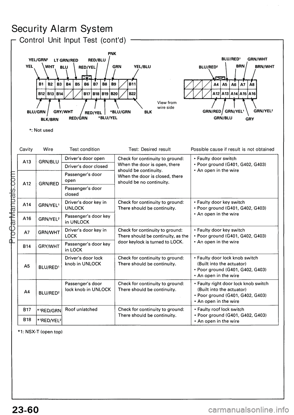
Security Alar m Syste m
Contro l Uni t Inpu t Tes t (cont'd )
Cavity Wir e Tes t conditio n Test : Desire d resul t Possibl e caus e if resul t i s no t obtaine d
ProCarManuals.com
Page 283 of 1503
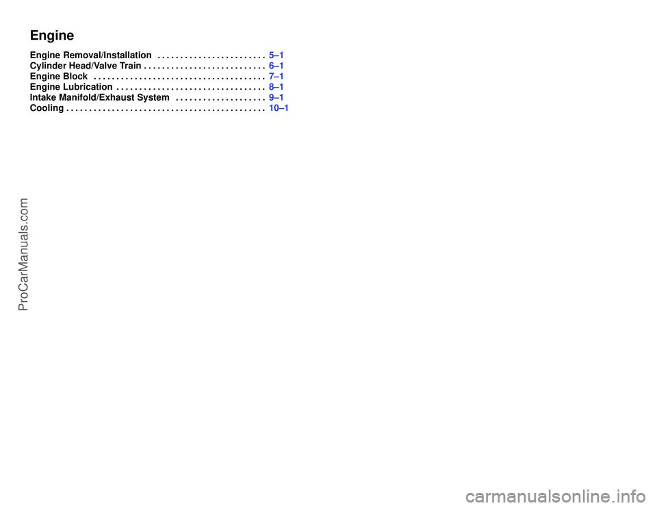
EngineEngine Removal/Installation5±1 . . . . . . . . . . . . . . . . . . . . . . . .
Cylinder Head/Valve Train6±1 . . . . . . . . . . . . . . . . . . . . . . . . . . .
Engine Block7±1 . . . . . . . . . . . . . . . . . . . . . . . . . . . . . . . . . . . . . .
Engine Lubrication8±1 . . . . . . . . . . . . . . . . . . . . . . . . . . . . . . . . .
Intake Manifold/Exhaust System9±1 . . . . . . . . . . . . . . . . . . . .
Cooling10±1 . . . . . . . . . . . . . . . . . . . . . . . . . . . . . . . . . . . . . . . . . . . .
ProCarManuals.com
Page 284 of 1503
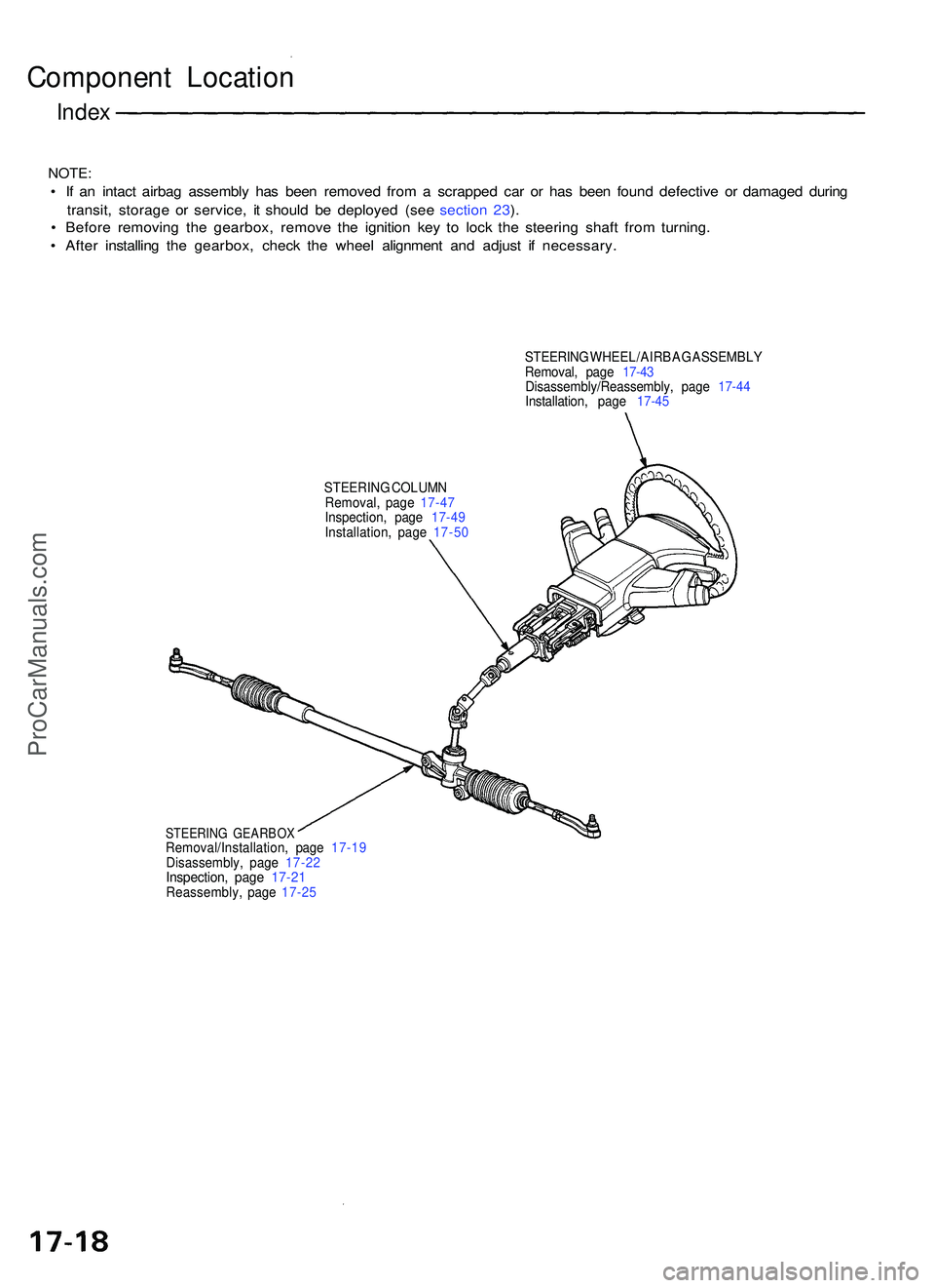
Component Locatio n
Index
NOTE :
• I f a n intac t airba g assembl y ha s bee n remove d fro m a scrappe d ca r o r ha s bee n foun d defectiv e o r damage d durin g
transit , storag e o r service , i t shoul d b e deploye d (se e sectio n 23 ).
• Befor e removin g th e gearbox , remov e th e ignitio n ke y t o loc k th e steerin g shaf t fro m turning .
• Afte r installin g th e gearbox , chec k th e whee l alignmen t an d adjus t i f necessary .
STEERING WHEEL/AIRBA G ASSEMBL Y
Removal , pag e 17-43
Disassembly/Reassembly , pag e 17- 44
Installation , pag e 17-45
STEERIN G COLUM N
Removal , pag e 17-47
Inspection , pag e 17-49
Installation , pag e 17-50
STEERIN G GEARBO XRemoval/Installation , pag e 17-1 9
Disassembly , pag e 17-2 2
Inspection , pag e 17-2 1Reassembly , pag e 17-2 5
ProCarManuals.com
Page 285 of 1503
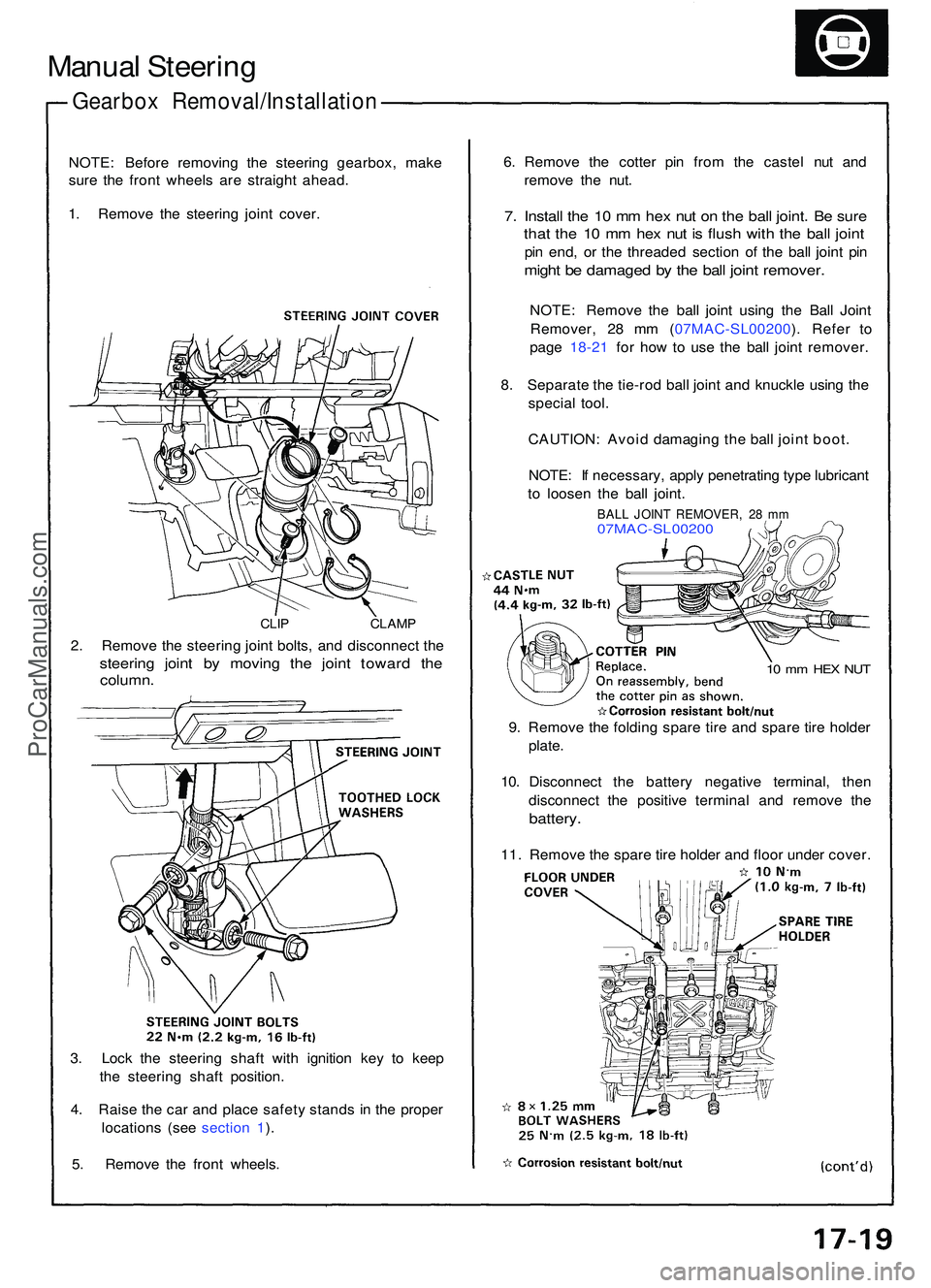
Manual Steerin g
Gearbo x Removal/Installatio n
NOTE: Befor e removin g th e steerin g gearbox , mak e
sur e th e fron t wheel s ar e straigh t ahead .
1 . Remov e th e steerin g join t cover .
CLIP CLAM P
2. Remov e th e steerin g join t bolts , an d disconnec t th e
steerin g join t b y movin g th e join t towar d th e
column .
3. Loc k th e steerin g shaf t wit h ignitio n ke y t o kee p
th e steerin g shaf t position .
4 . Rais e th e ca r an d plac e safet y stand s i n th e prope r
location s (se e sectio n 1 ).
5 . Remov e th e fron t wheels . 6
. Remov e th e cotte r pi n fro m th e caste l nu t an d
remov e th e nut .
7. Instal l th e 1 0 m m he x nu t o n th e bal l joint . B e sur e
that th e 1 0 m m he x nu t i s flus h wit h th e bal l join t
pin end , o r th e threade d sectio n o f th e bal l join t pi n
migh t b e damage d b y th e bal l join t remover .
NOTE: Remov e th e bal l join t usin g th e Bal l Join t
Remover , 2 8 m m ( 07MAC-SL00200 ). Refe r t o
pag e 18-2 1 fo r ho w to us e th e bal l join t remover .
8 . Separat e th e tie-ro d bal l join t an d knuckl e usin g th e
specia l tool .
CAUTION : Avoi d damagin g th e bal l join t boot .
NOTE : I f necessary , appl y penetratin g typ e lubrican t
t o loose n th e bal l joint .
BALL JOIN T REMOVER , 2 8 m m07MAC-SL0020 0
10 m m HE X NU T
9. Remov e th e foldin g spar e tir e an d spar e tir e holde r
plate .
10 . Disconnec t th e batter y negativ e terminal , the n
disconnec t th e positiv e termina l an d remov e th e
battery .
11. Remov e th e spar e tir e holde r an d floo r unde r cover .
ProCarManuals.com
Page 286 of 1503
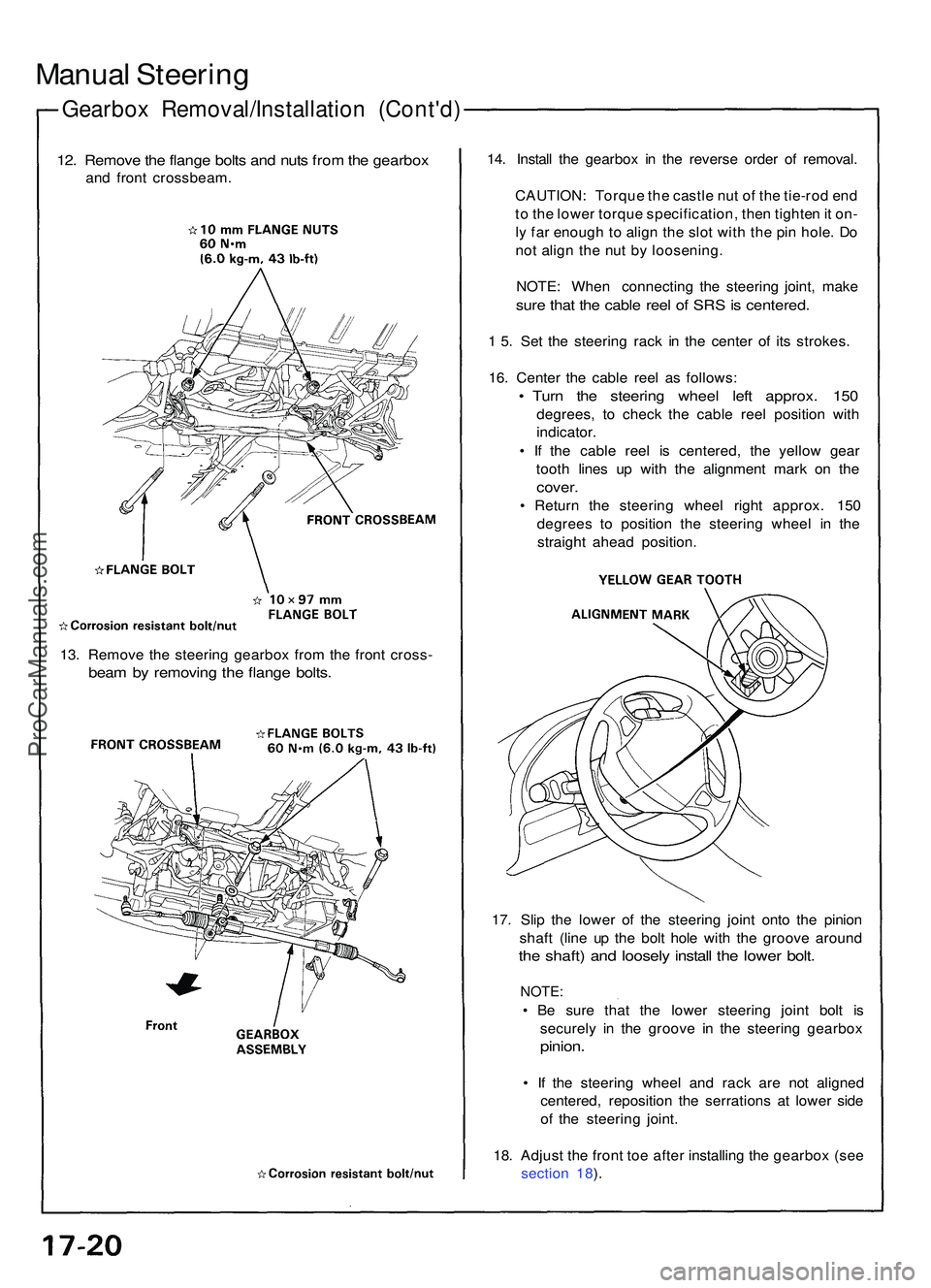
Gearbox Removal/Installatio n (Cont'd )
Manual Steerin g
12. Remov e th e flang e bolt s an d nut s fro m th e gearbo x
and fron t crossbeam . 14
. Instal l th e gearbo x i n th e revers e orde r o f removal .
CAUTION : Torqu e th e castl e nu t o f th e tie-ro d en d
t o th e lowe r torqu e specification , the n tighte n it on -
l y fa r enoug h to alig n th e slo t wit h th e pi n hole . D o
no t alig n th e nu t b y loosening .
NOTE : Whe n connectin g th e steerin g joint , mak e
sure tha t th e cabl e ree l o f SR S is centered .
1 5 . Se t th e steerin g rac k i n th e cente r o f it s strokes .
16 . Cente r th e cabl e ree l a s follows :
• Tur n th e steerin g whee l lef t approx . 15 0
degrees , t o chec k th e cabl e ree l positio n wit h
indicator .
• I f th e cabl e ree l i s centered , th e yello w gea r
toot h line s u p wit h th e alignmen t mar k o n th e
cover .
• Retur n th e steerin g whee l righ t approx . 15 0
degree s t o positio n th e steerin g whee l i n th e
straigh t ahea d position .
17 . Sli p th e lowe r o f th e steerin g join t ont o th e pinio n
shaf t (lin e u p th e bol t hol e wit h th e groov e aroun d
the shaft ) an d loosel y instal l th e lowe r bolt .
NOTE :
• B e sur e tha t th e lowe r steerin g join t bol t i s
securel y i n th e groov e i n th e steerin g gearbo x
pinion.
• I f th e steerin g whee l an d rac k ar e no t aligne d
centered , repositio n th e serration s a t lowe r sid e
of th e steerin g joint .
18 . Adjus t th e fron t to e afte r installin g th e gearbo x (se e
sectio n 18 ).
13
. Remov e th e steerin g gearbo x fro m th e fron t cross -
beam b y removin g th e flang e bolts .
ProCarManuals.com
Page 287 of 1503
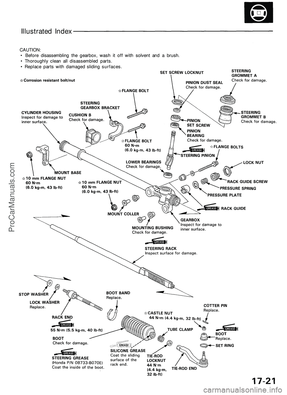
CAUTION:
• Before disassembling the gearbox, wash it off with solvent and a brush.
• Thoroughly clean all disassembled parts.
• Replace parts with damaged sliding surfaces.
Illustrated IndexProCarManuals.com
Page 288 of 1503
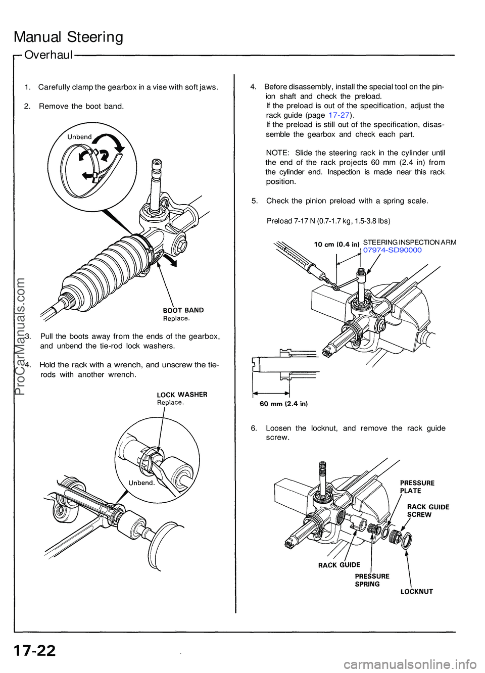
Overhaul
Manual Steerin g
1. Carefull y clam p th e gearbo x in a vis e wit h sof t jaws .
2 . Remov e th e boo t band . 4
. Befor e disassembly , instal l th e specia l too l o n th e pin -
io n shaf t an d chec k th e preload .
I f th e preloa d i s ou t o f th e specification , adjus t th e
rac k guid e (pag e 17-27 ).
I f th e preloa d i s stil l ou t o f th e specification , disas -
sembl e th e gearbo x an d chec k eac h part .
NOTE : Slid e th e steerin g rac k i n th e cylinde r unti l
th e en d o f th e rac k project s 6 0 m m (2. 4 in ) fro m
th e cylinde r end . Inspectio n i s mad e nea r thi s rac k
position .
5. Chec k th e pinio n preloa d wit h a sprin g scale .
Preload 7-17 N (0.7-1.7 kg, 1.5-3.8 Ibs)
STEERIN G INSPECTIO N AR M07974-SD9000 0
3. Pul l th e boot s awa y fro m th e end s o f th e gearbox ,
an d unben d th e tie-ro d loc k washers .
4. Hol d th e rac k wit h a wrench , an d unscre w th e tie -
rod s wit h anothe r wrench .
6. Loose n th e locknut , an d remov e th e rac k guid e
screw .
ProCarManuals.com
Page 289 of 1503
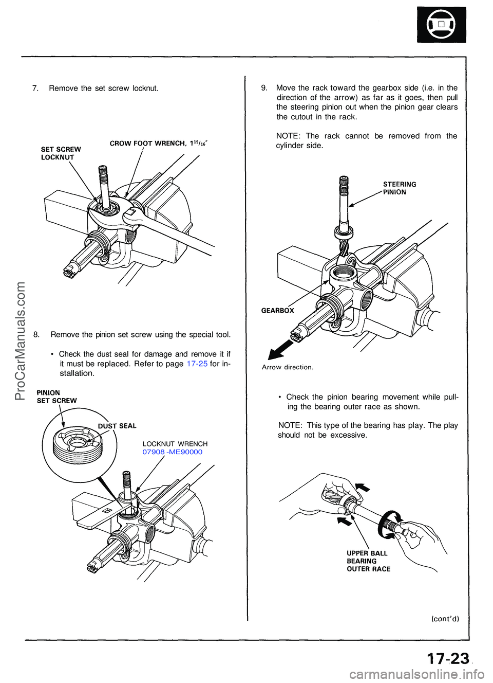
7. Remov e th e se t scre w locknut . 9
. Mov e th e rac k towar d th e gearbo x sid e (i.e . i n th e
directio n o f th e arrow ) a s fa r a s i t goes , the n pul l
th e steerin g pinio n ou t whe n th e pinio n gea r clear s
th e cutou t i n th e rack .
NOTE : Th e rac k canno t b e remove d fro m th e
cylinde r side .
8 . Remov e th e pinio n se t scre w usin g th e specia l tool .
• Chec k th e dus t sea l fo r damag e an d remov e i t i f
i t mus t b e replaced . Refe r t o pag e 17-2 5 fo r in -
stallation .
• Chec k th e pinio n bearin g movemen t whil e pull -
in g th e bearin g oute r rac e a s shown .
NOTE : Thi s typ e o f th e bearin g ha s play . Th e pla y
shoul d no t b e excessive .
LOCKNUT WRENC H07908 -ME9000 0
ProCarManuals.com
Page 290 of 1503
Overhaul (Cont'd )
Manual Steerin g
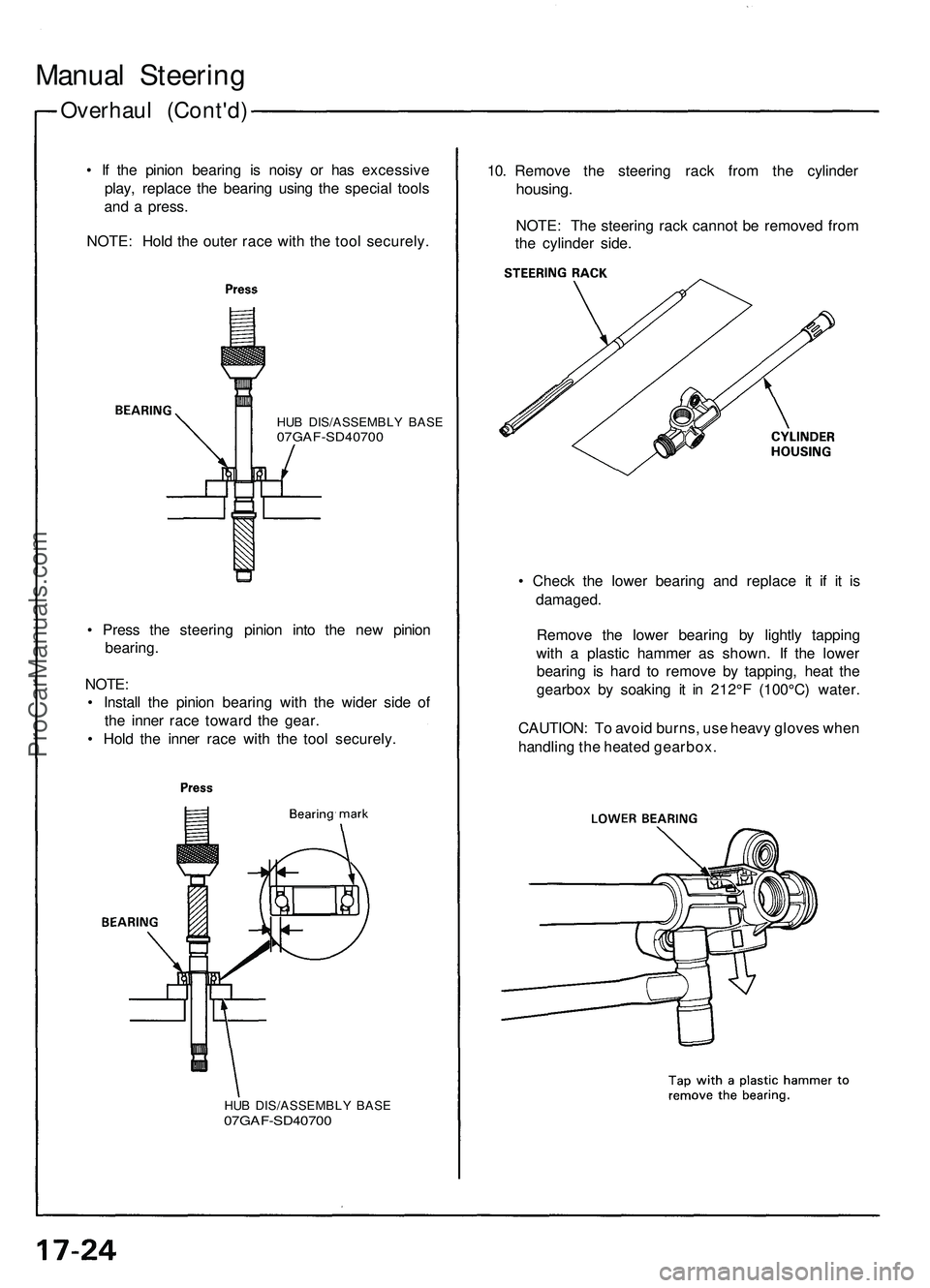
• I f th e pinio n bearin g i s nois y o r ha s excessiv e
play , replac e th e bearin g usin g th e specia l tool s
an d a press .
NOTE : Hol d th e oute r rac e wit h th e too l securely .10
. Remov e th e steerin g rac k fro m th e cylinde r
housing.
NOTE: Th e steerin g rac k canno t b e remove d fro m
th e cylinde r side .
HUB DIS/ASSEMBL Y BAS E07GAF-SD4070 0
• Chec k th e lowe r bearin g an d replac e i t i f i t i s
damaged .
Remov e th e lowe r bearin g b y lightl y tappin g
with a plasti c hamme r a s shown . I f th e lowe r
bearin g i s har d t o remov e b y tapping , hea t th e
gearbo x b y soakin g i t i n 212° F (100°C ) water .
CAUTION : T o avoi d burns , us e heav y glove s whe n
handlin g th e heate d gearbox .
•
Pres s th e steerin g pinio n int o th e ne w pinio n
bearing .
NOTE :
• Instal l th e pinio n bearin g wit h th e wide r sid e of
th e inne r rac e towar d th e gear .
• Hol d th e inne r rac e wit h th e too l securely .
HUB DIS/ASSEMBL Y BAS E07GAF-SD4070 0
ProCarManuals.com