ACURA NSX 1997 Service Repair Manual
Manufacturer: ACURA, Model Year: 1997, Model line: NSX, Model: ACURA NSX 1997Pages: 1503, PDF Size: 57.08 MB
Page 871 of 1503
Bearing Preload
Adjustment
NOTE: If any of the items listed below are replaced, the
bearing preload must be adjusted.
TRANSMISSION HOUSING
TORQUE CONVERTER HOUSING
DIFFERENTIAL
TAPERED ROLLER BEARING and OUTER RACE
75 mm THRUST SHIM
90 mm WASHER
OIL GUIDE RING
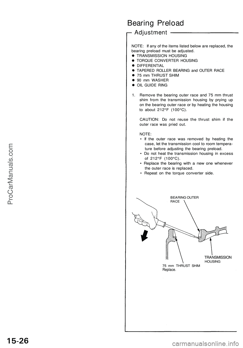
1. Remove the bearing outer race and 75 mm thrust
shim from the transmission housing by prying up
on the bearing outer race or by heating the housing
to about 212°F (100°C).
CAUTION: Do not reuse the thrust shim if the
outer race was pried out.
NOTE:
• If the outer race was removed by heating the
case, let the transmission cool to room tempera-
ture before adjusting the bearing preload.
• Do not heat the transmission housing in excess
of 212°F (100°C).
• Replace the bearing with a new one whenever
the outer race is replaced.
• Repeat on the torque converter side.
BEARING OUTER
RACE
TRANSMISSION
HOUSING
75 mm THRUST SHIM
Replace.ProCarManuals.com
Page 872 of 1503
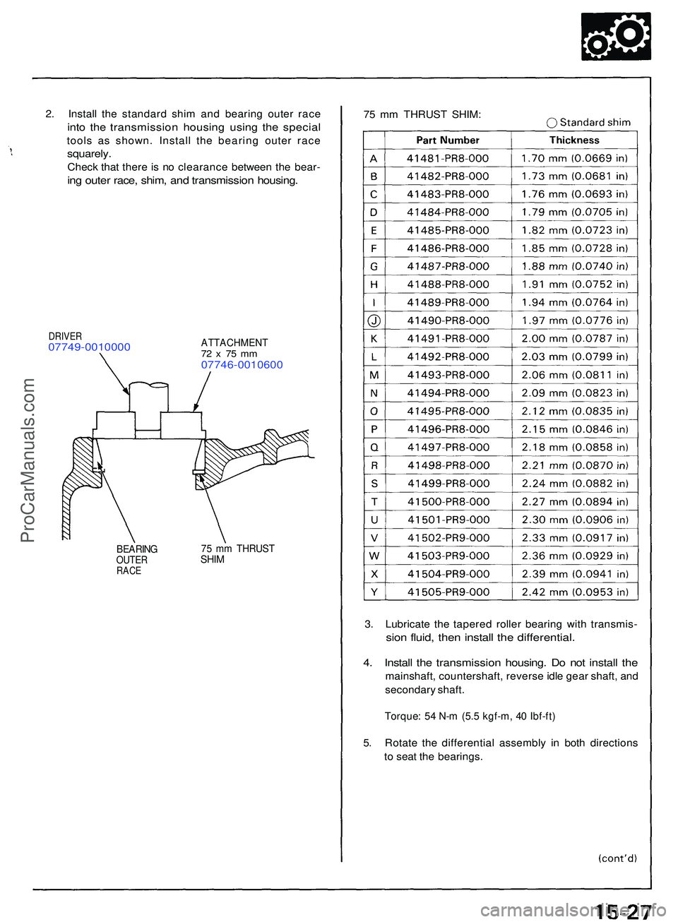
2. Instal l th e standar d shi m an d bearin g oute r rac e
into th e transmissio n housin g usin g th e specia l
tools a s shown . Instal l th e bearin g oute r rac e
squarely .
Check tha t ther e is n o clearanc e betwee n th e bear -
ing oute r race , shim , an d transmissio n housing .
75 m m THRUS T SHIM :
ATTACHMEN T72 x 7 5 m m07746-001060 0
DRIVER07749-001000 0
BEARINGOUTERRACE
75 m m THRUS TSHIM
3. Lubricat e th e tapere d rolle r bearin g wit h transmis -
sion fluid , the n instal l th e differential .
4. Instal l th e transmissio n housing . D o no t instal l th e
mainshaft , countershaft , revers e idl e gea r shaft , an d
secondar y shaft .
Torque : 5 4 N- m (5. 5 kgf-m , 4 0 Ibf-ft )
5. Rotat e th e differentia l assembl y i n bot h direction s
t o sea t th e bearings .
ProCarManuals.com
Page 873 of 1503
Bearing Preloa d
Adjustmen t (cont'd )
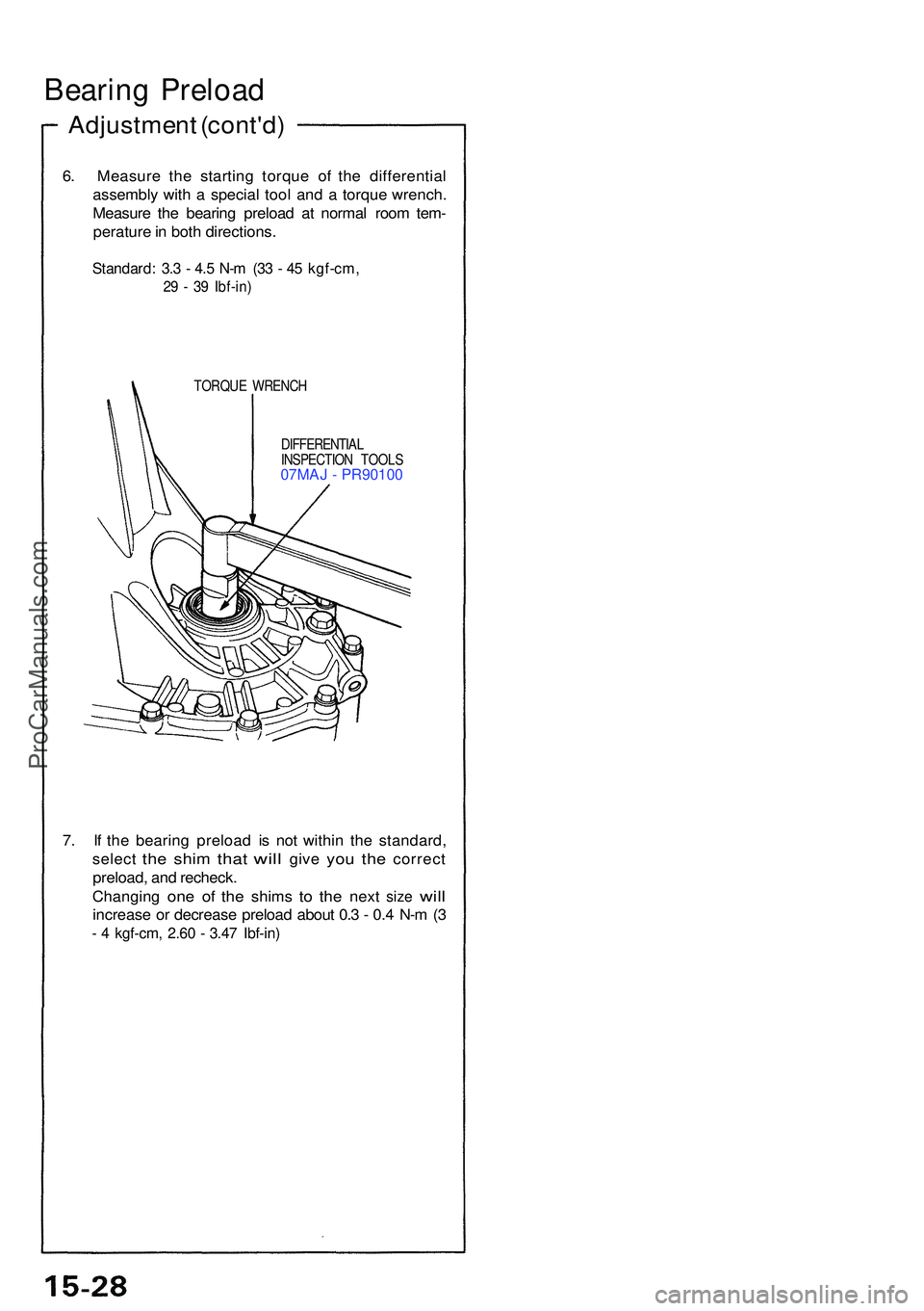
6. Measur e th e startin g torqu e o f th e differentia l
assembl y wit h a specia l too l an d a torqu e wrench .
Measur e th e bearin g preloa d a t norma l roo m tem -
peratur e in bot h directions .
Standard: 3. 3 - 4. 5 N- m (3 3 - 4 5 kgf-cm ,
29 - 3 9 Ibf-in )
TORQU E WRENC H
DIFFERENTIA L
INSPECTIO N TOOL S
07MAJ - PR90100
7. I f th e bearin g preloa d i s no t withi n th e standard ,
selec t
the shi m tha t will giv e you th e correc t
preload , an d recheck .
Changin g
one o f th e shim s to th e nex t size will
increas e o r decreas e preloa d abou t 0. 3 - 0. 4 N- m (3
- 4 kgf-cm , 2.6 0 - 3.4 7 Ibf-in )
ProCarManuals.com
Page 874 of 1503
Oil Seal
Installation
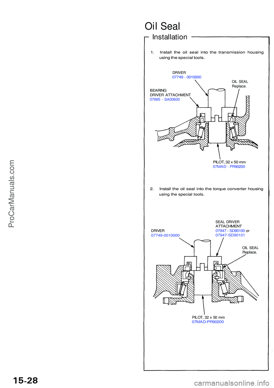
1. Instal l th e oi l sea l int o th e transmissio n housin g
usin g th e specia l tools .
DRIVE R07749 - 001000 0OIL SEA LReplace .BEARINGDRIVER ATTACHMEN T07965 - SA0060 0
PILOT, 3 2 x 50 m m
07MA D - PR9020 0
2. Instal l th e oi l sea l int o th e torqu e converte r housin g
using th e specia l tools .
DRIVE R07749-001000 0
SEAL DRIVE RATTACHMEN T
0794 7 - SD9010 0 o r
07947-SD9010 1
OIL SEA LReplace .
PILOT, 3 2 x 50 m m07MAD-PR9020 0
ProCarManuals.com
Page 875 of 1503
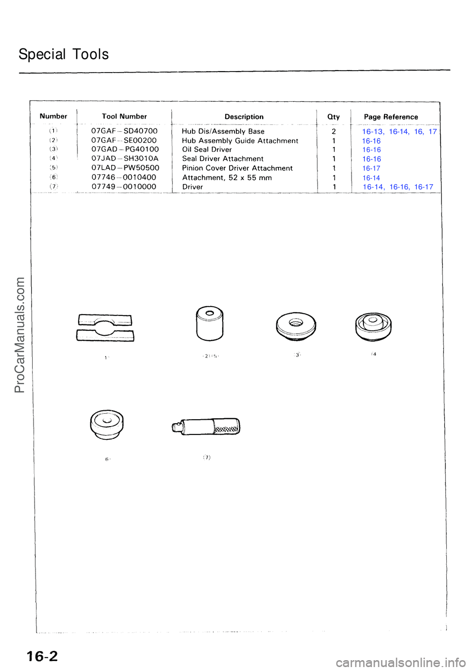
Special Tool s
16-13 , 16-14 , 16 , 1 7
16-1 6
16-1 6
16-16
16-1 7
16-1 4
16-14 , 16-16 , 16-1 7
ProCarManuals.com
Page 876 of 1503
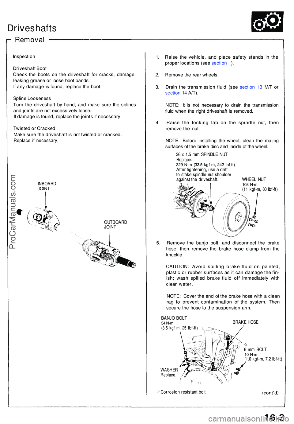
Driveshafts
Inspection
Driveshaf t Boo t
Chec k th e boot s o n th e driveshaf t fo r cracks , damage ,
leakin g greas e o r loos e boo t bands .
I f an y damag e i s found , replac e th e boo t
Splin e Loosenes s
Turn th e driveshaf t b y hand , an d mak e sur e th e spline s
an d joint s ar e no t excessivel y loose .
I f damag e is found , replac e th e joint s i f necessary .
Twiste d o r Cracked
Mak e sur e th e driveshaf t i s not twiste d o r cracked .
Replace i f necessary .
INBOARDJOINT
OUTBOAR DJOINT
1. Rais e th e vehicle , an d plac e safet y stand s i n th e
prope r location s (se e sectio n 1 ).
2 . Remov e th e rea r wheels .
3 . Drai n th e transmissio n flui d (se e sectio n 1 3 M/ T o r
sectio n 1 4 A/T) .
NOTE : I t i s no t necessar y t o drai n th e transmissio n
flui d whe n th e righ t driveshaf t i s removed .
4 . Rais e th e lockin g ta b o n th e spindl e nut , the n
remov e th e nut .
NOTE : Befor e installin g th e wheel , clea n th e matin g
surface s o f th e brak e dis c an d insid e o f th e wheel .
26 x 1. 5 m m SPINDL E NU TReplace .329 N- m (33. 5 kgf m , 24 2 Ib f ft )Afte r tightening , us e a drif tto stak e spindl e nu t shoulde ragainst th e driveshaft . WHEE L NU T108 N- m(11 kgf-m , 8 0 Ibf-ft )
5. Remov e th e banj o bolt , an d disconnec t th e brak e
hose , the n remov e th e brak e hos e clam p fro m th e
knuckle .
CAUTION : Avoi d spillin g brak e flui d o n painted ,
plasti c o r rubbe r surface s a s i t ca n damag e th e fin -
ish ; was h spille d brak e flui d of f immediatel y wit h
clea n water .
NOTE : Cove r th e en d o f th e brak e hos e wit h a clea n
ra g t o preven t contaminatio n o f th e system . The n
secur e th e hos e t o th e suspensio n arm .
BANJ O BOL T34 N-m(3.5 kg f m , 2 5 Ibf-ft )
WASHE RReplace .
Corrosio n resistan t bol t
BRAK E HOS E
6 m m BOL T10 N- m(1.0 kgf-m , 7. 2 Ibf-ft )
Remova l
ProCarManuals.com
Page 877 of 1503
Driveshafts
Removal
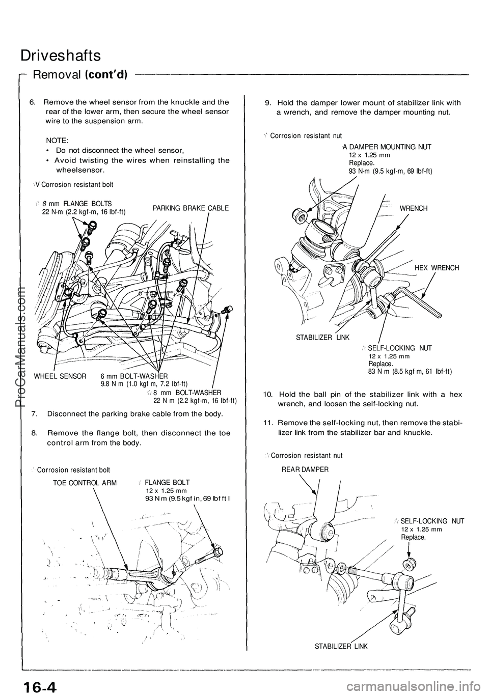
6. Remove the wheel sensor from the knuckle and the
rear of the lower arm, then secure the wheel sensor
wire to the suspension arm.
NOTE:
• Do not disconnect the wheel sensor,
• Avoid twisting the wires when reinstalling the
wheel sensor.
V Corrosion resistant bolt
8 mm FLANGE BOLTS
22 N-m (2.2 kgf-m, 16 Ibf-ft)
PARKING BRAKE CABLE
WHEEL SENSOR 6 mm BOLT-WASHER
9.8 N m (1.0 kgf m, 7.2 Ibf-ft)
8 mm BOLT-WASHER
22 N m (2.2 kgf-m, 16 Ibf-ft)
7. Disconnect the parking brake cable from the body.
8. Remove the flange bolt, then disconnect the toe
control arm from the body.
Corrosion resistant bolt
TOE CONTROL ARM
FLANGE BOLT
12 x
1.25
mm
93 N m
(9.5
kgf in, 69 Ibf ft I
9. Hold the damper lower mount of stabilizer link with
a wrench, and remove the damper mounting nut.
Corrosion resistant nut
A DAMPER MOUNTING NUT
12 x
1.25
mm
Replace.
93 N-m (9.5 kgf-m, 69 Ibf-ft)
WRENCH
HEX WRENCH
STABILIZER LINK
SELF-LOCKING NUT
12 x
1.25
mm
Replace.
83 N m (8.5 kgf m, 61 Ibf-ft)
10. Hold the ball pin of the stabilizer link with a hex
wrench, and loosen the self-locking nut.
11. Remove the self-locking nut, then remove the stabi-
lizer link from the stabilizer bar and knuckle.
Corrosion resistant nut
REAR DAMPER
SELF-LOCKING NUT
12 x
1.25
mm
Replace.
STABILIZER LINKProCarManuals.com
Page 878 of 1503
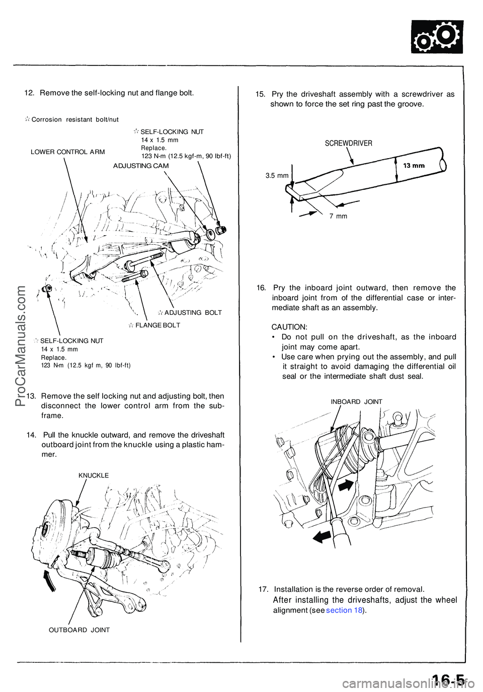
12. Remov e th e self-lockin g nu t an d flang e bolt .
Corrosio n resistan t bolt/nu t
LOWE R CONTRO L AR M SELF-LOCKIN
G NU T
14 x 1. 5 m mReplace .123 N- m (12. 5 kgf-m , 9 0 Ibf-ft )
ADJUSTIN G CA M
ADJUSTIN G BOL T
FLANG E BOL T
SELF-LOCKIN G NU T
14 x 1. 5 m mReplace .123 N- m (12. 5 kg f m , 9 0 Ibf-ft )
13. Remov e th e sel f lockin g nu t an d adjustin g bolt , the n
disconnec t th e lowe r contro l ar m fro m th e sub -
frame .
14. Pul l th e knuckl e outward , an d remov e th e driveshaf t
outboar d join t fro m th e knuckl e usin g a plasti c ham -
mer.
KNUCKL E
OUTBOAR D JOIN T
15. Pr y th e driveshaf t assembl y wit h a screwdrive r a s
show n to forc e th e se t rin g pas t th e groove .
SCREWDRIVE R
3.5 m m
7 m m
16. Pr y th e inboar d join t outward , the n remov e th e
inboar d join t fro m o f th e differentia l cas e o r inter -
mediat e shaf t a s a n assembly .
CAUTION :
• D o no t pul l o n th e driveshaft , a s th e inboar d
join t ma y com e apart .
• Us e car e whe n pryin g ou t th e assembly , an d pul l
i t straigh t t o avoi d damagin g th e differentia l oi l
sea l o r th e intermediat e shaf t dus t seal .
INBOAR D JOIN T
17. Installatio n is th e revers e orde r o f removal .
After installin g th e driveshafts , adjus t th e whee l
alignmen t (se e sectio n 18 ).
ProCarManuals.com
Page 879 of 1503
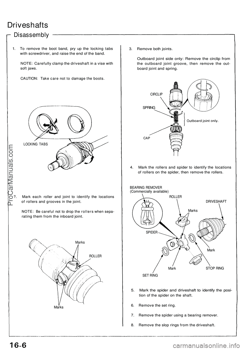
Driveshafts
Disassembly
1. To remove the boot band, pry up the locking tabs
with screwdriver, and raise the end of the band.
NOTE: Carefully clamp the driveshaft in a vise with
soft jaws.
CAUTION: Take care not to damage the boots.
LOCKING TABS
?. Mark each roller and joint to identify the locations
of rollers and grooves in the joint.
NOTE: Be careful not to drop the rollers when sepa-
rating them from the inboard joint.
Marks
ROLLER
Marks
3. Remove both joints.
Outboard joint side only: Remove the circlip from
the outboard joint groove, then remove the out-
board joint and spring.
CIRCLIP
SPRING
CAP
4. Mark the rollers and spider to identify the locations
of rollers on the spider, then remove the rollers.
BEARING REMOVER
(Commercially available)
ROLLER
DRIVESHAFT
Mark
STOP RING
SET RING
5. Mark the spider and driveshaft to identify the posi-
tion of the spider on the shaft.
6. Remove the set ring.
7. Remove the spider using a bearing remover.
8. Remove the slop rings from the driveshaft.
SPIDER
Marks
MarkProCarManuals.com
Page 880 of 1503
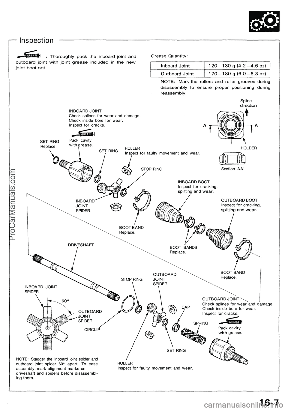
Inspection
: Thoroughl y pac k th e inboar d join t an d
outboar d join t wit h join t greas e include d i n th e ne w
joint boo t set .
Greas e Quantity :
NOTE: Mar k th e roller s an d rolle r groove s durin g
disassembl y t o ensur e prope r positionin g durin g
reassembly .
Splinedirectio n
INBOAR D JOIN T
Chec k spline s fo r wea r an d damage .
Chec k insid e bor e fo r wear .
Inspec t fo r cracks .
SE T RIN G
Replace .
Pack cavit ywith grease .
SET RIN GROLLE RInspect fo r fault y movemen t an d wear .HOLDE R
STOP RIN G Sectio
n AA '
INBOAR D BOO T
Inspec t fo r cracking ,
splitting an d wear .
OUTBOAR D BOO TInspec t fo r cracking ,splitting an d wear .
OUTBOAR D JOIN T
Chec k spline s fo r wea r an d damage .
Chec k insid e bor e fo r wear .
Inspec t fo r cracks .
NOTE: Stagge r th e inboar d join t spide r an d
outboar d join t spide r 60 ° apart . T o eas e
assembly , mar k alignmen t mark s o n
driveshaf t an d spider s befor e disassembl -
ing them .
ROLLE RInspect fo r fault y movemen t an d wear .
INBOAR
D
JOINTSPIDE R
BOOT BAN DReplace .
BOOT BAND S
Replace .
BOOT BAN D
Replace .
DRIVESHAF T
STOP RIN G OUTBOAR
DJOINTSPIDE R
CAP
SPRIN G
SE T RIN G
CIRCLI P
OUTBOAR DJOINTSPIDE R
INBOAR D JOIN TSPIDE R
ProCarManuals.com