ACURA RL KA9 1996 Service Repair Manual
Manufacturer: ACURA, Model Year: 1996, Model line: RL KA9, Model: ACURA RL KA9 1996Pages: 1954, PDF Size: 61.44 MB
Page 1311 of 1954
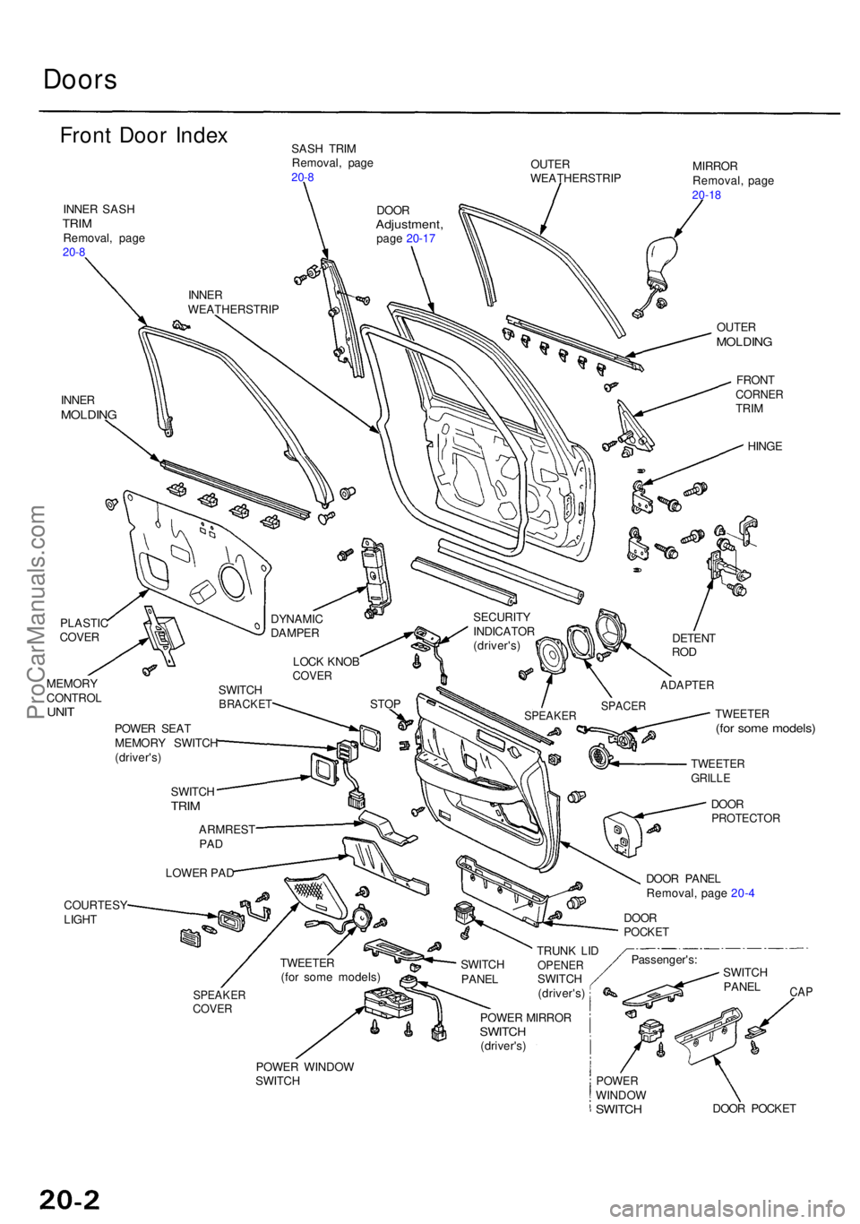
Doors
Front Doo r Inde xSASH TRI M
Removal , pag e
20-8OUTE RWEATHERSTRI PMIRRORRemoval , pag e20-18INNE R SAS HTRIMRemoval , pag e20-8
INNE RMOLDIN G
OUTERMOLDIN G
FRONTCORNE RTRIM
HING E
PLASTI C
COVER
MEMOR Y
CONTRO L
UNITTWEETE R(for som e models )
COURTES Y
LIGH T
SPEAKE RCOVER
CAP
POWE R WINDO W
SWITC HPOWERWINDO WSWITCHDOOR POCKE T
LOWE
R PA D
ARMRES
T
PAD
SWITC HTRIM
POWE R SEA T
MEMOR Y SWITC H
(driver's )
POWER MIRRO R
SWITCH(driver's )TRUN
K LI D
OPENE RSWITCH
(driver's ) Passenger's
:
SWITC HPANEL
SWITC HPANEL
DOORPOCKE T
DOOR PANE L
Removal , pag e 20- 4
DOO
R
PROTECTO R
TWEETERGRILLE
TWEETE R(for som e models )
STO
P
LOC
K KNO B
COVE R
DYNAMI CDAMPER
SWITCHBRACKE TSPEAKERSPACER
ADAPTE R
DETENTROD
SECURIT Y
INDICATO R
(driver's )
INNE
R
WEATHERSTRI P
DOORAdjustment ,page 20-1 7
ProCarManuals.com
Page 1312 of 1954
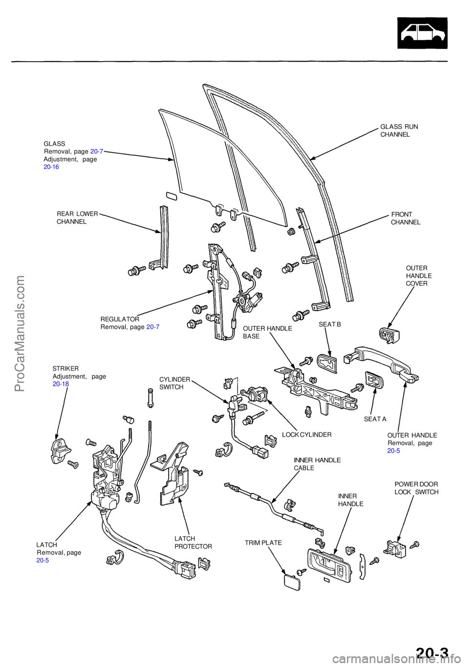
GLASSRemoval , pag e 20- 7
Adjustment , pag e
20-16
REA R LOWE RCHANNE L
STRIKERAdjustment , pag e20-18
GLAS S RU N
CHANNE L
FRON T
CHANNE L
OUTERHANDL E
COVE R
OUTE R HANDL E
Removal , pag e
20-5
POWE R DOO R
LOC K SWITC H
LATCHRemoval , pag e20-5
REGULATO RRemoval, pag e 20- 7
CYLINDE RSWITCH OUTE
R HANDL E
BASE
SEAT B
SEAT A
LOC K CYLINDE R
INNER HANDL ECABLE
INNER
HANDL E
TRI M PLAT E
LATCHPROTECTO R
ProCarManuals.com
Page 1313 of 1954
Doors
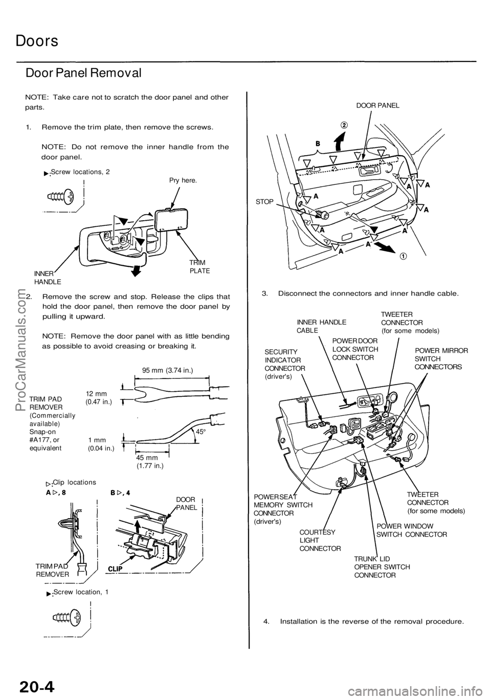
Door Pane l Remova l
NOTE: Tak e car e no t t o scratc h th e doo r pane l an d othe r
parts.
1. Remov e th e tri m plate , the n remov e th e screws .
NOTE : D o no t remov e th e inne r handl e fro m th e
doo r panel .
Screw locations , 2
Pry here .
INNE R
HANDL E TRI
M
PLAT E
2. Remov e th e scre w an d stop . Releas e th e clip s tha t
hol d th e doo r panel , the n remov e th e doo r pane l b y
pullin g it upward .
NOTE: Remov e th e doo r pane l wit h a s littl e bendin g
a s possibl e to avoi d creasin g o r breakin g it .
TRI M PA DREMOVE R(Commerciall yavailable)Snap-on
#A177 , o r
equivalen t
12 m m(0.4 7 in. )
1 m m(0.0 4 in. )
45 m m(1.7 7 in. )
Clip location s
DOORPANE L
TRIM PA DREMOVE R
DOOR PANE L
STO P
3. Disconnec t th e connector s an d inne r handl e cable .
SECURIT YINDICATO R
CONNECTO R
(driver's )
POWE R SEA T
MEMOR Y SWITC H
CONNECTO R
(driver's)
COURTES YLIGHT
CONNECTO R
TWEETERCONNECTO R(for som e models )
POWER WINDO W
SWITC H CONNECTO R
TRUN K LI D
OPENE R SWITC H
CONNECTO R
4. Installatio n i s th e revers e o f th e remova l procedure .
INNER HANDL ECABLE
POWE R DOO R
LOC K SWITC H
CONNECTO RTWEETE
R
CONNECTO R
(fo r som e models )
POWE R MIRRO R
SWITC H
CONNECTOR S
Screw location , 1
9 5 m m (3.7 4 in. )
45°
ProCarManuals.com
Page 1314 of 1954
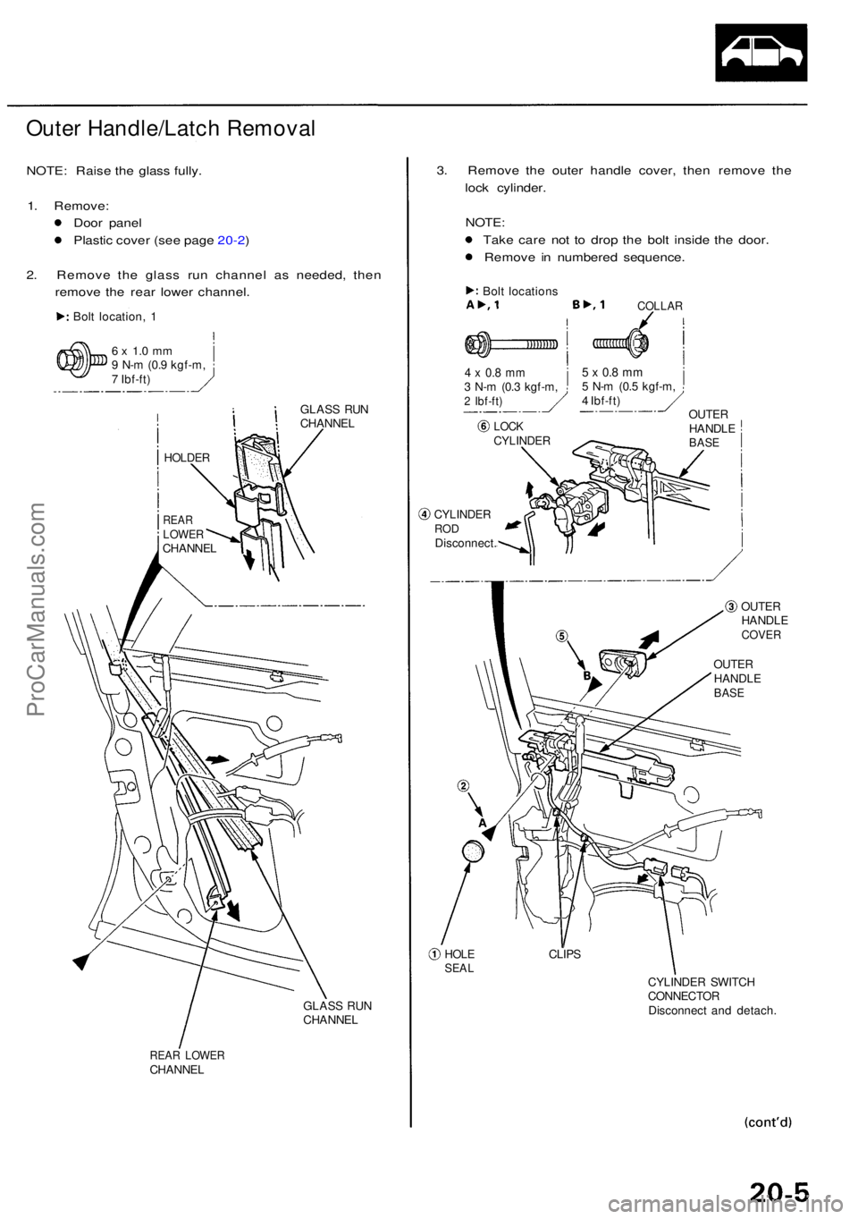
Outer Handle/Latc h Remova l
NOTE: Rais e th e glas s fully .
1 . Remove :
Doo r pane l
Plasti c cove r (se e pag e 20-2 )
2 . Remov e th e glas s ru n channe l a s needed , the n
remov e th e rea r lowe r channel .
Bolt location , 1
6 x 1. 0 m m9 N- m (0. 9 kgf-m ,
7 Ibf-ft )
GLASS RU N
CHANNE L
GLAS S RU N
CHANNE L
REAR LOWE RCHANNE L
3. Remov e th e oute r handl e cover , the n remov e th e
loc k cylinder .
NOTE :
Tak e car e no t t o dro p th e bol t insid e th e door .
Remov e i n numbere d sequence .
Bolt location s
4 x 0. 8 m m3 N- m (0. 3 kgf-m ,2 Ibf-ft )
CYLINDE RRODDisconnect .
COLLAR
5 x 0. 8 m m5 N- m (0. 5 kgf-m ,
4 Ibf-ft )
OUTE RHANDL EBASE
HOLESEA L
OUTE RHANDL ECOVER
OUTERHANDL EBASE
CLIP S
CYLINDE R SWITC H
CONNECTO R
Disconnec t an d detach .
LOCKCYLINDE R
HOLDER
REARLOWE RCHANNE L
ProCarManuals.com
Page 1315 of 1954
Doors
Outer Handle/Latc h Remova l (cont'd )
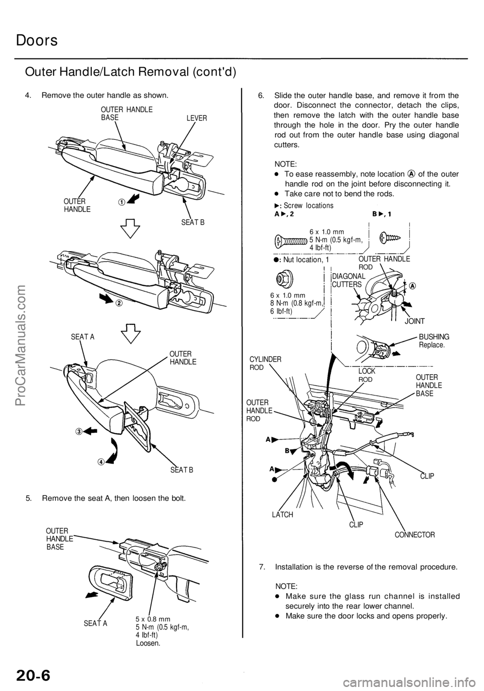
4. Remov e th e oute r handl e a s shown .
OUTER HANDL EBASELEVE R
SEAT B
5. Remov e th e sea t A , the n loose n th e bolt .
OUTE RHANDL EBASE
SEAT A5 x 0. 8 m m5 N- m (0. 5 kgf-m ,
4 Ibf-ft )
Loosen .
6. Slid e th e oute r handl e base , an d remov e i t fro m th e
door . Disconnec t th e connector , detac h th e clips ,
the n remov e th e latc h wit h th e oute r handl e bas e
throug h th e hol e i n th e door . Pr y th e oute r handl e
ro d ou t fro m th e oute r handl e bas e usin g diagona l
cutters .
NOTE:
To eas e reassembly , not e locatio n o f th e oute r
handl e ro d o n th e join t befor e disconnectin g it .
Tak e car e no t t o ben d th e rods .
Screw location s
6 x 1. 0 m m5 N- m (0. 5 kgf-m ,
4 Ibf-ft )
Nut location , 1OUTE R HANDL EROD
DIAGONA L
CUTTER S
6 x 1. 0 m m8 N- m (0. 8 kgf-m ,6 Ibf-ft )
CYLINDE RROD
OUTE R
HANDL E
ROD
BUSHIN GReplace .
OUTE R
HANDL E
BASE
CLIP
LATC H
CLIP
CONNECTO R
7. Installatio n i s th e revers e o f th e remova l procedure .
NOTE:
Make sur e th e glas s ru n channe l i s installe d
securel y int o th e rea r lowe r channel .
Mak e sur e th e doo r lock s an d open s properly .
SEAT B
OUTE
R
HANDL E
OUTERHANDL E
SEAT A
LOC KROD
JOIN T
ProCarManuals.com
Page 1316 of 1954
Glass/Regulator Remova l
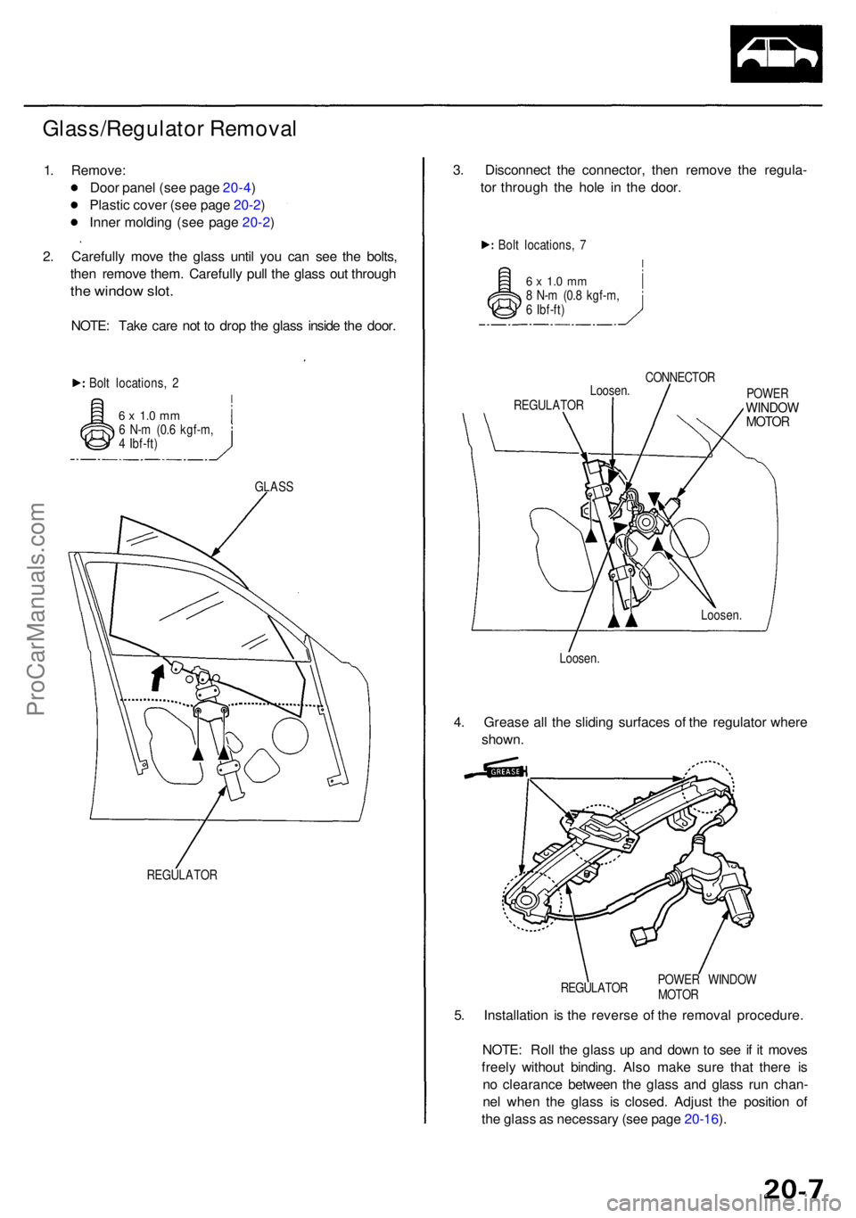
1. Remove :
Doo r pane l (se e pag e 20-4 )
Plasti c cove r (se e pag e 20-2 )
Inne r moldin g (se e pag e 20-2 )
2 . Carefull y mov e th e glas s unti l yo u ca n se e th e bolts ,
the n remov e them . Carefull y pul l th e glas s ou t throug h
the windo w slot .
NOTE : Tak e car e no t t o dro p th e glas s insid e th e door .
Bolt locations , 2
6 x 1. 0 m m6 N- m (0. 6 kgf-m ,
4 Ibf-ft )
GLASS
REGULATO R
3. Disconnec t th e connector , the n remov e th e regula -
to r throug h th e hol e i n th e door .
Bolt locations , 7
6 x 1. 0 m m8 N- m (0. 8 kgf-m ,
6 Ibf-ft )
CONNECTOR
Loosen .
REGULATO R POWE
R
WINDO WMOTOR
4. Greas e al l th e slidin g surface s o f th e regulato r wher e
shown .
5 . Installatio n i s th e revers e o f th e remova l procedure .
NOTE : Rol l th e glas s u p an d dow n t o se e if i t move s
freel y withou t binding . Als o mak e sur e tha t ther e i s
n o clearanc e betwee n th e glas s an d glas s ru n chan -
ne l whe n th e glas s i s closed . Adjus t th e positio n o f
th e glas s a s necessar y (se e pag e 20-16 ).
Loosen . Loosen
.
POWE R WINDO W
MOTO R
REGULATO
R
ProCarManuals.com
Page 1317 of 1954
Doors
Sash Tri m Remova l
NOTE: Lowe r th e glas s fully .
1 . Remove :
Doo r pane l (se e pag e 20-4 )
Inne r sas h tri m
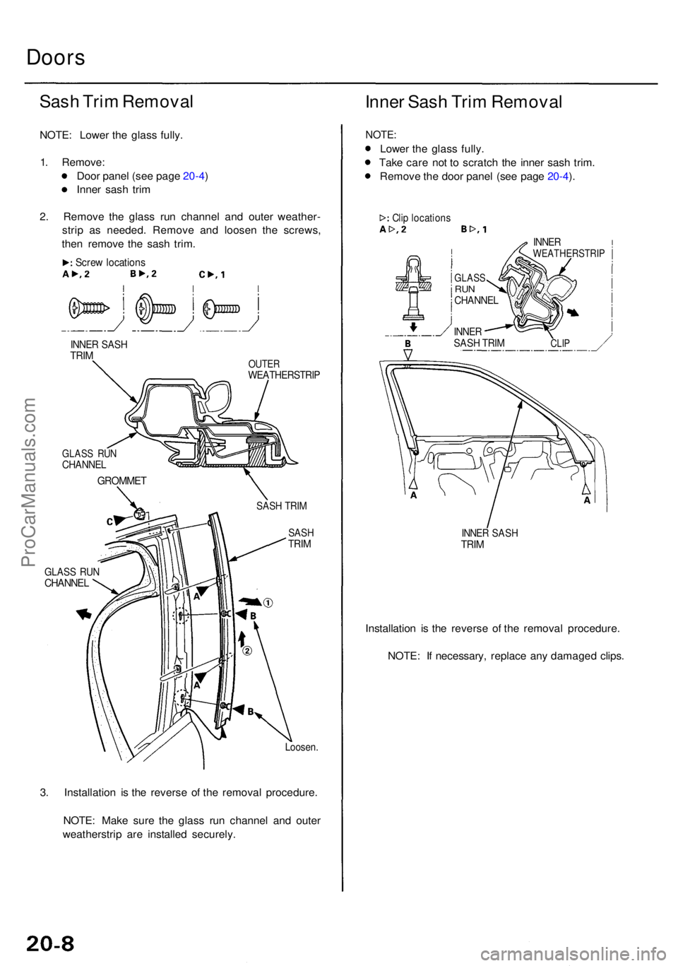
2 . Remov e th e glas s ru n channe l an d oute r weather -
stri p a s needed . Remov e an d loose n th e screws ,
the n remov e th e sas h trim .
Screw location s
INNER SAS HTRIMOUTE RWEATHERSTRI P
GLASS RU NCHANNE L
SASH TRI M
SAS HTRIM
GLAS S RU NCHANNE L
Loosen.
3. Installatio n i s th e revers e o f th e remova l procedure .
NOTE : Mak e sur e th e glas s ru n channe l an d oute r
weatherstri p ar e installe d securely .
Inner Sas h Tri m Remova l
NOTE:
Lower th e glas s fully .
Tak e car e no t t o scratc h th e inne r sas h trim .
Remov e th e doo r pane l (se e pag e 20-4 ).
Cli p location s
INNER SAS HTRIM
Installatio n i s th e revers e o f th e remova l procedure .
NOTE : I f necessary , replac e an y damage d clips .
GROMME T
CLIP
INNE RWEATHERSTRI P
GLASSRUNCHANNE L
INNERSASH TRI M
ProCarManuals.com
Page 1318 of 1954
Rear Doo r Inde x
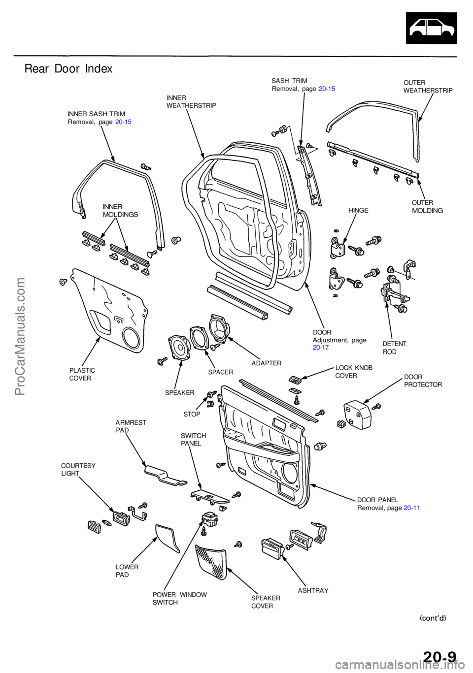
INNER SAS H TRI MRemoval , pag e 20-1 5 SAS
H TRI M
Removal , pag e 20-1 5 OUTE
R
WEATHERSTRI P
INNERWEATHERSTRI P
OUTER
MOLDIN G
COURTES Y
LIGH T DOO
R
PROTECTO R
DOO R PANE L
Removal , pag e 20-1 1
LOWE RPAD
POWE R WINDO WSWITCH
ASHTRA YSPEAKERCOVER
ARMRES TPADSWITC HPANEL
STO
P
SPEAKE R
DOORAdjustment , pag e20-17
ADAPTE R
DETENTROD
LOC K KNO BCOVE RSPACE RPLASTI CCOVER
INNERMOLDING SHINGE
ProCarManuals.com
Page 1319 of 1954
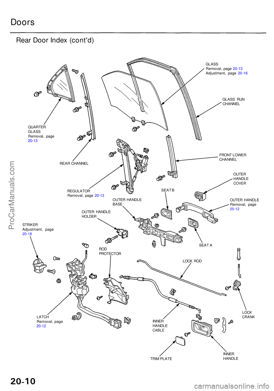
Doors
Rear Doo r Inde x (cont'd )
QUARTE RGLASSRemoval , pag e20-13
STRIKE RAdjustment , pag e20-18
GLAS SRemoval , pag e 20-1 3
Adjustment , pag e 20-1 6
GLAS S RU N
CHANNE L
LATCHRemoval , pag e20-12
FRON T LOWE R
CHANNE L
OUTERHANDL ECOVER
OUTER HANDL E
Removal , pag e
20-12
LOCKCRAN K
TRIM PLAT E INNE
R
HANDL E
REA
R CHANNE L
REGULATO RRemoval, pag e 20-1 3
OUTE R HANDL E
HOLDER
OUTER HANDL EBASE
RODPROTECTO R
INNER
HANDL E
CABLE
LOCK RO D
SEA
T A
SEA
T B
ProCarManuals.com
Page 1320 of 1954
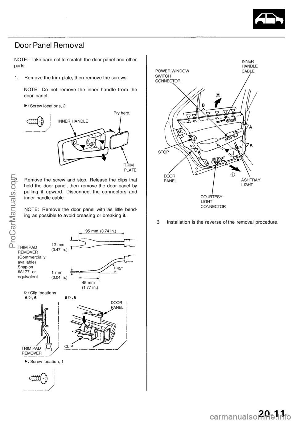
Door Panel Removal
NOTE: Take care not to scratch the door panel and other
parts.
1. Remove the trim plate, then remove the screws.
NOTE: Do not remove the inner handle from the
door panel.
Pry here.
TRIM
PLATE
2. Remove the screw and stop. Release the clips that
hold the door panel, then remove the door panel by
pulling it upward. Disconnect the connectors and
inner handle cable.
NOTE: Remove the door panel with as little bend-
ing as possible to avoid creasing or breaking it.
95 mm
(3.74 in.)
TRIM PAD
REMOVER
(Commercially
available)
Snap-on
#A177, or
equivalent
12 mm
(0.47 in.)
1 mm
(0.04 in.)
45°
45 mm
(1.77 in.)
Clip locations
DOOR
PANEL
CLIP
POWER WINDOW
SWITCH
CONNECTOR
INNER
HANDLE
CABLE
STOP
DOOR
PANEL
ASHTRAY
LIGHT
COURTESY
LIGHT
CONNECTOR
3. Installation is the reverse of the removal procedure.
1
Screw locations, 2
INNER HANDLE
TRIM PAD
REMOVER
Screw location, 1ProCarManuals.com