ACURA RL KA9 1996 Service Repair Manual
Manufacturer: ACURA, Model Year: 1996, Model line: RL KA9, Model: ACURA RL KA9 1996Pages: 1954, PDF Size: 61.44 MB
Page 1351 of 1954
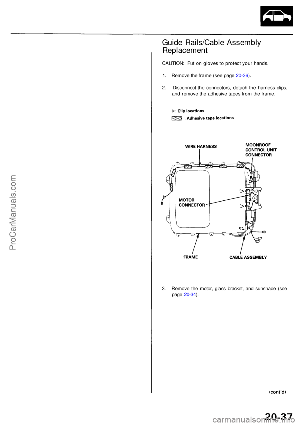
Guide Rails/Cabl e Assembl y
Replacemen t
CAUTION: Pu t o n glove s to protec t you r hands .
1 . Remov e th e fram e (se e pag e 20-36 ).
2 . Disconnec t th e connectors , detac h th e harnes s clips ,
an d remov e th e adhesiv e tape s fro m th e frame .
3 . Remov e th e motor , glas s bracket , an d sunshad e (se e
pag e 20-34 ).
ProCarManuals.com
Page 1352 of 1954
Moonroof
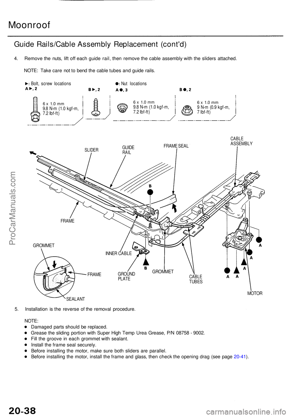
Guide Rails/Cabl e Assembl y Replacemen t (cont'd )
4. Remov e th e nuts , lif t of f eac h guid e rail , the n remov e th e cabl e assembly with th e slider s attached .
NOTE : Tak e car e no t t o ben d th e cabl e tube s an d guid e rails .
Bolt, scre w location s
6 x 1. 0 m m9.8 N- m (1. 0 kgf-m ,
7. 2 Ibf-ft ) Nu
t location s
6 x 1. 0 m m9.8 N- m (1. 0 kgf-m ,
7. 2 Ibf-ft )6 x 1. 0 m m9 N- m (0. 9 kgf-m ,
7 Ibf-ft )
SLIDE RGUIDERAIL
FRAM E SEA L
FRAM E
GROMME T
FRAME GROUN
DPLATECABL ETUBES
CABL EASSEMBL Y
MOTOR
SEALAN T
5. Installatio n i s th e revers e o f th e remova l procedure .
NOTE:
Damage d part s shoul d b e replaced .
Greas e th e slidin g portio n wit h Supe r Hig h Tem p Ure a Grease , P/ N 0875 8 - 9002 .
Fil l th e groov e i n eac h gromme t wit h sealant .
Instal l th e fram e sea l securely .
Befor e installin g th e motor , mak e sur e bot h slider s ar e parallel .
Befor e installin g th e motor , instal l th e fram e an d glass , the n chec k th e openin g dra g (se e pag e 20-41 ).
INNE R CABL E
GROMME T
ProCarManuals.com
Page 1353 of 1954
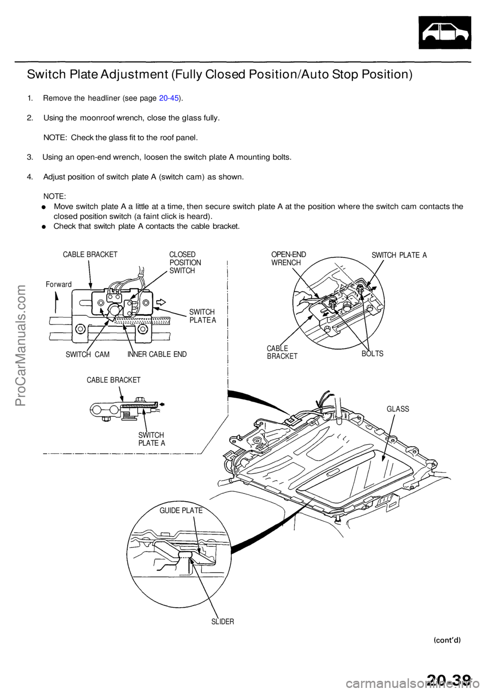
Switch Plat e Adjustmen t (Full y Close d Position/Aut o Sto p Position )
1. Remov e th e headline r (se e pag e 20-45 ).
2 . Usin g th e moonroo f wrench , close the glas s fully .
NOTE : Chec k th e glas s fi t t o th e roo f panel .
3 . Usin g a n open-en d wrench , loose n th e switc h plat e A mountin g bolts .
4 . Adjus t positio n o f switc h plat e A (switc h cam ) a s shown .
NOTE:
Move switc h plat e A a little a t a time , the n secur e switc h plat e A at th e positio n wher e th e switc h ca m contact s th e
close d positio n switc h ( a fain t clic k is heard) .
Chec k tha t switc h plat e A contact s th e cabl e bracket .
CABLE BRACKE T CLOSEDPOSITIO NSWITCH
OPEN-EN DWRENCH SWITC
H PLAT E A
Forwar d
SLIDER
SWITC H
PLAT E A
INNE R CABL E EN D
SWITC H CA M
CABL E BRACKE T
SWITCH
PLAT E A
GUID E PLAT E
CABLEBRACKE TBOLTS
GLAS S
ProCarManuals.com
Page 1354 of 1954
Moonroof
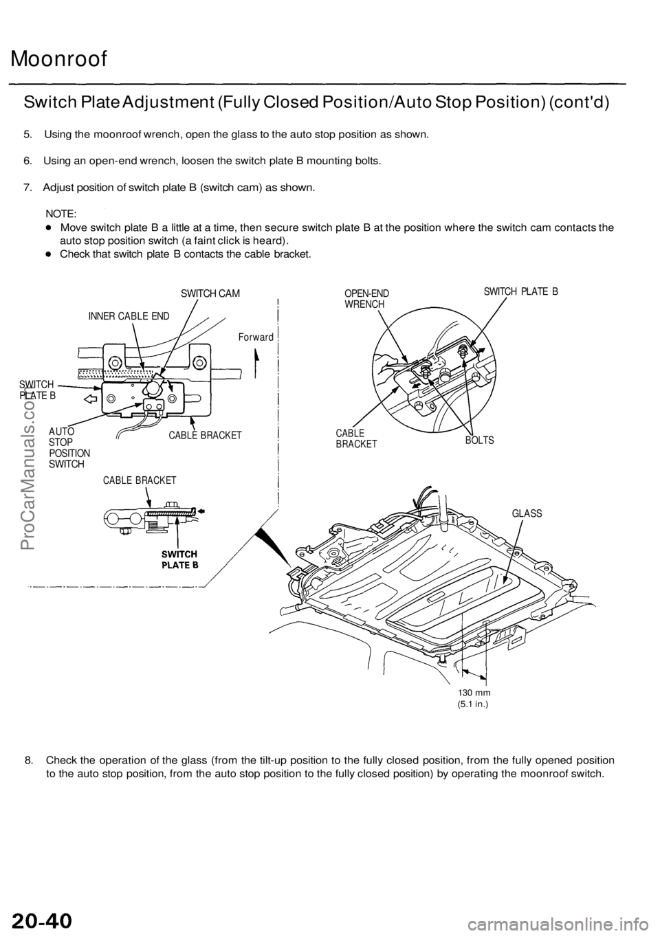
Switch Plate Adjustment (Fully Closed Position/Auto Stop Position) (cont'd)
5. Using the moonroof wrench, open the glass to the auto stop position as shown.
6. Using an open-end wrench, loosen the switch plate B mounting bolts.
7. Adjust position of switch plate B (switch cam) as shown.
NOTE:
Move switch plate B a little at a time, then secure switch plate B at the position where the switch cam contacts the
auto stop position switch (a faint click is heard).
Check that switch plate B contacts the cable bracket.
SWITCH CAM
INNER CABLE END
SWITCH
PLATE B
AUTO
STOP
POSITION
SWITCH
OPEN-END
WRENCH
SWITCH PLATE B
Forward
CABLE BRACKET
CABLE
BRACKET
BOLTS
GLASS
130 mm
(5.1 in.)
8. Check the operation of the glass (from the tilt-up position to the fully closed position, from the fully opened position
to the auto stop position, from the auto stop position to the fully closed position) by operating the moonroof switch.
CABLE BRACKETProCarManuals.com
Page 1355 of 1954
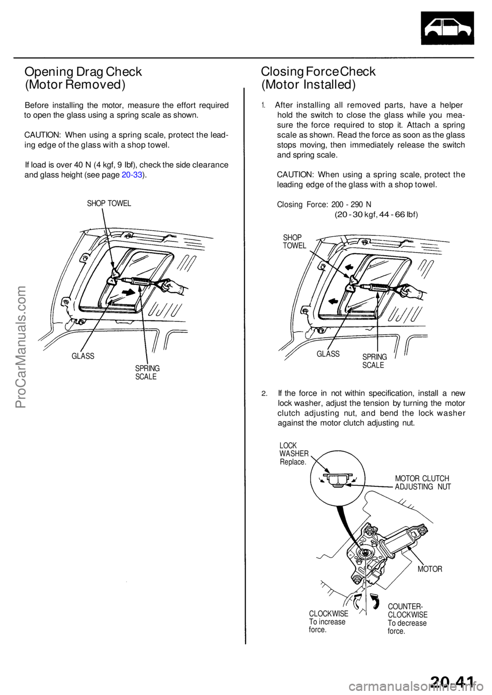
Opening Dra g Chec k
(Moto r Removed )
Before installin g th e motor , measur e th e effor t require d
t o ope n th e glas s usin g a sprin g scal e a s shown .
CAUTION : Whe n usin g a sprin g scale , protec t th e lead -
in g edg e o f th e glas s wit h a sho p towel .
I f loa d is ove r 4 0 N (4 kgf , 9 Ibf) , chec k th e sid e clearanc e
an d glas s heigh t (se e pag e 20-33 ).
SHO P TOWE L
GLASS
SPRIN GSCALE
Closin g Forc e Chec k
(Moto r Installed )
1. Afte r installin g al l remove d parts , hav e a helpe r
hol d th e switc h t o clos e th e glas s whil e yo u mea -
sur e th e forc e require d t o sto p it . Attac h a sprin g
scal e a s shown . Rea d th e forc e a s soo n a s th e glas s
stop s moving , the n immediatel y releas e th e switc h
an d sprin g scale .
CAUTION : Whe n usin g a sprin g scale , protec t th e
leadin g edg e o f th e glas s wit h a sho p towel .
Closin g Force : 20 0 - 29 0 N
(2 0 - 3 0 kgf , 44 - 6 6 Ibf )
SHO PTOWE L
2.
SPRIN GSCALE
If th e forc e i n no t withi n specification , instal l a ne w
loc k washer , adjus t th e tensio n b y turnin g th e moto r
clutc h adjustin g nut , an d ben d th e loc k washe r
agains t th e moto r clutc h adjustin g nut .
LOC KWASHE RReplace .
MOTOR CLUTC H
ADJUSTIN G NU T
MOTO R
CLOCKWIS ETo increas e
force . COUNTER
-CLOCKWIS ETo decreas e
force .
GLAS
S
ProCarManuals.com
Page 1356 of 1954
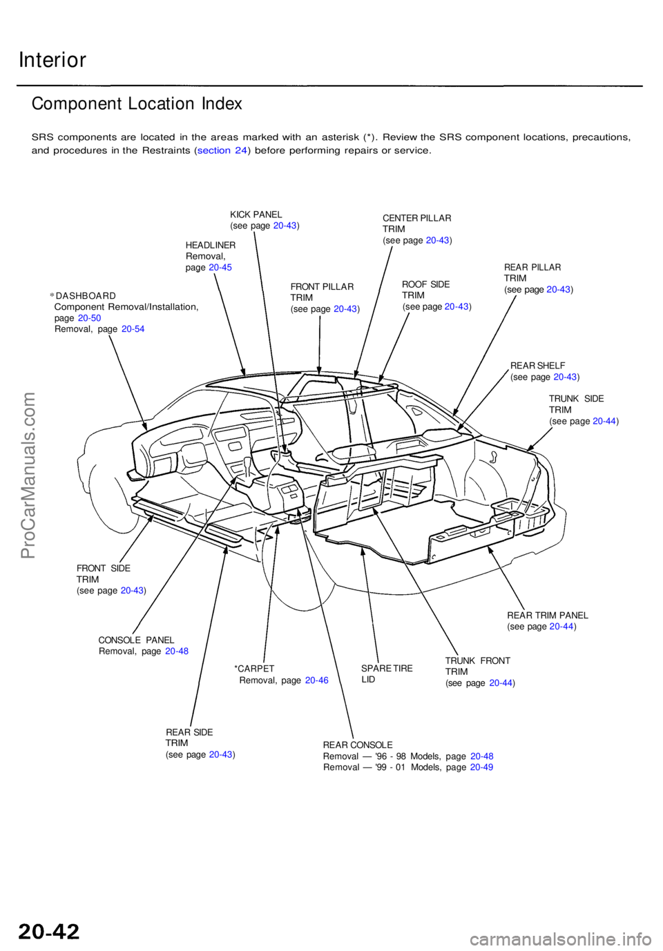
Interior
Componen t Locatio n Inde x
SRS component s ar e locate d i n th e area s marke d wit h a n asteris k (*) . Revie w th e SR S componen t locations , precautions ,
an d procedure s i n th e Restraint s ( sectio n 24 ) befor e performin g repair s o r service .
*DASHBOAR DComponent Removal/Installation ,page 20-5 0
Removal , pag e 20-5 4
REAR SHEL F
(se e pag e 20-43 )
TRUN K SID E
TRIM(see pag e 20-44 )
FRON T SID E
TRIM(see pag e 20-43 )
CONSOL E PANE L
Removal , pag e 20-4 8 REA
R TRI M PANE L
(se e pag e 20-44 )
REA R SID E
TRIM(see pag e 20-43 ) TRUN
K FRON T
TRIM(see pag e 20-44 )
REA R CONSOL E
Remova l — '96 - 9 8 Models , pag e 20-4 8
Remova l — '99 - 0 1 Models , pag e 20-4 9
*CARPE TRemoval , pag e 20-4 6 SPAR
E TIR ELID
REA R PILLA RTRIM(see pag e 20-43 )ROOF SID ETRIM(see pag e 20-43 )
CENTE
R PILLA R
TRIM(see pag e 20-43 )
FRON T PILLA R
TRIM(see pag e 20-43 )
KIC
K PANE L
(se e pag e 20-43 )
HEADLINE R
Removal,page 20-4 5
ProCarManuals.com
Page 1357 of 1954
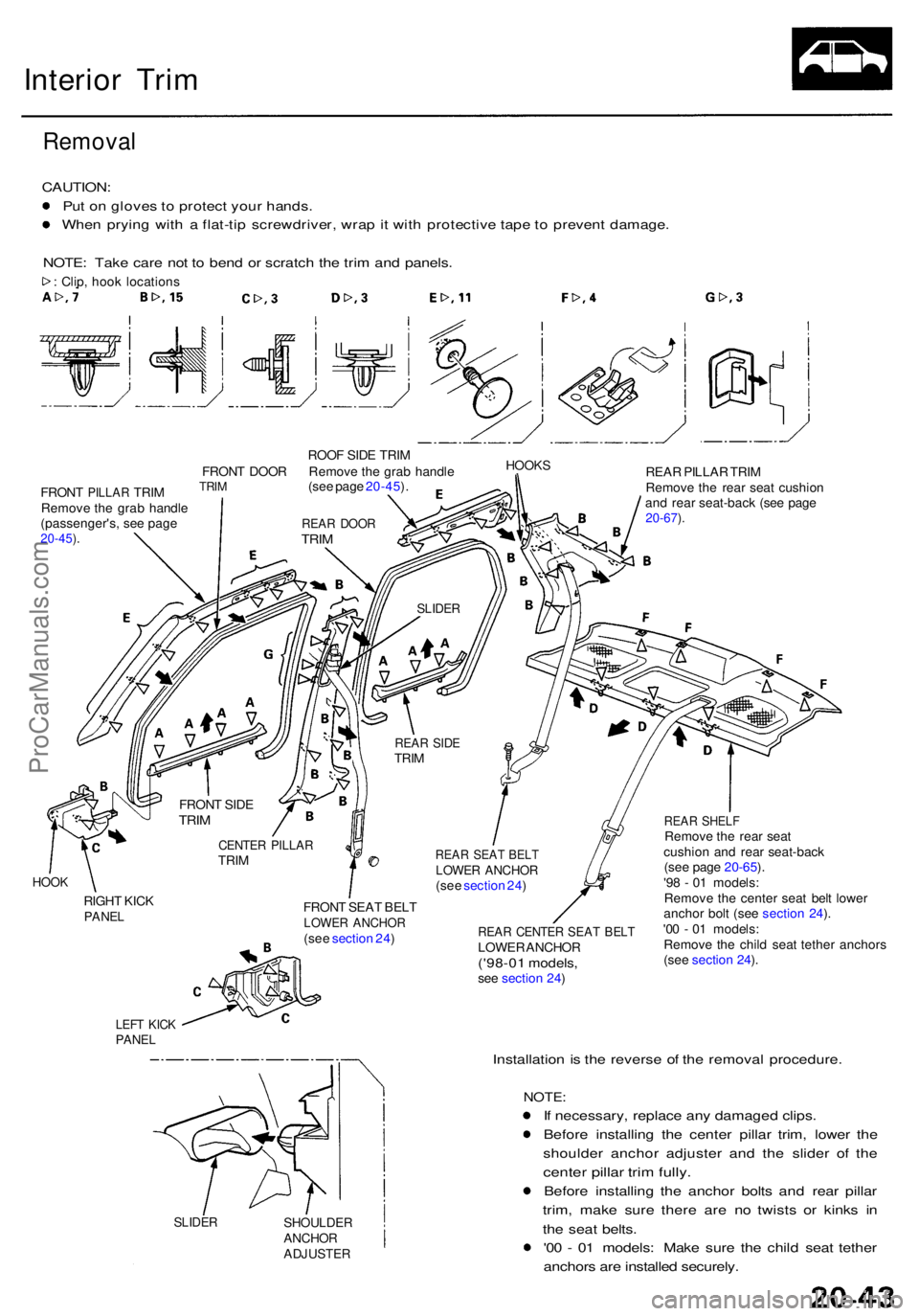
Interior Tri m
Remova l
CAUTION :
Pu t o n glove s to protec t you r hands .
Whe n pryin g wit h a flat-ti p screwdriver , wra p it wit h protectiv e tap e t o preven t damage .
NOTE : Tak e car e no t t o ben d o r scratc h th e tri m an d panels .
: Clip , hoo k location s
ROOF SID E TRI M
FRON T DOO R Remov e th e gra b handl e
HOOK S
FRONT PILLA R TRIM TRIM
Remov e th e gra b handl e
(passenger's , se e pag e
20-45 ).
(se e pag e 20-45 ). REA
R PILLA R TRI M
Remov e th e rea r sea t cushio n
an d rea r seat-bac k (se e pag e
20-67 ).
HOO K
RIGH T KIC KPANE L
LEFT KIC KPANE L
FRON T SEA T BEL TLOWE R ANCHO R(see sectio n 24 ) REA R CENTE R SEA T BEL TLOWE R ANCHO R('98-01 models ,see sectio n 24 )
REA R SHEL FRemov e th e rea r sea t
cushio n an d rea r seat-bac k
(se e pag e 20-65 ).
'9 8 - 0 1 models :
Remov e th e cente r sea t bel t lowe r
ancho r bol t (se e sectio n 24 ).
'0 0 - 0 1 models :
Remov e th e chil d sea t tethe r anchor s
(se e sectio n 24 ).
SLIDE RSHOULDE RANCHORADJUSTE R
Installation i s th e revers e o f th e remova l procedure .
NOTE:
If necessary , replac e an y damage d clips .
Befor e installin g th e cente r pilla r trim , lowe r th e
shoulde r ancho r adjuste r an d th e slide r o f th e
cente r pilla r tri m fully .
Befor e installin g th e ancho r bolt s an d rea r pilla r
trim , mak e sur e ther e ar e n o twist s o r kink s i n
th e sea t belts .
'0 0 - 0 1 models : Mak e sur e th e chil d sea t tethe r
anchor s ar e installe d securely .
REAR SEA T BEL TLOWE R ANCHO R(see sectio n 24 )
CENTE R PILLA RTRIM
FRON
T SID E
TRIM
REA R SID ETRIM
SLIDE R
REAR DOO RTRIM
ProCarManuals.com
Page 1358 of 1954
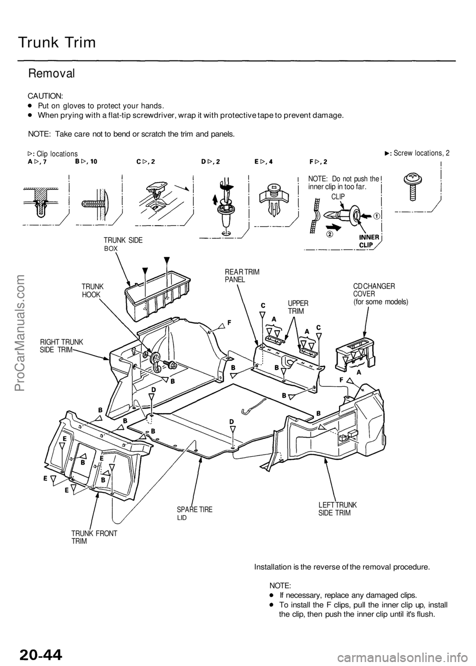
Trunk Tri m
Remova l
CAUTION :
Put o n glove s t o protec t you r hands .
When pryin g wit h a flat-ti p screwdriver , wra p it wit h protectiv e tap e to preven t damage .
NOTE : Tak e car e no t t o ben d o r scratc h th e tri m an d panels .
Clip location s Scre
w locations , 2
TRUN K SID E
BOX
TRUN KHOOK
RIGH T TRUN K
SID E TRI M NOTE
: D o no t pus h th e
inne r cli p in to o far .
CLI P
REA R TRI M
PANE L
CD CHANGE R
COVER(for som e models )
LEFT TRUN K
SID E TRI M
TRUN K FRON T
TRI M
Installatio n is th e revers e o f th e remova l procedure .
NOTE:
If necessary , replac e an y damage d clips .
T o instal l th e F clips , pul l th e inne r cli p up , instal l
th e clip , the n pus h th e inne r cli p unti l it' s flush .
SPAR E TIR ELID
UPPE RTRIM
ProCarManuals.com
Page 1359 of 1954
Headliner
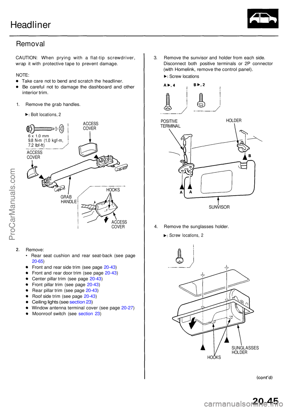
Removal
CAUTION : Whe n pryin g wit h a flat-ti p screwdriver ,
wra p i t wit h protectiv e tap e t o preven t damage .
NOTE:
Take car e no t t o ben d an d scratc h th e headliner .
Be carefu l no t t o damag e th e dashboar d an d othe r
interio r trim .
1. Remov e th e gra b handles .
Bolt locations , 2
ACCES S
COVE R
6 x 1. 0 m m9.8 N- m (1. 0 kgf-m ,7.2 Ibf-ft )
ACCES SCOVER
Remove :
• Rea r sea t cushio n an d rea r seat-bac k (se e pag e
20-65 )
Front an d rea r sid e tri m (se e pag e 20-43 )
Fron t an d rea r doo r tri m (se e pag e 20-43 )
Cente r pilla r tri m (se e pag e 20-43 )
Fron t pilla r tri m (se e pag e 20-43 )
Rea r pilla r tri m (se e pag e 20-43 )
Roo f sid e tri m (se e pag e 20-43 )
Ceiling light s (se e sectio n 23 )
Windo w antenn a termina l cove r (se e pag e 20-27 )
Moonroo f switc h (se e sectio n 23 ) 3
. Remov e th e sunviso r an d holde r fro m eac h side .
Disconnec t bot h positiv e terminal s o r 2 P connecto r
(with Homelink , remov e th e contro l panel) .
Screw location s
POSITIV ETERMINA L
SUNVISO R
4. Remov e th e sunglasse s holder .
Screw locations , 2
SUNGLASSE SHOLDER
HOOK SHOLDE
R
GRA B
HANDL E
HOOKS
ACCES
S
COVE R
ProCarManuals.com
Page 1360 of 1954
Headliner
Removal (cont'd )
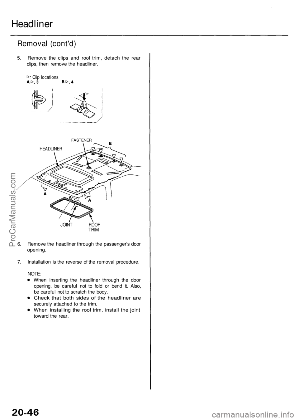
5. Remov e th e clip s an d roo f trim , detac h th e rea r
clips , the n remov e th e headliner .
Clip location s
FASTENE R
HEADLINE R
JOINTROO FTRIM
6. Remov e th e headline r throug h th e passenger' s doo r
opening .
7. Installatio n i s th e revers e o f th e remova l procedure .
NOTE:
When insertin g th e headline r throug h th e doo r
opening , b e carefu l no t t o fol d o r ben d it . Also ,
b e carefu l no t t o scratc h th e body .
Chec k tha t bot h side s o f th e headline r ar e
securel y attache d t o th e trim .
Whe n installin g th e roo f trim , instal l th e join t
towar d th e rear .
ProCarManuals.com