ACURA RL KA9 1996 Service Repair Manual
Manufacturer: ACURA, Model Year: 1996, Model line: RL KA9, Model: ACURA RL KA9 1996Pages: 1954, PDF Size: 61.44 MB
Page 611 of 1954
Idle Contro l Syste m
System Descriptio n
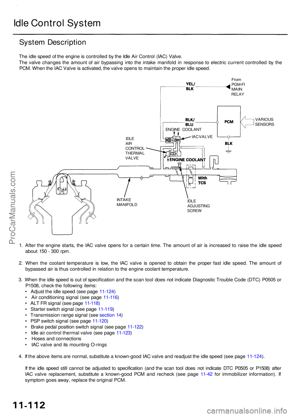
The idl e spee d o f th e engin e is controlle d b y th e Idl e Ai r Contro l (IAC ) Valve .
Th e valv e change s th e amoun t o f ai r bypassin g int o th e intak e manifol d i n respons e t o electri c curren t controlle d b y th e
PCM . Whe n th e IA C Valv e is activated , th e valv e open s to maintai n th e prope r idl e speed .
VARIOU S
SENSOR S
INTAK E
MANIFOL D
IDLEADJUSTIN GSCREW
1. Afte r th e engin e starts , th e IA C valv e open s fo r a certai n time . Th e amoun t o f ai r i s increase d t o rais e th e idl e spee d
abou t 15 0 - 30 0 rpm .
2 . Whe n th e coolan t temperatur e i s low , th e IA C valv e i s opene d t o obtai n th e prope r fas t idl e speed . Th e amoun t o f
bypasse d ai r i s thu s controlle d in relatio n to th e engin e coolan t temperature .
3 . Whe n th e idl e spee d is ou t o f specificatio n an d th e sca n too l doe s no t indicat e Diagnosti c Troubl e Cod e (DTC ) P050 5 o r
P1508 , chec k th e followin g items :
• Adjus t th e idl e spee d (se e pag e 11-124 )
• Ai r conditionin g signa l (se e pag e 11-116 )
• AL T F R signa l (se e pag e 11-118 )
• Starte r switc h signa l (se e pag e 11-119 )
• Transmissio n rang e signa l (se e sectio n 14 )
• PS P switc h signa l (se e pag e 11-120 )
• Brak e peda l positio n switc h signa l (se e pag e 11-122 )
• Idl e ai r contro l therma l valv e (se e pag e 11-123 )
• Hose s an d connection s
• IA C valv e an d it s mountin g O-ring s
4 . I f th e abov e item s ar e normal , substitut e a known-goo d IA C valv e an d readjus t th e idl e spee d (se e pag e 11-124 ).
I f th e idl e spee d stil l canno t b e adjuste d t o specificatio n (an d th e sca n too l doe s no t indicat e DT C P050 5 o r P1508 ) afte r
IA C valv e replacement , substitut e a known-goo d PC M an d rechec k (se e pag e 11-42 fo r immobilize r information) . I f
sympto m goe s away , replac e th e origina l PCM .
IDLEAIRCONTRO LTHERMA LVALVE
IAC VALV E
FromPGM-F IMAINRELA Y
ENGIN E COOLAN T
ProCarManuals.com
Page 612 of 1954
Idle Contro l Syste m
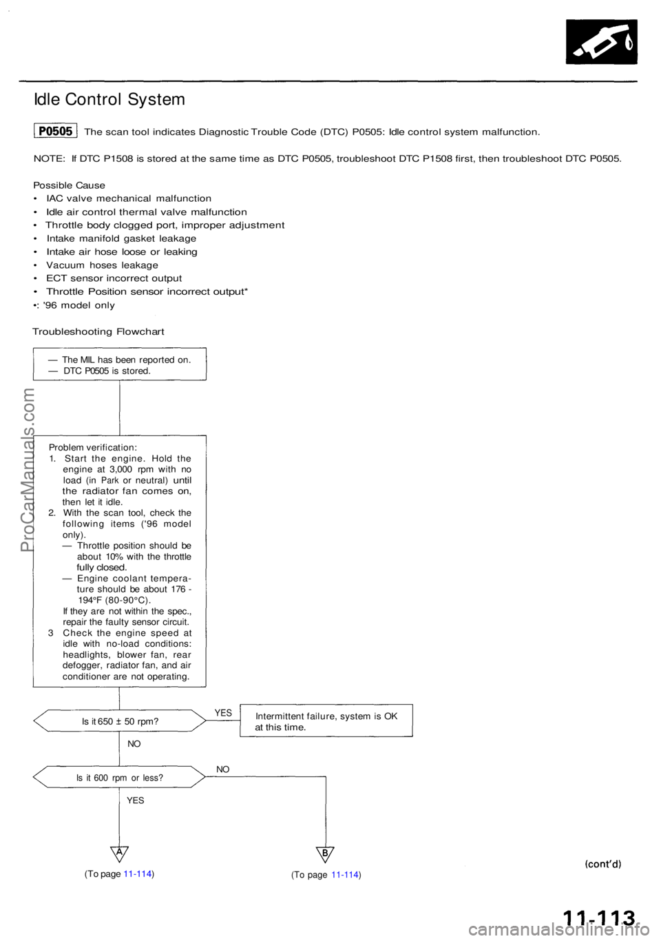
NOTE: I f DT C P150 8 is store d a t th e sam e tim e a s DT C P0505 , troubleshoo t DT C P150 8 first , the n troubleshoo t DT C P0505 .
Possibl e Caus e
• IA C valv e mechanica l malfunctio n
• Idl e ai r contro l therma l valv e malfunctio n
• Throttl e bod y clogge d port , imprope r adjustmen t
• Intak e manifol d gaske t leakag e
• Intak e ai r hos e loos e o r leakin g
• Vacuu m hose s leakag e
• EC T senso r incorrec t outpu t
• Throttl e Positio n senso r incorrec t output *
•: '9 6 mode l onl y
— Th e MI L ha s bee n reporte d on .
— DT C P050 5 is stored .
Proble m verification :
1 . Star t th e engine . Hol d th e
engin e a t 3,00 0 rp m wit h n o
loa d
(in Par k or neutral ) untilthe radiato r fa n come s on ,then le t i t idle .
2 . Wit h th e sca n tool , chec k th e
followin g item s ('9 6 mode l
only) .
— Throttl e positio n shoul d b e
abou t 10 % wit h th e throttl e
fully closed .— Engin e coolan t tempera -
tur e shoul d b e abou t 17 6 -
194° F (80-90°C) .
I f the y ar e no t withi n th e spec. ,
repai r th e fault y senso r circuit .
3 Chec k th e engin e spee d a t
idl e wit h no-loa d conditions :
headlights , blowe r fan , rea r
defogger , radiato r fan , an d ai r
conditione r ar e no t operating .
Is i t 65 0 5 0 rpm ?
NO
Is i t 60 0 rp m o r less ?
YES
Intermitten t failure , syste m is O Kat thi s time .
NO
(T o pag e 11-114 ) (T o pag e 11-114 )
YES
The sca n too l indicate s Diagnosti c Troubl e Cod e (DTC ) P0505 : Idl e contro l syste m malfunction .
Troubleshootin g Flowchar t
ProCarManuals.com
Page 613 of 1954
Idle Contro l Syste m
Idle Contro l Syste m (cont'd )
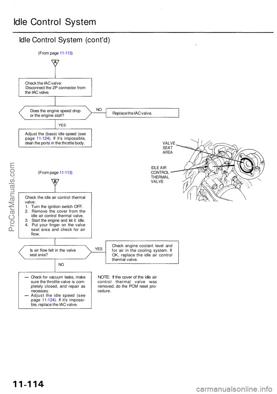
(From pag e 11-113 )
Chec k th e IA C valve :
Disconnec t th e 2 P connecto r fro m
the IA C valve .
Does th e engin e spee d dro p
o r th e engin e stall ? Replac
e th e IA C valve .
YES
Adjus t th e (base ) idl e spee d (se e
pag e 11-124 ). I f it' s impossible ,
dea n th e port s in th e throttl e body .
(Fro m pag e 11-113 )
IDLE AI RCONTRO LTHERMA LVALVE
Check th e idl e ai r contro l therma l
valve :
1 . Tur n th e ignitio n switc h OFF .
2 . Remov e th e cove r fro m th e
idl e ai r contro l therma l valve .
3 . Star t th e engin e an d le t i t idle .
4 . Pu t you r finge r o n th e valv e
sea t are a an d chec k fo r ai r
flow .
Is ai r flo w fel t i n th e valv eseat area ?
NO
Chec k engin e coolan t leve l an d
fo r ai r i n th e coolin g system . I f
OK , replac e th e idl e ai r contro l
therma l valve .
Chec k fo r vacuu m leaks , mak e
sur e th e throttl e valv e is com -
pletel y closed , an d repai r a s
necessary .Adjust th e idl e spee d (se e
pag e 11-124 ). I f it' s impossi -
ble , replac e th e IA C valve .
NOTE: I f th e cove r o f th e idl e ai rcontro l therma l valv e wa s
removed , d o th e PC M rese t pro -
cedure .
YES
NO
VALV ESEATARE A
ProCarManuals.com
Page 614 of 1954
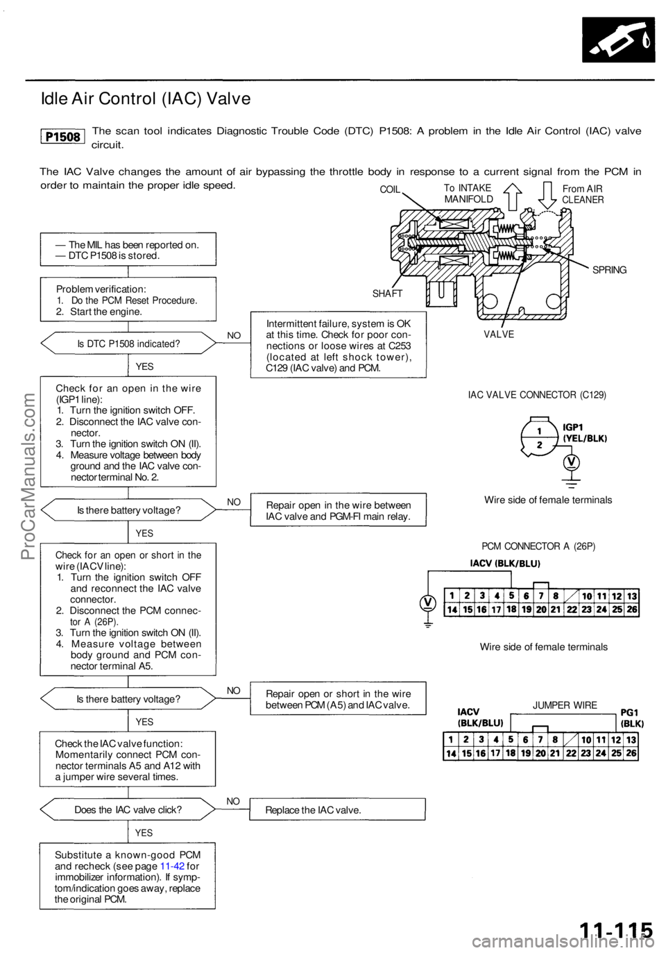
— Th e MI L ha s bee n reporte d on .
— DT C P150 8 is stored .
Proble m verification :
1. D o th e PC M Rese t Procedure .2. Star t th e engine .
Is DT C P150 8 indicated ?
YES
Chec k fo r a n ope n i n the wire
(IGP 1 line) :
1 . Tur n th e ignitio n switc h OFF .
2 . Disconnec t th e IA C valv e con -
nector .
3 . Tur n th e ignitio n switc h O N (II) .
4 . Measur e voltag e betwee n bod y
groun d an d th e IA C valv e con -
necto r termina l No . 2 .
I s ther e batter y voltage ?
I s ther e batter y voltage ?
YES
Chec k th e IA C valv e function :
Momentaril y connec t PC M con -
necto r terminal s A 5 an d A1 2 wit h
a jumpe r wire severa l times .
Doe s th e IA C valv e click ?
YES
Substitut e a known-goo d PC M
an d rechec k (se e pag e 11-42 fo r
immobilize r information) . I f symp -
tom/indicatio n goe s away , replac e
th e origina l PCM .
SHAF T
Intermitten t failure , syste m is O K
a t thi s time . Chec k fo r poo r con -
nection s o r loos e wire s a t C25 3
(locate d a t lef t shoc k tower) ,
C12 9 (IA C valve ) an d PCM .
SPRIN G
IAC VALV E CONNECTO R (C129 )
Repair ope n in th e wir e betwee n
IA C valv e an d PGM-F I mai n relay . Wir
e sid e o f femal e terminal s
PCM CONNECTO R A (26P )
Repai r ope n o r shor t i n th e wir e
betwee n PC M (A5 ) an d IA C valve . Wir
e sid e o f femal e terminal sJUMPER WIR E
Replac e th e IA C valve .NO
NO
Chec k fo r a n ope n o r shor t i n th ewir e (IAC V line) :
1 . Tur n th e ignitio n switc h OF F
an d reconnec t th e IA C valv e
connector .2. Disconnec t th e PC M connec -tor A (26P) .3. Tur n th e ignitio n switc h O N (II) .
4 . Measur e voltag e betwee n
bod y groun d an d PC M con -
necto r termina l A5 .
NO
YE S
VALV E
To INTAK EMANIFOL DFrom AI RCLEANE RCOIL
NO
Idl e Ai r Contro l (IAC ) Valv e
The sca n too l indicate s Diagnosti c Troubl e Cod e (DTC ) P1508 : A proble m in th e Idl e Ai r Contro l (IAC ) valv e
circuit .
The IA C Valv e change s th e amoun t o f ai r bypassin g th e throttl e bod y i n respons e t o a curren t signa l fro m th e PC M in
orde r t o maintai n th e prope r idl e speed .
ProCarManuals.com
Page 615 of 1954
Idle Contro l Syste m
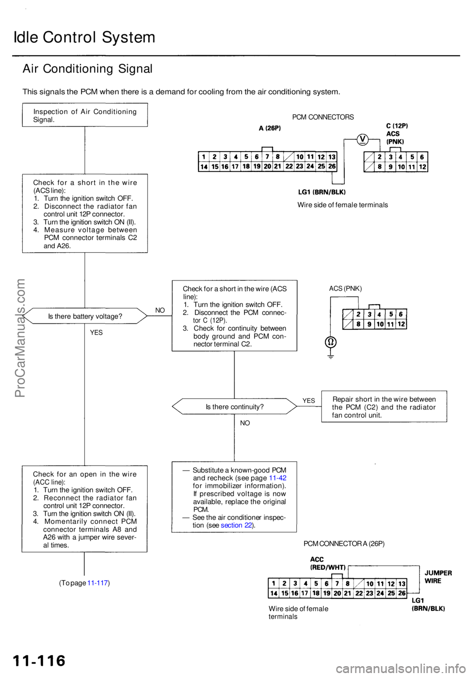
Air Conditionin g Signa l
This signal s th e PC M whe n ther e is a deman d fo r coolin g fro m th e ai r conditionin g system .
Inspectio n o f Ai r Conditionin g
Signal .PCM CONNECTOR S
Check fo r a shor t i n th e wir e
(AC S line) :
1 . Tur n th e ignitio n switc h OFF .
2 . Disconnec t th e radiato r fa n
contro l uni t 12 P connector .
3 . Tur n th e ignitio n switc h O N (II) .
4 . Measur e voltag e betwee n
PC M connecto r terminal s C 2
an d A26 .
Wire sid e o f femal e terminal s
I s ther e batter y voltage ?
NO
YE S
Chec k fo r a n ope n i n th e wir e(ACC line) :1. Tur n th e ignitio n switc h OFF .
2 . Reconnec t th e radiato r fa n
contro l uni t 12 P connector .
3 . Tur n th e ignitio n switc h O N (II) .
4 . Momentaril y connec t PC M
connecto r terminal s A 8 an d
A2 6 wit h a jumpe r wir e sever -
a l times .
ACS (PNK )
YESRepai r shor t i n th e wir e betwee n
th e PC M (C2 ) an d th e radiato r
fa n contro l unit .
PC M CONNECTO R A (26P )
(T o pag e 11-117 )
Wire sid e o f femal e
terminal s
— Substitut e a known-goo d PC M
an d rechec k (se e pag e 11-42
fo r immobilize r information) .
I f prescribe d voltag e i s no w
available , replac e th e origina l
PCM.— Se e th e ai r conditione r inspec -
tio n (se e sectio n 22 ).
I
s ther e continuity ?
NO
Chec k fo r a shor t i n th e wir e (AC Sline):1. Tur n th e ignitio n switc h OFF .
2 . Disconnec t th e PC M connec -
tor C (12P) .3. Chec k fo r continuit y betwee n
bod y groun d an d PC M con -
necto r termina l C2 .
ProCarManuals.com
Page 616 of 1954
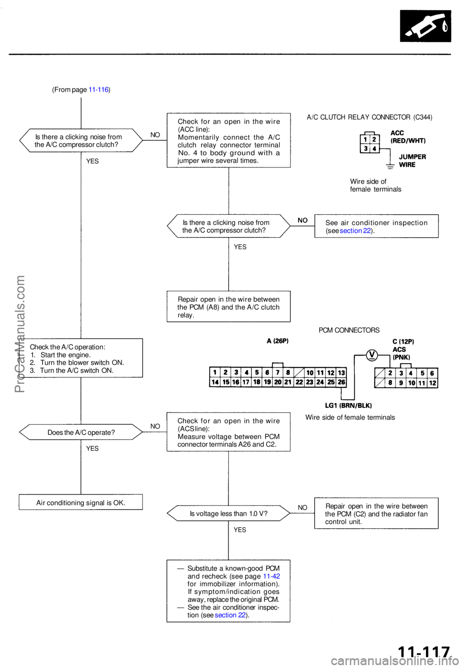
(From pag e 11-116 )
I s ther e a clickin g nois e fro m
th e A/ C compresso r clutch ?
NO
YE S
Chec k fo r a n ope n i n th e wir e(ACC line) :Momentaril y connec t th e A/ C
clutc h rela y connecto r termina l
No. 4 to bod y groun d wit h ajumpe r wir e severa l times .
A/C CLUTC H RELA Y CONNECTO R (C344 )
Wire sid e o f
femal e terminal s
I s ther e a clickin g nois e fro m
th e A/ C compresso r clutch ? Se
e ai r conditione r inspectio n
(se e sectio n 22 ).
YE S
Repai r ope n in th e wir e betwee n
th e PC M (A8 ) an d th e A/ C clutc h
relay.
PCM CONNECTOR S
Check th e A/ C operation :
1 . Star t th e engine .
2 . Tur n th e blowe r switc h ON .
3 . Tur n th e A/ C switc h ON .
Doe s th e A/ C operate ?
YES
Chec k fo r a n ope n i n th e wir e
(AC S line) :
Measur e voltag e betwee n PC M
connecto r terminal s A2 6 an d C2 .
Ai r conditionin g signa l i s OK . Wir
e sid e o f femal e terminal s
I s voltag e les s tha n 1. 0 V ?
YE S
Repai r ope n in th e wir e betwee n
th e PC M (C2 ) an d th e radiato r fa n
contro l unit .
— Substitut e a known-goo d PC M
an d rechec k (se e pag e 11-42
fo r immobilize r information) .
I f symptom/indicatio n goe s
away , replac e th e origina l PCM .
— Se e th e ai r conditione r inspec -
tio n (se e sectio n 22 ).N O
NO
ProCarManuals.com
Page 617 of 1954
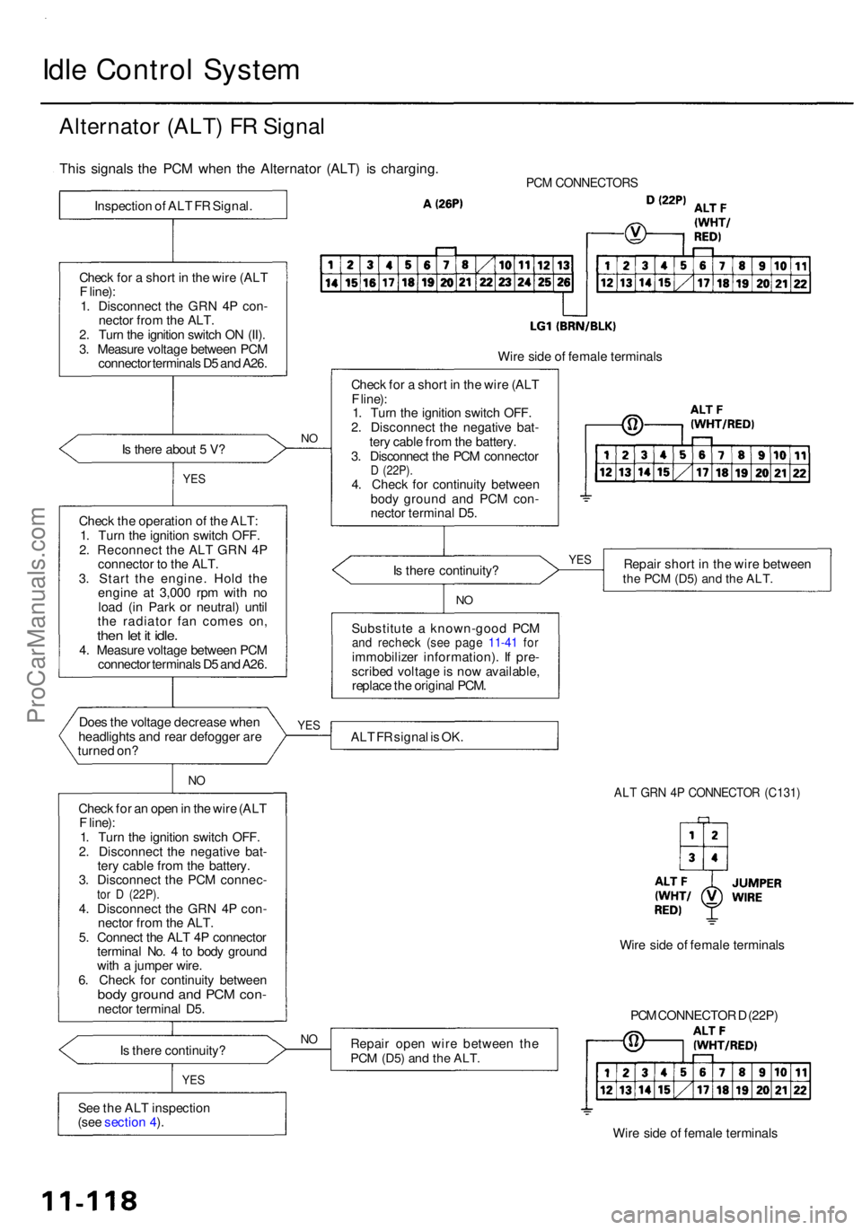
Idle Contro l Syste m
Alternato r (ALT ) F R Signa l
PCM CONNECTOR S
Is ther e abou t 5 V ?
YE S
Chec k th e operatio n o f th e ALT :
1 . Tur n th e ignitio n switc h OFF .
2 . Reconnec t th e AL T GR N 4 P
connecto r t o th e ALT .
3 . Star t th e engine . Hol d th e
engin e a t 3,00 0 rp m wit h n o
loa d (i n Par k o r neutral ) unti l
th e radiato r fa n come s on ,
then le t i t idle .4. Measur e voltag e betwee n PC M
connecto r terminal s D 5 an d A26 .
Doe s th e voltag e decreas e whe n
headlight s an d rea r defogge r ar e
turne d on ?
NO
Chec k fo r a n ope n in th e wir e (AL T
F line) :
1 . Tur n th e ignitio n switc h OFF .
2 . Disconnec t th e negativ e bat -
ter y cabl e fro m th e battery .
3 . Disconnec t th e PC M connec -
tor D (22P) .4. Disconnec t th e GR N 4 P con -
necto r fro m th e ALT .
5 . Connec t th e AL T 4 P connecto r
termina l No . 4 to bod y groun d
wit h a jumpe r wire .
6 . Chec k fo r continuit y betwee n
body groun d an d PC M con -necto r termina l D5 .
I s ther e continuity ?
YES
See th e AL T inspectio n
(see sectio n 4 ).
N O
Wir e sid e o f femal e terminal s
Chec k fo r a shor t i n th e wir e (AL T
F line) :
1 . Tur n th e ignitio n switc h OFF .
2 . Disconnec t th e negativ e bat -
ter y cabl e fro m th e battery .
3 . Disconnec t th e PC M connecto r
D (22P) .4. Chec k fo r continuit y betwee n
bod y groun d an d PC M con -
necto r termina l D5 .
I s ther e continuity ? Repai
r shor t i n th e wir e betwee n
the PC M (D5 ) and th e ALT .
NO
Substitut e a known-goo d PC Mand rechec k (se e pag e 11-4 1 fo rimmobilize r information) . I f pre -
scribe d voltag e is no w available ,
replac e th e origina l PCM .
AL T F R signa l i s OK .
ALT GR N 4 P CONNECTO R (C131 )
Repair ope n wir e betwee n th ePCM (D5 ) and th e ALT .
PCM CONNECTO R D (22P )
Wir e sid e o f femal e terminal s
NO
Wir e sid e o f femal e terminal s
YES YE
S
This signal s th e PC M whe n th e Alternato r (ALT ) i s charging .
Inspection o f AL T F R Signal .
Chec k fo r a shor t i n th e wir e (AL T
F line) :
1 . Disconnec t th e GR N 4 P con -
necto r fro m th e ALT .
2 . Tur n th e ignitio n switc h O N (II) .
3 . Measur e voltag e betwee n PC M
connecto r terminal s D 5 an d A26 .
ProCarManuals.com
Page 618 of 1954
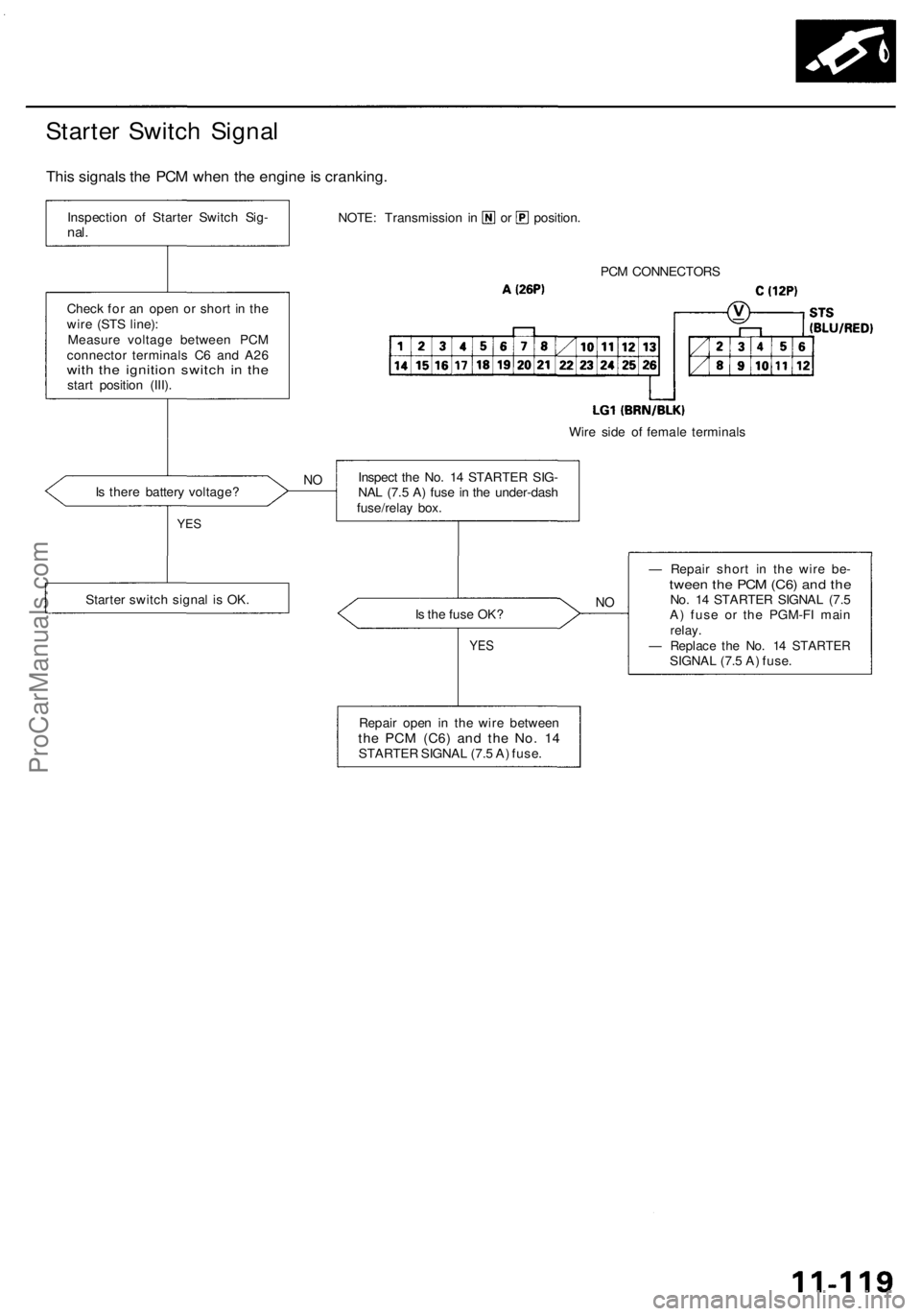
PCM CONNECTOR S
Wir e sid e o f femal e terminal s
I s ther e batter y voltage ?
Is th e fus e OK ?
NO
— Repai r shor t i n th e wir e be -twee n th e PC M (C6 ) an d th eNo . 1 4 STARTE R SIGNA L (7. 5
A ) fus e o r th e PGM-F I mai n
relay .— Replac e th e No . 1 4 STARTE RSIGNAL (7. 5 A ) fuse .
Repai r ope n i n th e wir e betwee n
the PC M (C6 ) and th e No . 1 4STARTE R SIGNA L (7. 5 A ) fuse .
YES
Inspec t th e No . 1 4 STARTE R SIG -
NA L (7. 5 A ) fus e in th e under-das h
fuse/rela y box .NO
YE S
Starte r switc h signa l i s OK .
Chec
k fo r a n ope n o r shor t i n th e
wir e (ST S line) :
Measur e voltag e betwee n PC M
connecto r terminal s C 6 an d A2 6
with th e ignitio n switc h i n th estar t positio n (III) .
NOTE : Transmissio n i n o r position .
Inspectio
n o f Starte r Switc h Sig -nal.
Thi s signal s th e PC M whe n th e engin e is cranking .
Starter Switc h Signa l
ProCarManuals.com
Page 619 of 1954
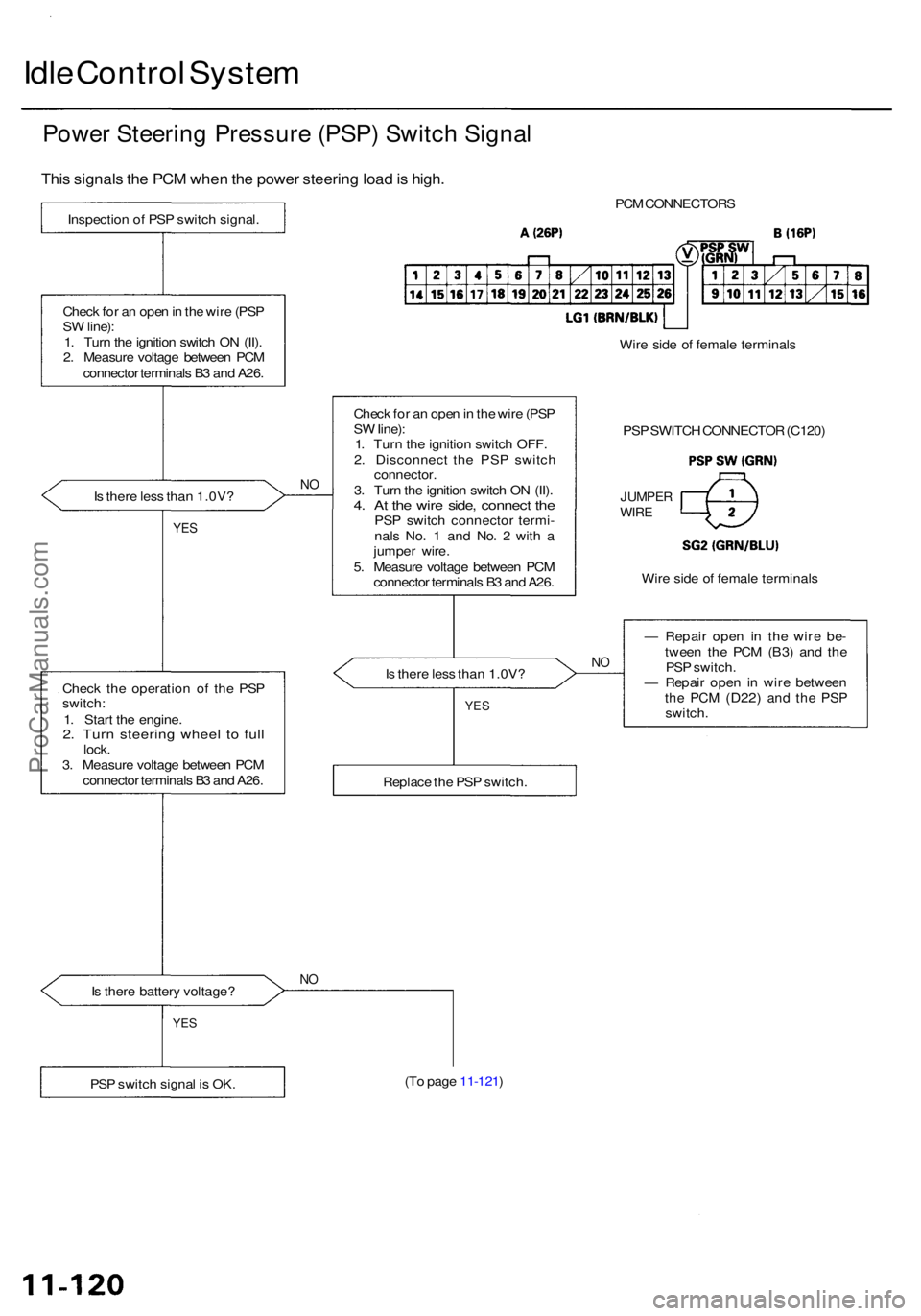
Idle Contro l Syste m
Power Steerin g Pressur e (PSP ) Switc h Signa l
This signal s th e PC M whe n th e powe r steerin g loa d is high .
Inspectio n o f PS P switc h signal .
Chec k fo r a n ope n in th e wir e (PS P
S W line) :
1 . Tur n th e ignitio n switc h O N (II) .
2 . Measur e voltag e betwee n PC M
connecto r terminal s B 3 an d A26 .
I s ther e les s tha n 1.0V ?
NO
YE S
Chec k th e operatio n o f th e PS P
switch :
1 . Star t th e engine .
2. Tur n steerin g whee l t o ful llock .
3 . Measur e voltag e betwee n PC M
connecto r terminal s B 3 an d A26 .
I s ther e batter y voltage ?
NO
PC M CONNECTOR S
Chec k fo r a n ope n in th e wir e (PS P
S W Iine) :
1 . Tur n th e ignitio n switc h OFF .
2 . Disconnec t th e PS P switc h
connector .
3 . Tur n th e ignitio n switc h O N (II) .
4. A t th e wir e side , connec t th ePS P switc h connecto r termi -
nal s No . 1 an d No . 2 wit h a
jumpe r wire .
5 . Measur e voltag e betwee n PC M
connecto r terminal s B 3 an d A26 . Wir
e sid e o f femal e terminal s
PS P SWITC H CONNECTO R (C120 )
JUMPE RWIRE
Wire sid e o f femal e terminal s
I s ther e les s tha n 1.0V ?
NO
— Repai r ope n i n th e wire be-
twee n th e PC M (B3 ) an d th e
PS P switch .
— Repai r ope n i n wir e betwee n
the PC M (D22 ) and th e PS Pswitch .
(T o pag e 11-121 )
PS P switc h signa l i s OK .
YES
Replac e th e PS P switch .
YES
ProCarManuals.com
Page 620 of 1954
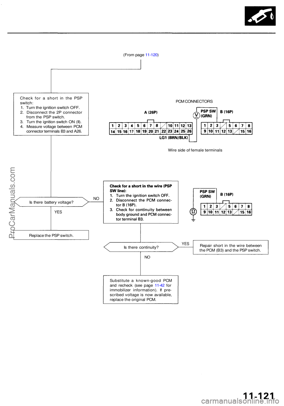
(From pag e 11-120 )
Chec k fo r a shor t i n th e PS P
switch :
1. Tur n th e ignitio n switc h OFF .2. Disconnec t th e 2 P connecto r
fro m th e PS P switch .
3 . Tur n th e ignitio n switc h O N (II) .
4 . Measur e voltag e betwee n PC M
connecto r terminal s B 3 an d A26 .
I s ther e batter y voltage ?
NO
PC M CONNECTOR S
Wir e sid e o f femal e terminal s
I s ther e continuity ? Repai
r shor t i n th e wir e betwee n
th e PC M (B3 ) an d th e PS P switch .
NO
Substitut e a known-goo d PC M
an d rechec k (se e pag e 11-42 fo r
immobilize r information) . I f pre -
scribe d voltag e i s no w available ,
replac e th e origina l PCM .
YES
Replac e th e PS P switch .
YES
ProCarManuals.com