ACURA RL KA9 1996 Service Repair Manual
Manufacturer: ACURA, Model Year: 1996, Model line: RL KA9, Model: ACURA RL KA9 1996Pages: 1954, PDF Size: 61.44 MB
Page 621 of 1954
Idle Contro l Syste m
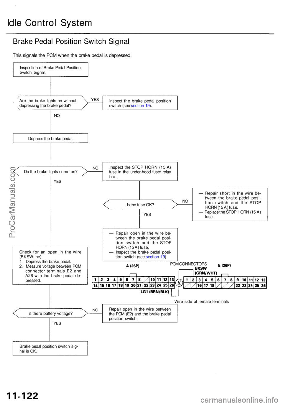
Brake Peda l Positio n Switc h Signa l
Are th e brak e light s o n withou t
depressin g th e brak e pedal ? Inspec
t th e brak e peda l positio n
switc h (se e sectio n 19 ).
N O
Depres s th e brak e pedal .
D o th e brak e light s com e on ?
YES
Is th e fus e OK ?NO
Chec k fo r a n ope n i n th e wir e
(BKS W line) :
1 . Depres s th e brak e pedal .
2 . Measur e voltag e betwee n PC M
connecto r terminal s E 2 an d
A2 6 wit h th e brak e peda l de -
pressed . —
Repai r shor t i n th e wire be-
twee n th e brak e peda l posi -
tio n switc h an d th e STO P
HOR N (1 5 A ) fuse .
— Replac e th e STO P HOR N (1 5 A )
fuse .
Wire sid e o f femal e terminal s
I s ther e batter y voltage ? Repai
r ope n in th e wir e betwee n
th e PC M (E2 ) an d th e brak e peda l
positio n switch .
Brak e peda l positio n switc h sig -
nal i s OK .
YES
NO
— Repai r ope n i n th e wir e be -
twee n th e brak e peda l posi -
tio n switc h an d th e STO P
HOR N (1 5 A ) fuse .
— Inspec t th e brak e peda l posi -
tio n switc h (se e sectio n 19 ).
PC M CONNECTOR S
YES
NOInspec t th e STO P HOR N (1 5 A )
fus e i n th e under-hoo d fuse / rela y
box.
YES
Inspectio n o f Brak e Peda l Positio n
Switc h Signal .
This signal s th e PC M whe n th e brak e peda l i s depressed .
ProCarManuals.com
Page 622 of 1954
Idle Ai r Contro l Therma l Valv e
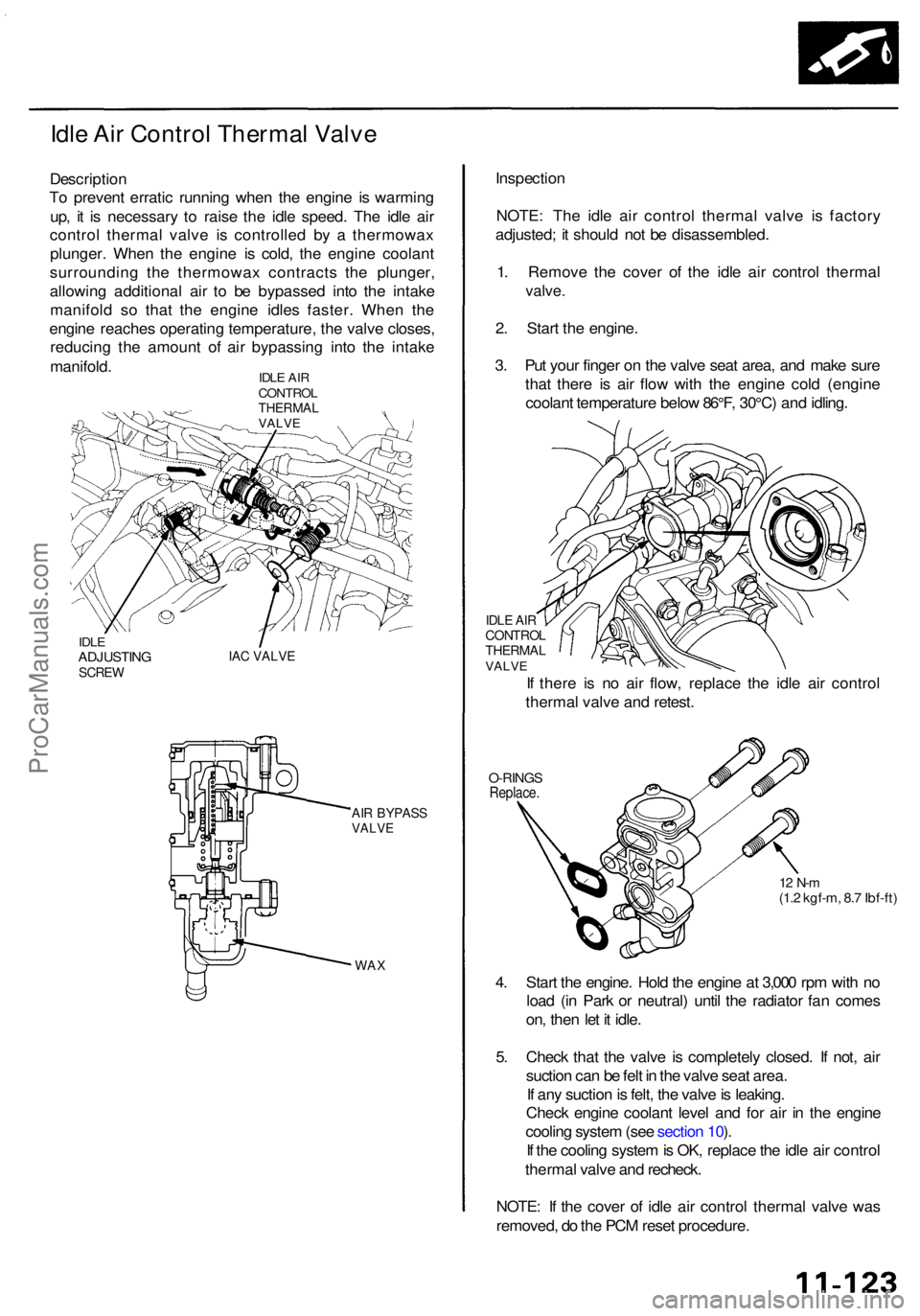
Descriptio n
T o preven t errati c runnin g whe n th e engin e i s warmin g
up , i t i s necessar y t o rais e th e idl e speed . Th e idl e ai r
contro l therma l valv e i s controlle d b y a thermowa x
plunger . Whe n th e engin e i s cold , th e engin e coolan t
surroundin g th e thermowa x contract s th e plunger ,
allowin g additiona l ai r t o b e bypasse d int o th e intak e
manifol d s o tha t th e engin e idle s faster . Whe n th e
engin e reache s operatin g temperature , th e valv e closes ,
reducin g th e amoun t o f ai r bypassin g int o th e intak e
manifold .
IDLE AI R
CONTRO L
THERMA LVALVE
IDLEADJUSTIN GSCREWIAC VALV E
AIR BYPAS SVALVE
WAX
Inspectio n
NOTE : Th e idl e ai r contro l therma l valv e i s factor y
adjusted ; i t shoul d no t b e disassembled .
1 . Remov e th e cove r o f th e idl e ai r contro l therma l
valve.
2. Star t th e engine .
3 . Pu t you r finge r o n th e valv e sea t area , an d mak e sur e
tha t ther e i s ai r flo w wit h th e engin e col d (engin e
coolan t temperatur e belo w 86°F , 30°C ) an d idling .
O-RING SReplace .
12 N- m(1.2 kgf-m , 8. 7 Ibf-ft )
4. Star t th e engine . Hol d th e engin e a t 3,00 0 rp m wit h n o
loa d (i n Par k o r neutral ) unti l th e radiato r fa n come s
on , the n le t i t idle .
5 . Chec k tha t th e valv e i s completel y closed . I f not , ai r
suctio n ca n b e fel t i n th e valv e sea t area .
I f an y suctio n is felt , th e valv e is leaking .
Chec k engin e coolan t leve l an d fo r ai r i n th e engin e
coolin g syste m (se e sectio n 10 ).
I f th e coolin g syste m is OK , replac e th e idl e ai r contro l
therma l valv e an d recheck .
NOTE : I f th e cove r o f idl e ai r contro l therma l valv e wa s
removed , d o th e PC M rese t procedure .
IDLE AI RCONTRO LTHERMALVALVE
If ther e i s n o ai r flow , replac e th e idl e ai r contro l
therma l valv e an d retest .
ProCarManuals.com
Page 623 of 1954
Idle Contro l Syste m
Idle Spee d Settin g
Inspection/Adjustmen t
NOTE:
• Befor e settin g th e idl e speed , chec k th e followin g
items:
— Th e MI L ha s no t bee n reporte d on .
— Ignitio n timin g
— Spar k plug s
— Ai r cleane r
— PC V syste m
• (Canada ) Depres s th e parkin g brak e pedal . Star t th e
engine , the n chec k tha t th e headlight s ar e off .
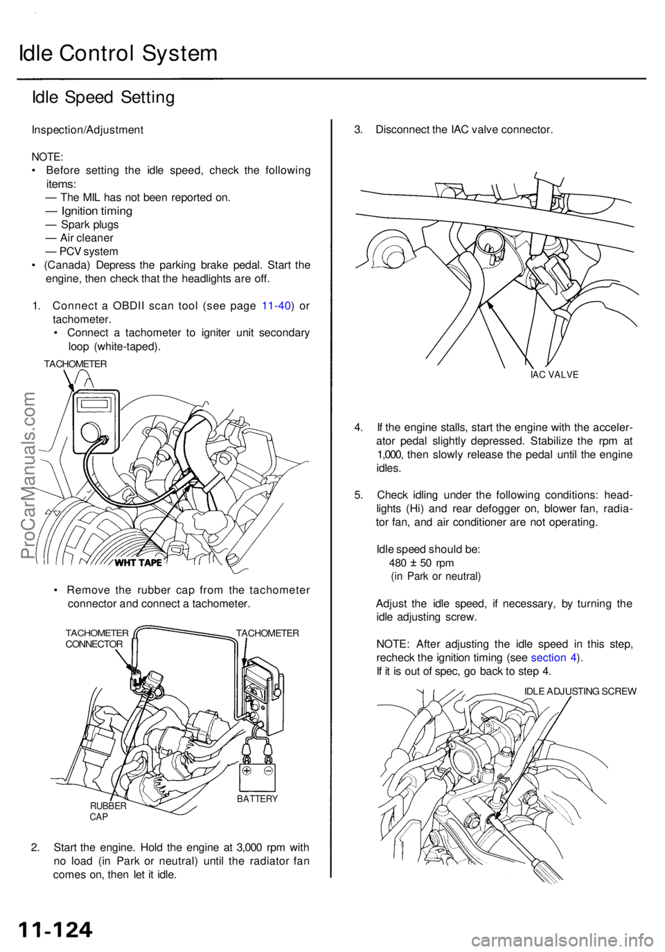
1 . Connec t a OBDI I sca n too l (se e pag e 11-40 ) o r
tachometer .
• Connec t a tachomete r t o ignite r uni t secondar y
loo p (white-taped) .
• Remov e th e rubbe r ca p fro m th e tachomete r
connecto r an d connec t a tachometer .
TACHOMETE RCONNECTORTACHOMETE R
RUBBERCAP
BATTER Y
2. Star t th e engine . Hol d th e engin e a t 3,00 0 rp m wit h
n o loa d (i n Par k o r neutral ) unti l th e radiato r fa n
come s on , the n le t i t idle . 3
. Disconnec t th e IA C valv e connector .
IAC VALV E
4. I f th e engin e stalls , star t th e engin e wit h th e acceler -
ato r peda l slightl y depressed . Stabiliz e th e rp m a t
1,000 , the n slowl y releas e th e peda l unti l th e engin e
idles .
5 . Chec k idlin g unde r th e followin g conditions : head -
light s (Hi ) an d rea r defogge r on , blowe r fan , radia -
to r fan , an d ai r conditione r ar e no t operating .
Idl e spee d shoul d be :
480 5 0 rp m
(in Par k o r neutral )
Adjust th e idl e speed , i f necessary , b y turnin g th e
idl e adjustin g screw .
NOTE : Afte r adjustin g th e idl e spee d i n thi s step ,
rechec k th e ignitio n timin g (se e sectio n 4 ).
I f i t i s ou t o f spec , g o bac k t o ste p 4 .
IDL E ADJUSTIN G SCRE W
TACHOMETE
R
ProCarManuals.com
Page 624 of 1954
6. Tur n th e ignitio n switc h OFF .
7. Reconnec t th e 2 P connecto r o n th e IA C valve , the n
d o th e PC M rese t procedure .
NOTE : Th e PC M memor y settin g i s neede d afte r
resettin g th e PCM .
8 . Restar t an d idl e th e engin e wit h no-loa d condition s
fo r on e minute , the n chec k th e idl e speed .
NOTE : (Canada ) Pul l th e parkin g brak e leve r up .
Star t th e engine , the n chec k tha t th e headlight s ar e
off.
Idle spee d shoul d be :
650 5 0 rp m
(in Par k o r neutral )
NOTE: I f th e idl e spee d i s no t withi n specification ,
se e Sympto m Char t o n pag e 11-44 .
ProCarManuals.com
Page 625 of 1954
PCM Memory Setting
NOTE: The PCM reset procedure and disconnecting the
battery or the BACK UP RADIO (7.5 A) fuse cancels the
PCM memory for idle control. The following procedure
is needed after the PCM reset procedure and reconnect-
ing the battery or the BACK UP RADIO (7.5 A) fuse.
1. Start the engine. Hold the engine at 3,000 rpm with
no load (in Park or neutral) until the radiator fan
comes on.
2. Let the engine idle for approx. 5 minutes under the
following conditions:
• Transmission in Park or neutral
• A/C switch OFF
• Headlights OFF
• Rear defogger OFFProCarManuals.com
Page 626 of 1954
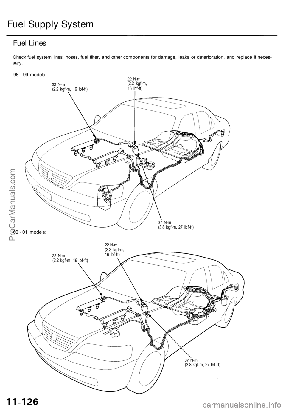
Fuel Supply System
Fuel Lines
Check fuel system lines, hoses, fuel filter, and other components for damage, leaks or deterioration, and replace if neces-
sary.
'96 - 99 models:
22 N-m
(2.2 kgf-m, 16 Ibf-ft)
22 N-m
(2.2 kgf-m,
16 Ibf-ft)
'00 - 01 models:
37 N-m
(3.8 kgf-m, 27 Ibf-ft)
22 N-m
(2.2 kgf-m, 16 Ibf-ft)
22 N-m
(2.2 kgf-m
16 Ibf-ft)
37 N-m
(3.8 kgf-m, 27 Ibf-ft)ProCarManuals.com
Page 627 of 1954
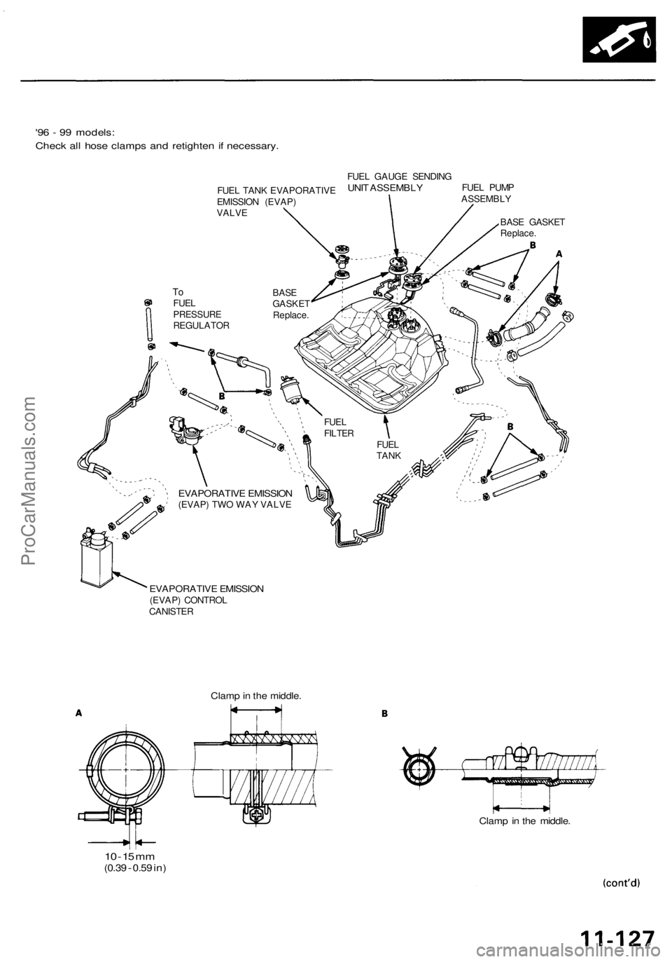
'96 - 99 models:
Check all hose clamps and retighten if necessary.
EVAPORATIVE EMISSION
(EVAP) TWO WAY VALVE
EVAPORATIVE EMISSION
(EVAP) CONTROL
CANISTER
10 -
15
mm
(0.39
-
0.59
in)
Clamp in the middle.
Clamp in the middle.
FUEL
TANK
FUEL
FILTER
To
FUEL
PRESSURE
REGULATOR
BASE
GASKET
Replace.
BASE GASKET
Replace.
FUEL PUMP
ASSEMBLY
FUEL GAUGE SENDING
UNIT ASSEMBLY
FUEL TANK EVAPORATIVE
EMISSION (EVAP)
VALVEProCarManuals.com
Page 628 of 1954
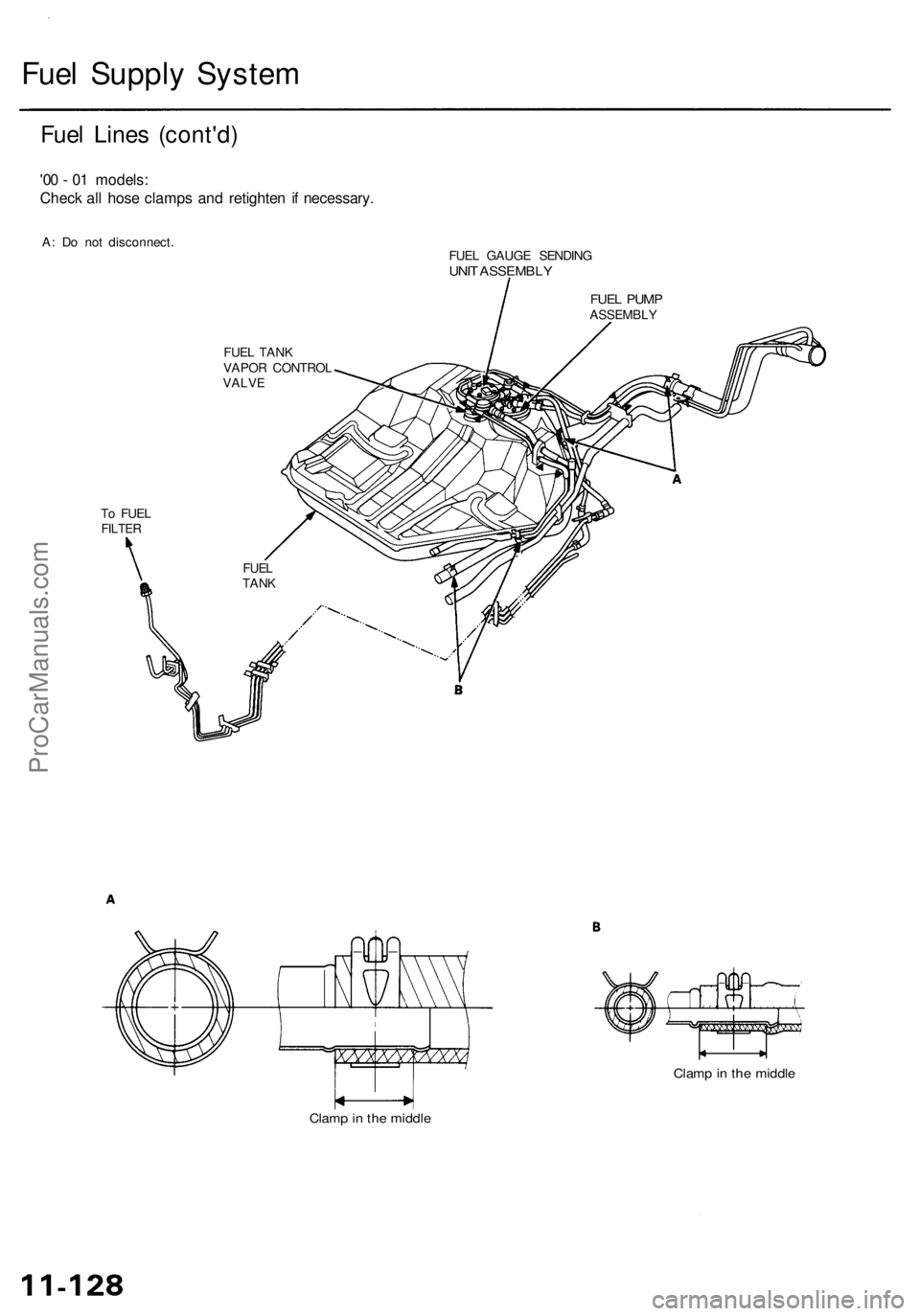
Fuel Supply System
Fuel Lines (cont'd)
'00 - 01 models:
Check all hose clamps and retighten if necessary.
A: Do not disconnect.
To FUEL
FILTER
FUEL TANK
VAPOR CONTROL
VALVE
FUEL GAUGE SENDING
UNIT ASSEMBLY
Clamp in the middle
Clamp in the middle
FUEL
TANK
FUEL PUMP
ASSEMBLYProCarManuals.com
Page 629 of 1954
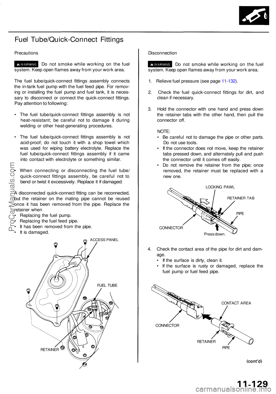
Fuel Tube/Quick-Connec t Fitting s
Precaution s
Do no t smok e whil e workin g o n th e fue l
system . Kee p ope n flame s awa y fro m you r wor k area .
Th e fue l tube/quick-connec t fitting s assembl y connect s
th e in-tan k fue l pum p wit h th e fue l fee d pipe . Fo r remov -
in g o r installin g th e fue l pum p an d fue l tank , i t i s neces -
sar y t o disconnec t o r connec t th e quick-connec t fittings .
Pay attentio n to following :
• Th e fue l tube/quick-connec t fitting s assembl y i s no t
heat-resistant ; b e carefu l no t t o damag e i t durin g
weldin g o r othe r heat-generatin g procedures .
• Th e fue l tube/quick-connec t fitting s assembl y i s no t
acid-proof ; d o no t touc h i t wit h a sho p towe l whic h
wa s use d fo r wipin g batter y electrolyte . Replac e th e
fue l tube/quick-connec t fitting s assembl y i f i t cam e
int o contac t wit h electrolyt e o r somethin g similar .
• Whe n connectin g o r disconnectin g th e fue l tube /
quick-connec t fitting s assembly , b e carefu l no t t o
ben d o r twis t i t excessively . Replac e it i f damaged .
A disconnecte d quick-connec t fittin g ca n b e reconnected ,
bu t th e retaine r o n th e matin g pip e canno t b e reuse d
onc e i t ha s bee n remove d fro m th e pipe . Replac e th e
retaine r whe n
• Replacin g th e fue l pump .
• Replacin g th e fue l fee d pipe .
• I t ha s bee n remove d fro m th e pipe .
• I t i s damaged .
ACCESS PANE L
RETAINE R
Disconnectio n
D o no t smok e whil e workin g o n th e fue l
system . Kee p ope n flame s awa y fro m you r wor k area .
1 . Reliev e fue l pressur e (se e pag e 11-132 ).
2 . Chec k th e fue l quick-connec t fitting s fo r dirt , an d
clea n if necessary .
3 . Hol d th e connecto r wit h on e han d an d pres s dow n
th e retaine r tab s wit h th e othe r hand , the n pul l th e
connecto r off .
NOTE :
• B e carefu l no t t o damag e th e pip e o r othe r parts .
D o no t us e tools .
• I f th e connecto r doe s no t move , kee p th e retaine r
tab s presse d down , an d alternatel y pul l an d pus h
th e connecto r unti l i t come s of f easily .
• D o no t remov e th e retaine r fro m th e pipe ; onc e
removed , th e retaine r mus t b e replace d wit h a
ne w one .
LOCKIN G PAW L
RETAINE R TA B
PIPE
CONNECTO R
Press down .
4. Chec k th e contac t are a o f th e pip e fo r dir t an d dam -
age.
• I f th e surfac e i s dirty , clea n it .
• I f th e surfac e i s rust y o r damaged , replac e th e
fue l pum p o r fue l fee d pipe .
CONTAC T ARE A
CONNECTO R
RETAINER
PIPE
FUE L TUB E
ProCarManuals.com
Page 630 of 1954
Fuel Supply System
Fuel Tube/Quick-Connect Fittings (cont'd)
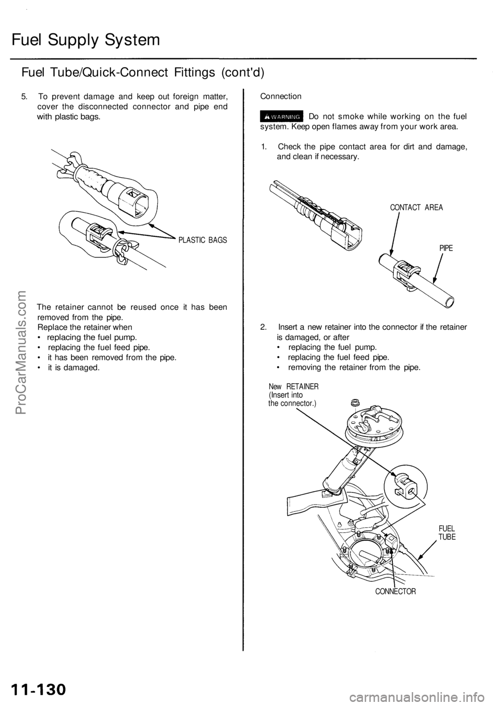
5. To prevent damage and keep out foreign matter,
cover the disconnected connector and pipe end
with plastic bags.
PLASTIC BAGS
The retainer cannot be reused once it has been
removed from the pipe.
Replace the retainer when
• replacing the fuel pump.
• replacing the fuel feed pipe.
• it has been removed from the pipe.
• it is damaged.
Connection
Do not smoke while working on the fuel
system. Keep open flames away from your work area.
1. Check the pipe contact area for dirt and damage,
and clean if necessary.
CONTACT AREA
PIPE
2. Insert a new retainer into the connector if the retainer
is damaged, or after
• replacing the fuel pump.
• replacing the fuel feed pipe.
• removing the retainer from the pipe.
New RETAINER
(Insert into
the connector.)
CONNECTOR
FUEL
TUBEProCarManuals.com