ACURA RL KA9 1996 Service Repair Manual
Manufacturer: ACURA, Model Year: 1996, Model line: RL KA9, Model: ACURA RL KA9 1996Pages: 1954, PDF Size: 61.44 MB
Page 641 of 1954
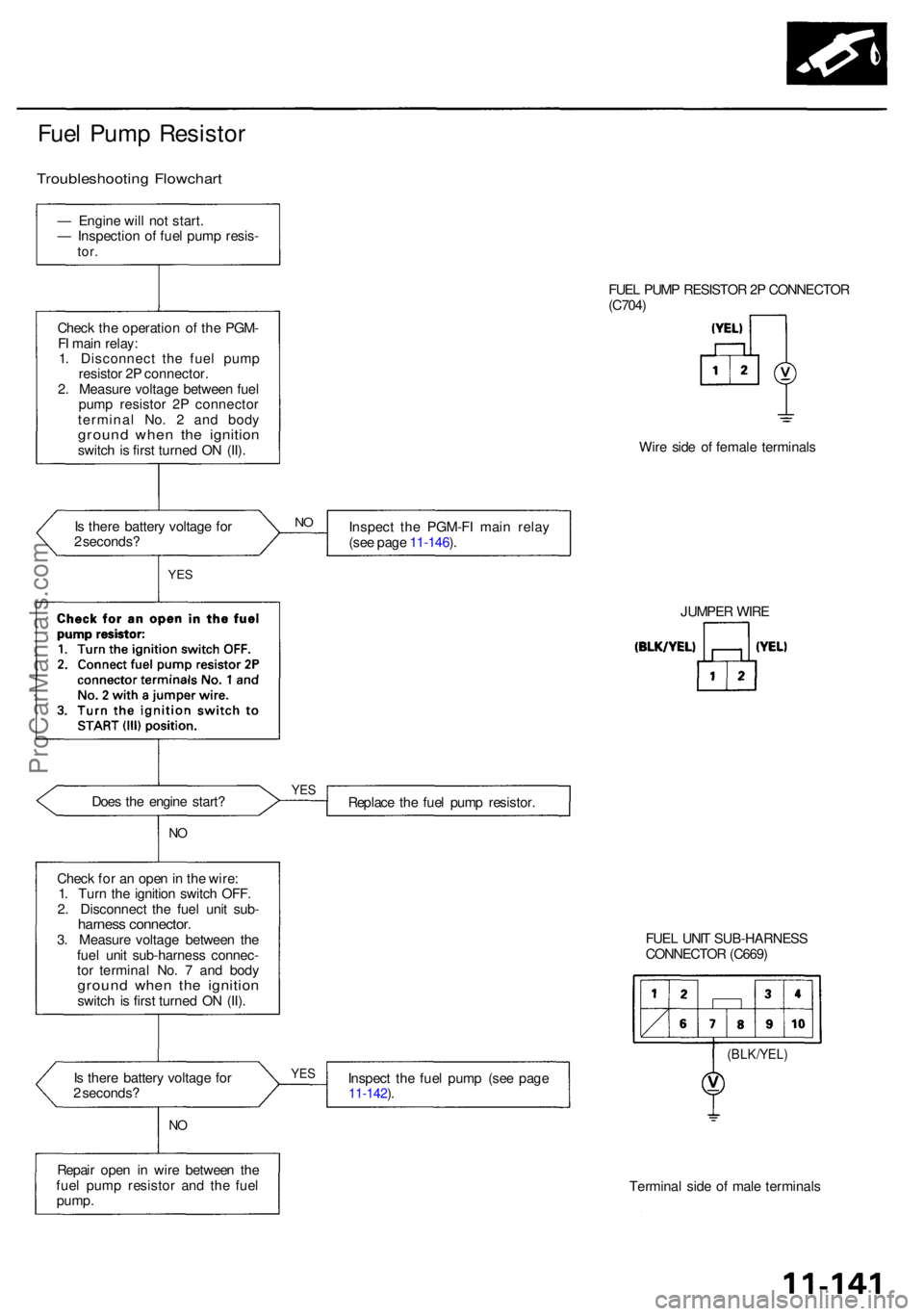
Fuel Pum p Resisto r
Troubleshootin g Flowchar t
Is ther e batter y voltag e fo r
2 seconds ?
Doe s th e engin e start ?
NO
Chec k fo r a n ope n in th e wire :
1 . Tur n th e ignitio n switc h OFF .
2 . Disconnec t th e fue l uni t sub -
harnes s connector .3. Measur e voltag e betwee n th e
fue l uni t sub-harnes s connec -
to r termina l No . 7 an d bod y
groun d whe n th e ignitio nswitch i s firs t turne d O N (II) .
I s ther e batter y voltag e fo r
2 seconds ? FUE
L PUM P RESISTO R 2P CONNECTO R
(C704 )
Wir e sid e o f femal e terminal s
Inspec t th e PGM-F I mai n rela y
(se e pag e 11-146 ).
Replac e th e fue l pum p resistor .
FUEL UNI T SUB-HARNES S
CONNECTO R (C669 )
(BLK/YEL )
Inspect th e fue l pum p (se e pag e11-142 ).
Termina l sid e o f mal e terminal s
Repai
r ope n i n wir e betwee n th e
fue l pum p resisto r an d th e fue l
pump .
YES
NO
YE S
JUMPE R WIR E
NO
YE S
Chec k th e operatio n o f th e PGM -
F I mai n relay :
1 . Disconnec t th e fue l pum p
resisto r 2 P connector .
2 . Measur e voltag e betwee n fue l
pum p resisto r 2 P connecto r
termina l No . 2 an d bod y
groun d whe n th e ignitio nswitch i s firs t turne d O N (II) .
—
Engin e wil l no t start .
— Inspectio n o f fue l pum p resis -
tor.
ProCarManuals.com
Page 642 of 1954
Fuel Suppl y Syste m
Fuel Filte r
Replacemen t
D o no t smok e whil e workin g o n fue l system .
Kee p ope n flam e awa y fro m you r wor k area .
• Whil e replacin g the fue l filter , be carefu l to kee p a safe
distanc e betwee n batter y terminal s an d an y tools .
Th e fue l filte r shoul d b e replace d wheneve r th e fue l pres -
sur e drop s belo w th e specifie d valu e [29 9 - 34 8 kP a
(3.0 5 - 3.5 5
kgf/cm2, 43 - 5 0 psi ) wit h th e fue l pressur e
regulato r vacuu m hos e disconnecte d an d pinched ] afte r
makin g sur e tha t th e fue l pum p an d th e fue l pressur e
regulator ar e OK .
1. Plac e a sho p towe l unde r an d aroun d th e fue l filter .
2 . Reliev e fue l pressur e (se e pag e 11-132 ).
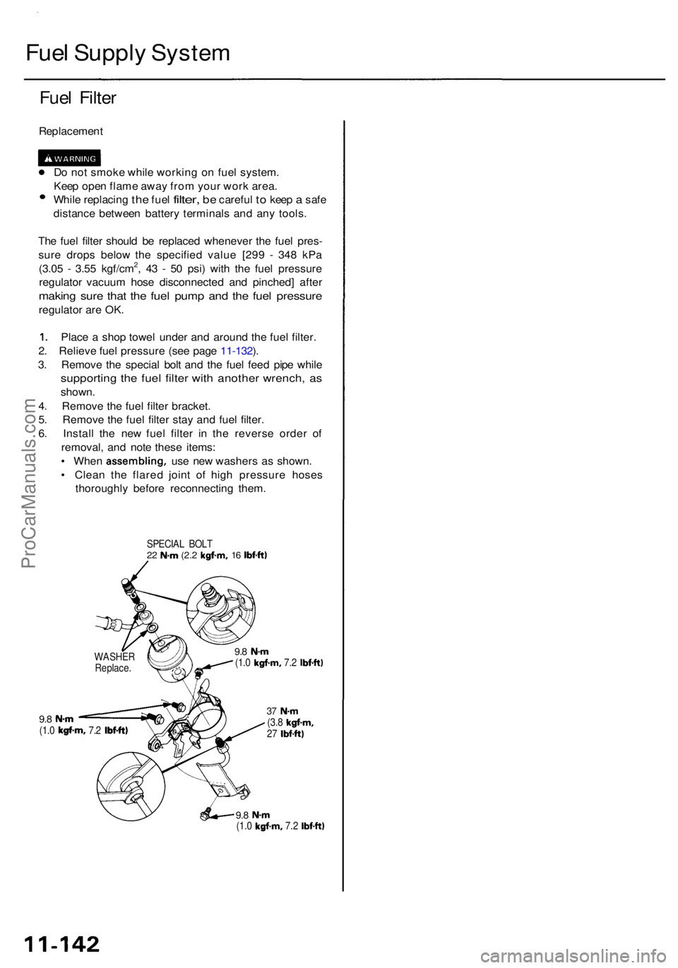
3 . Remov e th e specia l bol t an d th e fue l fee d pip e whil e
supportin g th e fue l filte r wit h anothe r wrench , a s
shown .
4 . Remov e th e fue l filte r bracket .
5 . Remov e th e fue l filte r sta y an d fue l filter .
6 . Instal l th e ne w fue l filte r i n th e revers e orde r of
removal , an d not e thes e items :
• Whe n assembling , use ne w washer s a s shown .
• Clea n th e flare d join t o f hig h pressur e hose s
thoroughl y befor e reconnectin g them .
SPECIA L BOL T22 N- m (2. 2 kgf-m , 16 Ibf-ft )
9.8 N- m(1.0 kgf-m , 7.2 Ibf-ft )
9.8 N- m(1.0 kgf-m , 7.2 Ibf-ft )
37 N- m(3.8 kgf-m ,27 Ibf-ft )
9.8 N- m(1.0 kgf-m , 7.2 Ibf-ft )
WASHE R
Replace .
ProCarManuals.com
Page 643 of 1954
Fuel Suppl y Syste m
Fuel Pum p
Testin g
Do no t smok e durin g th e test . Kee p ope n
flam e awa y fro m you r wor k area .
I f yo u suspec t a proble m wit h th e fue l pump , chec k tha t
th e fue l pum p actuall y runs ; whe n it i s ON , yo u wil l hea r
som e nois e i f yo u hol d you r ea r t o th e fue l fil l por t wit h
th e fue l fil l cap removed . Th e fue l pum p shoul d ru n fo r 2
second s whe n ignitio n switc h i s firs t turne d on . I f th e
fue l pum p doe s no t mak e noise , chec k a s follows :
1 . Remov e th e rea r sea t cushio n (se e sectio n 20 ).
2 . Disconnec t th e 10 P connector .
CAUTION :
Be sur e to tur n the ignitio n switch OFF
befor e disconnectin g th e wires .
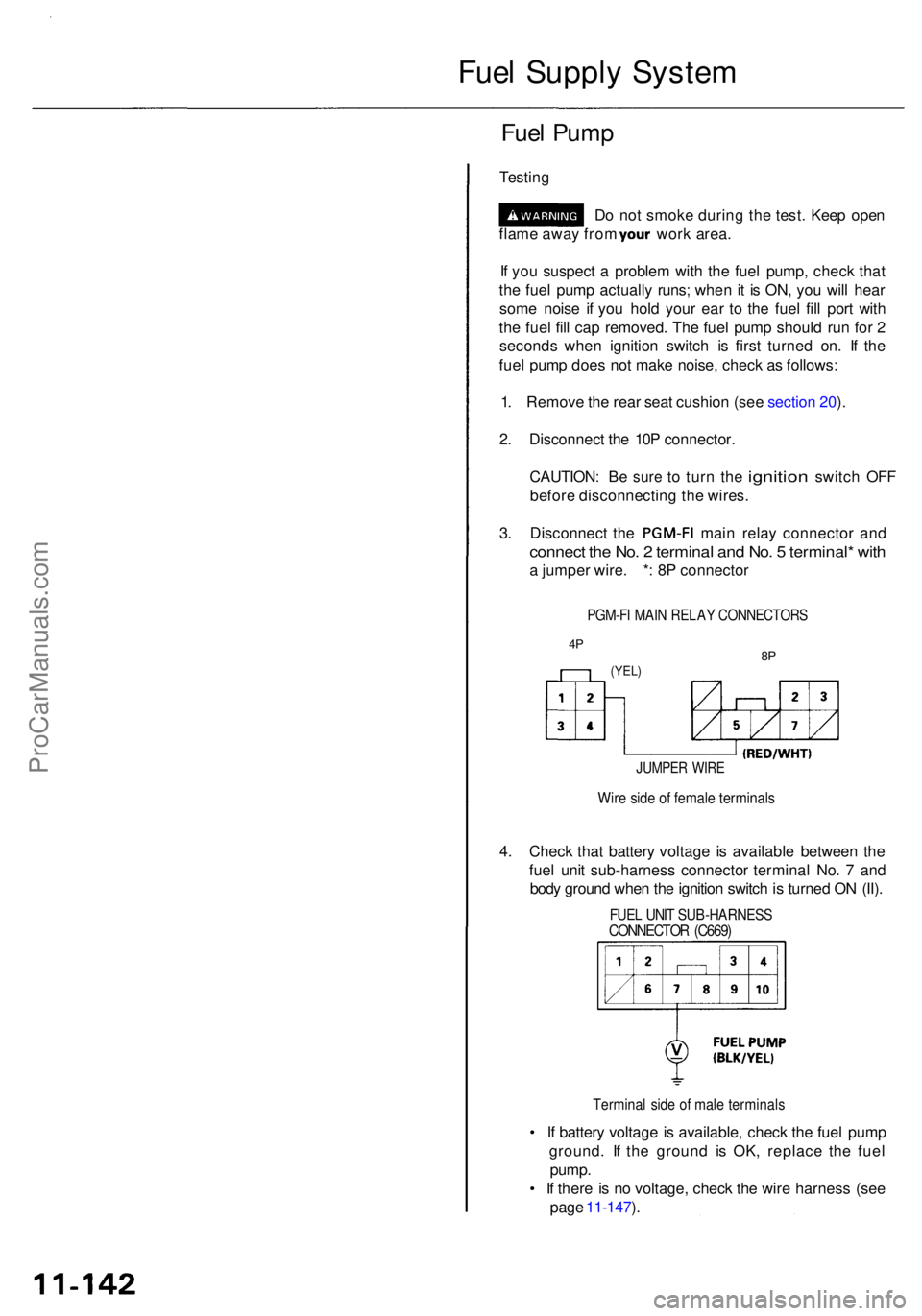
3. Disconnec t th e PGM-F I main rela y connecto r an d
connec t th e No . 2 termina l an d No . 5 terminal * wit h
a jumpe r wire . * : 8 P connecto r
PGM-FI MAI N RELA Y CONNECTOR S
4P8P(YEL )
JUMPE R WIR E
Wire sid e o f femal e terminal s
4. Chec k tha t batter y voltag e i s availabl e betwee n th e
fue l uni t sub-harnes s connecto r termina l No . 7 an d
bod y groun d whe n th e ignitio n switc h is turne d O N (II) .
FUE L UNI T SUB-HARNES SCONNECTOR (C669 )
Termina l sid e o f mal e terminal s
• I f batter y voltag e is available , chec k th e fue l pum p
ground . I f th e groun d i s OK , replac e th e fue l
pump .
• I f ther e is n o voltage , chec k th e wir e harnes s (se e
pag e 11-147 ).
ProCarManuals.com
Page 644 of 1954
Replacement
Do no t smok e whil e workin g o n fue l sys -
tem. Kee p ope n flame s awa y fro m you r wor k area .
1. Remov e th e rea r sea t cushio n (se e sectio n 20 ).
2 . Remov e th e acces s pane l fro m th e floor .
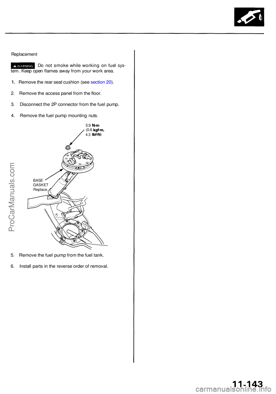
3 . Disconnec t th e 2 P connecto r fro m th e fue l pump .
4 . Remov e th e fue l pum p mountin g nuts .
5.9 N- m(0.6 kgf-m ,4.3 Ibf-ft )
5. Remov e th e fue l pum p fro m th e fue l tank .
6 . Instal l part s in th e revers e orde r o f removal .
BASEGASKE TReplace .
ProCarManuals.com
Page 645 of 1954
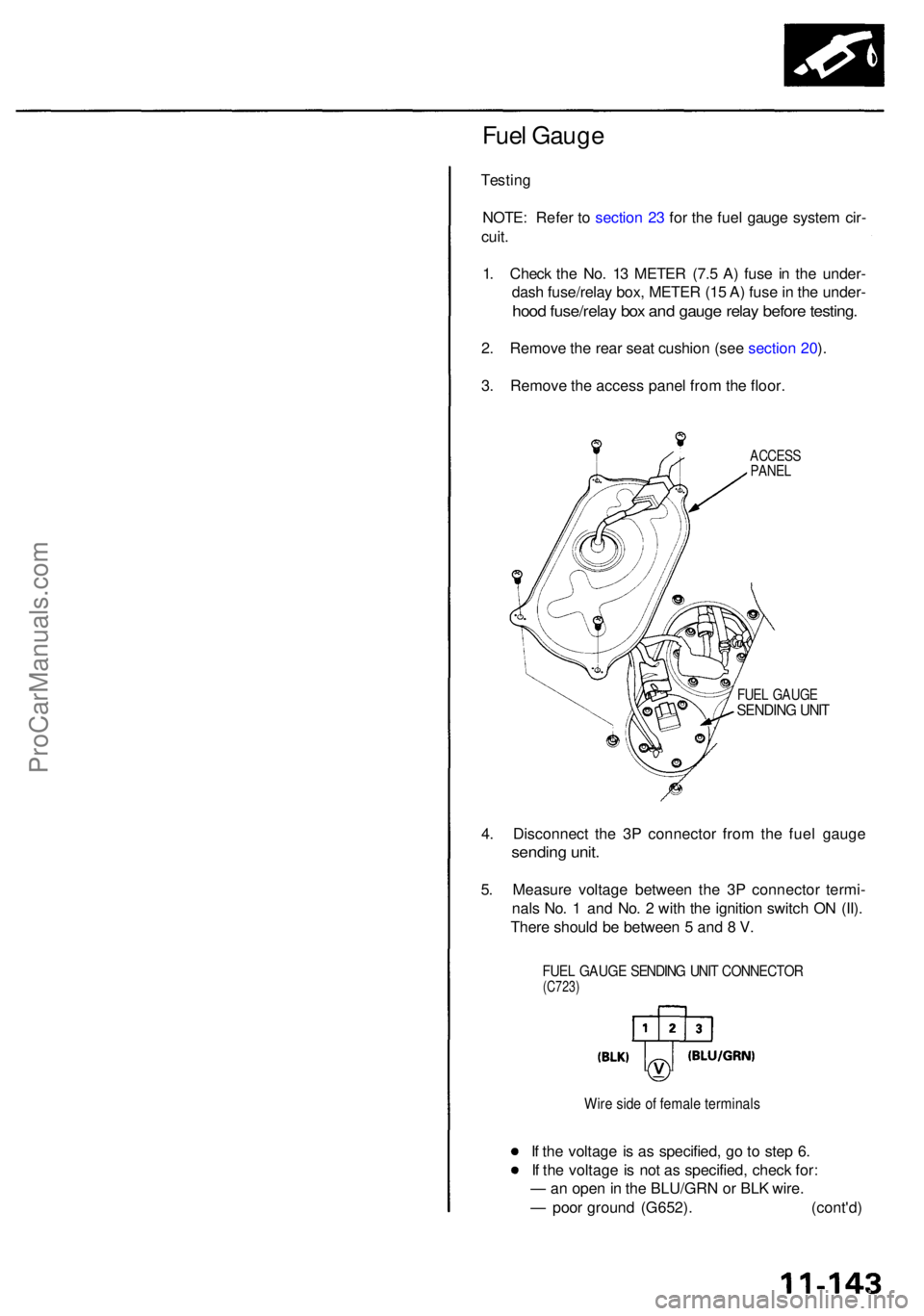
Fuel Gaug e
Testin g
NOTE : Refe r t o sectio n 2 3 fo r th e fue l gaug e syste m cir -
cuit .
1 . Chec k th e No . 1 3 METE R (7. 5 A ) fus e i n th e under -
dash fuse/rela y box , METE R (1 5 A ) fus e in th e under -
hood fuse/rela y bo x an d gaug e rela y befor e testing .
2. Remov e th e rea r sea t cushio n (se e sectio n 20 ).
3 . Remov e th e acces s pane l fro m th e floor .
ACCES SPANEL
FUEL GAUG ESENDIN G UNI T
4. Disconnec t th e 3 P connecto r fro m th e fue l gaug e
sendin g unit .
5. Measur e voltag e betwee n th e 3 P connecto r termi -
nal s No . 1 an d No . 2 wit h th e ignitio n switc h O N (II) .
Ther e shoul d b e betwee n 5 an d 8 V .
FUE L GAUG E SENDIN G UNI T CONNECTO R(C723)
Wire sid e o f femal e terminal s
If th e voltag e is a s specified , g o t o ste p 6 .
I f th e voltag e is no t a s specified , chec k for :
— an ope n in th e BLU/GR N o r BL K wire .
— poo r groun d (G652) . (cont'd )
ProCarManuals.com
Page 646 of 1954
Fuel Suppl y Syste m
Fuel Gaug e (cont'd )
6. Tur n th e ignitio n switc h OFF .
7 . Attac h a jumpe r wir e betwee n th e No . 1 an d No . 2
terminals , the n tur n th e ignitio n switc h O N (II) .
8 . Chec k tha t th e pointe r o f th e fue l gaug e start s mov -
ing towar d th e "F " mark .
CAUTION : Tur n th e ignitio n switc h OF F befor e th e
pointe r reache s "F " o n th e gaug e dial . Failur e to d o
s o ma y damag e th e fue l gauge .
NOTE : Th e fue l gaug e is a bobbi n (cross-coil )
type,
henc e th e fue l leve l i s continuousl y indicate d eve n
whe n th e ignitio n switc h i s OFF , an d th e pointe r
moves mor e slowl y tha n tha t o f a bimeta l type .
• I f th e pointe r o f th e fue l gaug e doe s no t mov e a t
all , replac e th e gauge .
• I f th e gaug e i s OK , inspec t th e fue l gaug e send -
ing unit .
ProCarManuals.com
Page 647 of 1954
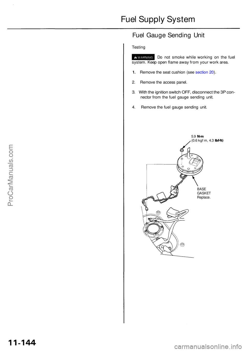
Fuel Suppl y Syste m
system . Kee p ope n flam e awa y fro m you r wor k area .
1. Remov e th e sea t cushio n (se e sectio n 20 ).
2 . Remov e th e acces s panel .
3. Wit h th e ignitio n switc h OFF , disconnec t th e 3 P con -
necto r fro m th e fue l gaug e sendin g unit .
4 . Remov e th e fue l gaug e sendin g unit .
5.9 N- m(0.6 kg f m , 4. 3 Ibf-ft )
BASEGASKE TReplace .
Fuel Gaug e Sendin g Uni t
Testin g
Do no t smok e whil e workin g o n th e fue l
ProCarManuals.com
Page 648 of 1954
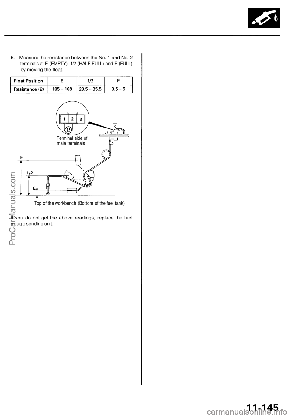
5. Measure the resistance between the No. 1 and No. 2
terminals at E (EMPTY), 1/2 (HALF FULL) and F (FULL)
by moving the float.
Terminal side of
male terminals
Top of the workbench (Bottom of the fuel tank)
If you do not get the above readings, replace the fuel
gauge sending unit.ProCarManuals.com
Page 649 of 1954
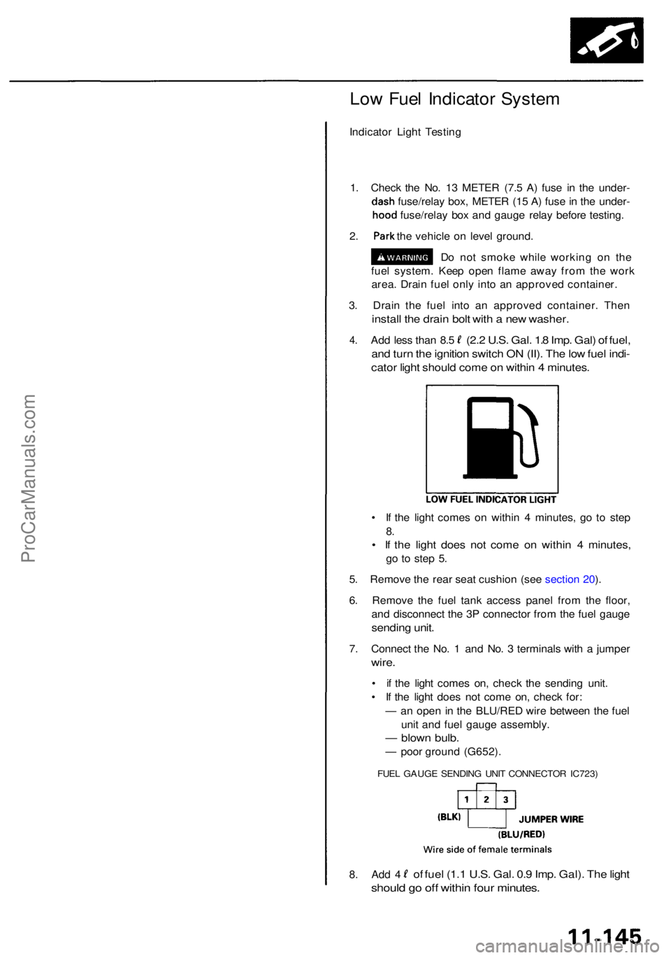
Low Fue l Indicato r Syste m
Indicato r Ligh t Testin g
1 . Chec k th e No . 1 3 METE R (7. 5 A ) fus e i n th e under -
dash fuse/rela y box , METE R (1 5 A ) fus e in th e under -
hood fuse/rela y bo x an d gaug e rela y befor e testing .
2. Par k the vehicl e o n leve l ground .
D o no t smok e whil e workin g o n th e
fue l system . Kee p ope n flam e awa y fro m th e wor k
area . Drai n fue l onl y int o a n approve d container .
• I f th e ligh t come s o n withi n 4 minutes , g o t o ste p
8.
• I f th e ligh t doe s no t com e o n withi n 4 minutes ,
go t o ste p 5 .
5 . Remov e th e rea r sea t cushio n (se e sectio n 20 ).
6 . Remov e th e fue l tan k acces s pane l fro m th e floor ,
an d disconnec t th e 3 P connecto r fro m th e fue l gaug e
sendin g unit .
7. Connec t th e No . 1 an d No . 3 terminal s wit h a jumpe r
wire.
• i f th e ligh t come s on , chec k th e sendin g unit .
• I f th e ligh t doe s no t com e on , chec k for :
— an ope n in th e BLU/RE D wir e betwee n th e fue l
uni t an d fue l gaug e assembly .
— blow n bulb .
— poo r groun d (G652) .
FUEL GAUG E SENDIN G UNI T CONNECTO R IC723 )
should g o of f withi n fou r minutes .
8. Ad d 4of fue l (1. 1 U.S . Gal . 0. 9 Imp . Gal) . Th e ligh t
3. Drai n th e fue l int o a n approve d container . The n
instal l th e drai n bol t wit h a ne w washer .
4.
an d tur n th e ignitio n switc h O N (II) . Th e lo w fue l indi -
cato r ligh t shoul d com e o n withi n 4 minutes .
Add les s tha n 8. 5(2. 2 U.S . Gal . 1. 8 Imp . Gal ) o f fuel ,
ProCarManuals.com
Page 650 of 1954
Fuel Suppl y Syste m
PGM-F I Mai n Rela y
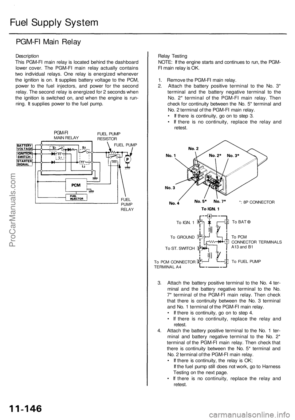
Descriptio n
Thi s PGM-F I mai n rela y is locate d behin d th e dashboar d
lowe r cover . Th e PGM-F I mai n rela y actuall y contain s
tw o individua l relays . On e rela y i s energize d wheneve r
th e ignitio n i s on . I t supplie s batter y voltag e t o th e PCM ,
powe r t o th e fue l injectors , an d powe r fo r th e secon d
relay . Th e secon d rela y is energize d fo r 2 second s whe n
th e ignitio n i s switche d on , an d whe n th e engin e i s run -
ning . I t supplie s powe r t o th e fue l pump .
PGM-F IMAIN RELA Y
FUELPUM PRELA Y
Relay Testin g
NOTE : I f th e engin e start s an d continue s to run , th e PGM -
F I mai n rela y is OK .
1 . Remov e th e PGM-F I mai n relay .
2 . Attac h th e batter y positiv e termina l t o th e No . 3 *
termina l an d th e batter y negativ e termina l t o th e
No . 2 * termina l o f th e PGM-F I mai n relay . The n
chec k fo r continuit y betwee n th e No . 5 * termina l an d
No . 2 termina l o f th e PGM-F I mai n relay .
• I f ther e i s continuity , g o o n t o ste p 3 .
• I f ther e i s n o continuity , replac e th e rela y an d
retest .
*: 8 P CONNECTO R
T o FUE L PUM P
3. Attac h th e batter y positiv e termina l t o th e No . 4 ter -
mina l an d th e batter y negativ e termina l t o th e No .
7 * termina l o f th e PGM-F I mai n relay . The n chec k
tha t ther e i s continuit y betwee n th e No . 3 termina l
an d No . 1 termina l o f th e PGM-F I mai n relay .
• I f ther e i s continuity , g o o n t o ste p 4 .
• I f ther e i s n o continuity , replac e th e rela y an d
retest .
4 . Attac h th e batter y positiv e termina l t o th e No . 1 ter -
mina l an d batter y negativ e termina l t o th e No . 2 *
termina l o f th e PGM-F I mai n relay . The n chec k tha t
ther e i s continuit y betwee n th e No . 5 * termina l an d
No . 2 termina l o f th e PGM-F I mai n relay .
• I f ther e i s continuity , th e rela y i s OK ;
I f th e fue l pum p stil l doe s no t work , g o to Harnes s
Testin g o n th e nex t page .
• I f ther e i s n o continuity , replac e th e rela y an d
retest .
To PC M CONNECTO R
TERMINA L A 4
To ST . SWITC H
To GROUN D
To IGN . 1To BA T
To PC MCONNECTO R TERMINAL SA13 an d B 1
FUE L PUM PRESISTO R
FUEL PUM P
ProCarManuals.com