ACURA RL KA9 1996 Service Repair Manual
Manufacturer: ACURA, Model Year: 1996, Model line: RL KA9, Model: ACURA RL KA9 1996Pages: 1954, PDF Size: 61.44 MB
Page 781 of 1954
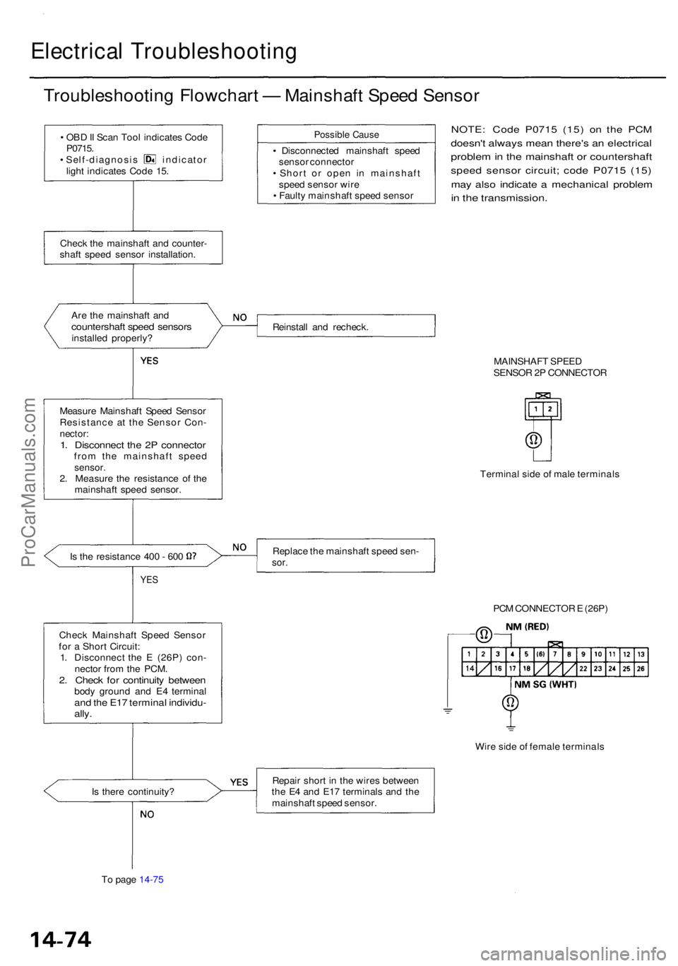
Electrical Troubleshootin g
Troubleshooting Flowchar t — Mainshaf t Spee d Senso r
• OB D II Sca n Too l indicate s Cod e
P0715 .
• Self-diagnosi s indicato r
ligh t indicate s Cod e 15 .
Chec k th e mainshaf t an d counter -
shaf t spee d senso r installation .
Ar e th e mainshaf t an d
countershaf t spee d sensor sinstalled properly ?
Measur e Mainshaf t Spee d Senso r
Resistanc e a t th e Senso r Con -
nector :1. Disconnec t th e 2 P connecto rfrom th e mainshaf t spee dsensor .2. Measur e th e resistanc e o f th e
mainshaf t spee d sensor .
Is th e resistanc e 40 0 - 60 0
YE S
Chec k Mainshaf t Spee d Senso r
fo r a Shor t Circuit :
1 . Disconnec t th e E (26P ) con -
necto r fro m th e PCM .
2. Chec k fo r continuit y betwee nbody groun d an d E 4 termina land th e E1 7 termina l individu -ally.
Possibl e Caus e
• Disconnecte d mainshaf t spee d
senso r connecto r
• Shor t o r ope n i n mainshaf t
spee d senso r wir e
• Fault y mainshaf t spee d senso r
NOTE: Cod e P071 5 (15 ) o n th e PC M
doesn' t alway s mea n there' s a n electrica l
problem in th e mainshaf t o r countershaf t
speed senso r circuit ; cod e P071 5 (15 )
may als o indicat e a mechanica l proble m
in th e transmission .
Reinstall an d recheck .
MAINSHAFT SPEE D
SENSO R 2P CONNECTO R
Termina l sid e o f mal e terminal s
Replac e th e mainshaf t spee d sen -
sor.
Wir e sid e o f femal e terminal s
I s ther e continuity ?
T o pag e 14-7 5 Repai
r shor t i n th e wire s betwee n
th e E 4 an d E1 7 terminal s an d th e
mainshaf t spee d sensor . PC
M CONNECTO R E (26P )
ProCarManuals.com
Page 782 of 1954
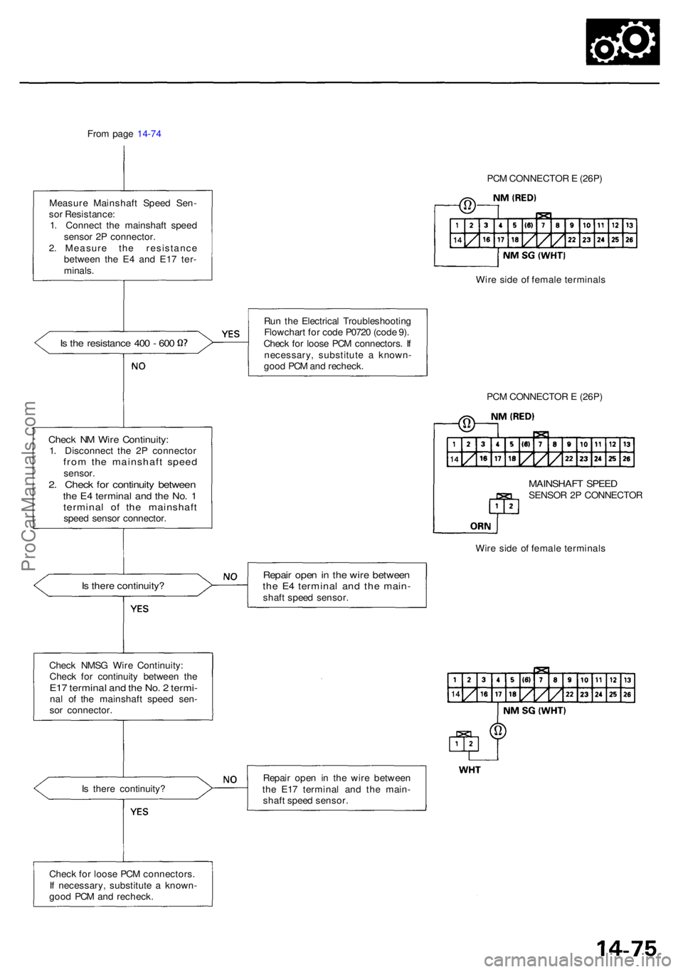
From pag e 14-7 4
Measur e Mainshaf t Spee d Sen -
so r Resistance :
1 . Connec t th e mainshaf t spee d
senso r 2 P connector .
2 . Measur e th e resistanc e
betwee n th e E 4 an d E1 7 ter -
minals .
Is th e resistanc e 40 0 - 60 0
Chec k N M Wir e Continuity :1. Disconnec t th e 2 P connecto rfrom th e mainshaf t spee dsensor .2. Chec k fo r continuit y betwee nthe E 4 termina l an d th e No . 1termina l o f th e mainshaf tspeed senso r connector .
Is ther e continuity ?
Check NMS G Wir e Continuity :
Chec k fo r continuit y betwee n th e
E17 termina l an d th e No . 2 termi -nal o f th e mainshaf t spee d sen -
so r connector . Wir
e sid e o f femal e terminal s
I s ther e continuity ?
Chec k fo r loos e PC M connectors .
I f necessary , substitut e a known -
goo d PC M an d recheck . Ru
n th e Electrica l Troubleshootin g
Flowchar t fo r cod e P072 0 (cod e 9) .
Chec k fo r loos e PC M connectors . I f
necessary , substitut e a known -
goo d PC M an d recheck .
MAINSHAF T SPEE DSENSO R 2 P CONNECTO R
Wir e sid e o f femal e terminal s
Repair ope n in th e wir e betwee nthe E 4 termina l an d th e main -shaft spee d sensor .
Repai r ope n i n th e wir e betwee n
th e E1 7 termina l an d th e main -
shaf t spee d sensor . PC
M CONNECTO R E (26P )
PC M CONNECTO R E (26P )
ProCarManuals.com
Page 783 of 1954
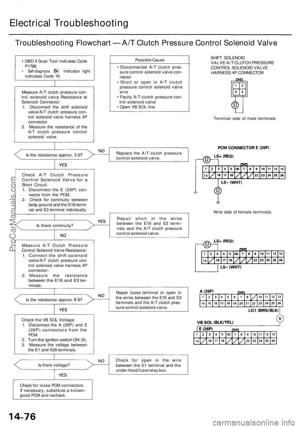
Electrical Troubleshootin g
Troubleshooting Flowchar t — A/ T Clutc h Pressur e Contro l Solenoi d Valv e
• OB D II Sca n Too l indicate s Cod e
P1768 .
• Self-diagnosi s indicator ligh t
indicate s Cod e 16 .
Measur e A/ T clutc h pressur e con -
tro l solenoi d valv e Resistanc e a t
Solenoi d Connector :
1 . Disconnec t th e shif t solenoi d
valve/A/ T clutc h pressur e con -
tro l solenoi d valv e harnes s 4 P
connector .
2 . Measur e th e resistanc e o f th e
A/ T clutc h pressur e contro l
solenoi d valve .
Is th e resistanc e approx . 5
Chec k A/ T Clutc h Pressur e
Control Solenoi d Valv e fo r aShor t Circuit :
1 . Disconnec t th e E (26P ) con -
necto r fro m th e PCM .
2 . Chec k fo r continuit y betwee n
body groun d an d th e E1 6 termi -nal an d E 3 termina l individually .
I s ther e continuity ?
Is th e resistanc e approx .
Chec k th e V B SO L Voltage :
1 . Disconnec t th e A (26P ) an d E
(26P ) connector s fro m th ePCM .2. Tur n th e ignitio n switc h O N (II) .3. Measur e th e voltag e betwee n
th e E 1 an d A2 6 terminals .
I s ther e voltage ?
Chec k fo r loos e PC M connectors .
I f necessary , substitut e a known -
goo d PC M an d recheck . Possibl
e Caus e
• Disconnecte d A/ T clutc h pres -
sur e contro l solenoi d valv e con -
necto r
• Shor t o r ope n i n A/ T clutc h
pressur e contro l solenoi d valv e
wir e
• Fault y A/ T clutc h pressur e con -
tro l solenoi d valv e
• Ope n V B SO L lin e
Replac e th e A/ T clutc h pressur e
contro l solenoi d valve .
Repai r shor t i n th e wire s
betwee n th e E1 6 an d E 3 termi -
nal s an d th e A/ T clutc h pressur e
contro l solenoi d valve .
Repai r loos e termina l o r ope n i n
th e wire s betwee n th e E1 6 an d E 3
terminal s an d th e A/ T clutc h pres -
sur e contro l solenoi d valve .
Chec k fo r ope n i n th e wir e
betwee n th e E 1 termina l an d th eunder-hoo d fuse/rela y box . SHIF
T SOLENOI D
VALVE/A/ T CLUTC H PRESSUR E
CONTRO L SOLENOI D VALV E
HARNES S 4 P CONNECTO R
Termina l sid e o f mal e terminal s
Wir e sid e o f femal e terminal s
Measur e A/ T Clutc h Pressur e
Contro l Solenoi d Valv e Resistance :
1. Connec t th e shif t solenoi dvalve/A/T clutc h pressur e con -
tro l solenoi d valv e harnes s 4 P
connector .
2 . Measur e th e resistanc e
between th e E1 6 an d E 3 ter -minals .
ProCarManuals.com
Page 784 of 1954
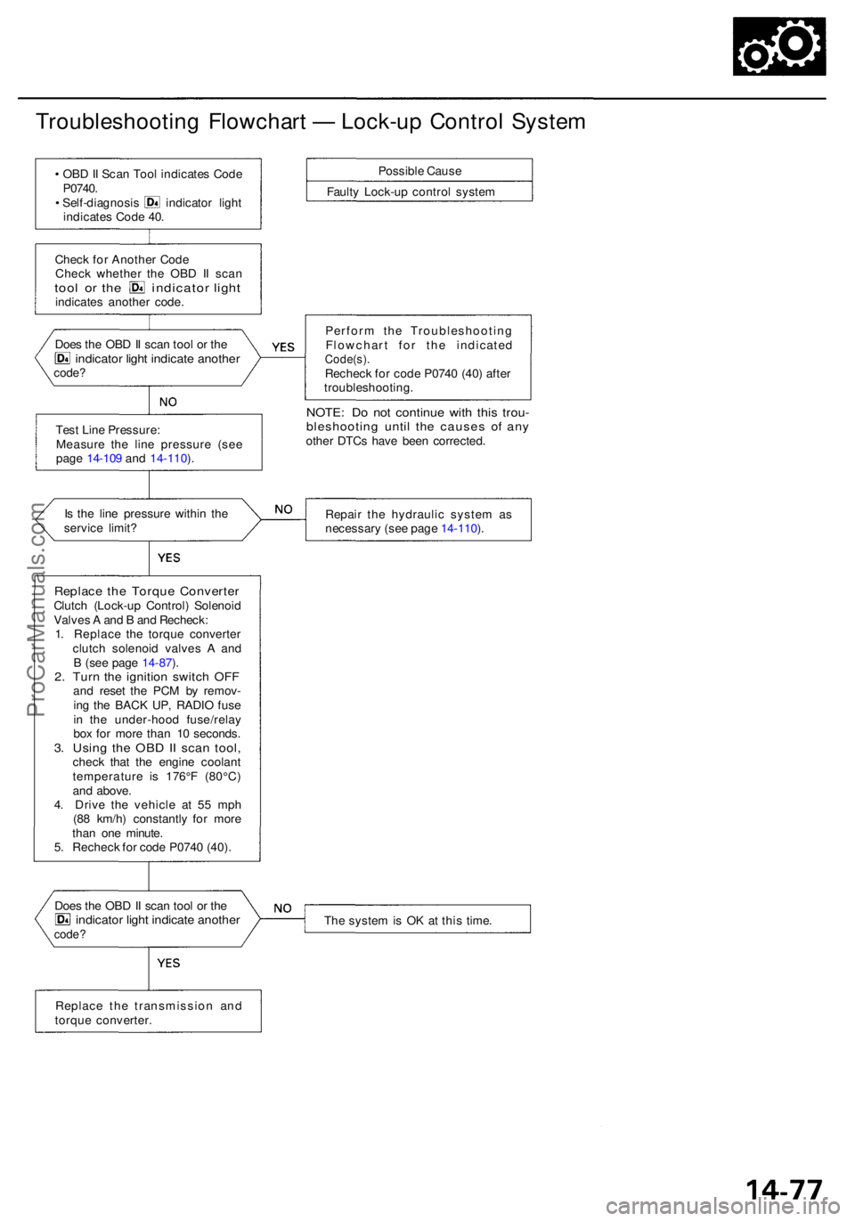
Troubleshooting Flowchar t — Lock-u p Contro l Syste m
• OB D II Sca n Too l indicate s Cod e
P0740 .
• Self-diagnosi s indicato r ligh t
indicate s Cod e 40 .
Chec k fo r Anothe r Cod e
Chec k whethe r th e OB D I I sca n
tool o r th e indicato r ligh tindicate s anothe r code .
Tes t Lin e Pressure :
Measur e th e lin e pressur e (se e
pag e 14-10 9 an d 14-110 ).
I s th e lin e pressur e withi n th e
servic e limit ?
Replac e the Torqu e Converte rClutch (Lock-u p Control ) Solenoi d
Valve s A an d B an d Recheck :
1 . Replac e th e torqu e converte r
clutc h solenoi d valve s A an d
B (se e pag e 14-87 ).
2 . Tur n th e ignitio n switc h OF Fand rese t th e PC M b y remov -
in g th e BAC K UP , RADI O fus e
i n th e under-hoo d fuse/rela y
bo x fo r mor e tha n 1 0 seconds .
3. Usin g th e OB D II sca n tool ,check tha t th e engin e coolan t
temperatur e i s 176° F (80°C )
an d above .
4 . Driv e th e vehicl e a t 5 5 mp h
(8 8 km/h ) constantl y fo r mor e
tha n on e minute .
5 . Rechec k fo r cod e P074 0 (40) .
Doe s th e OB D II sca n too l o r th e
indicato r ligh t indicat e anothe rcode?
Possibl e Caus e
Fault y Lock-u p contro l syste m
Perfor m th e Troubleshootin g
Flowchar t fo r th e indicate d
Code(s).Recheck fo r cod e P074 0 (40 ) afte r
troubleshooting .
NOTE: D o no t continu e wit h thi s trou -bleshootin g unti l th e cause s o f an yothe r DTC s hav e bee n corrected .
Repai r th e hydrauli c syste m a s
necessar y (se e pag e 14-110 ).
Th e syste m is O K a t thi s time .
Doe
s th e OB D II sca n too l o r th e
indicato r ligh t indicat e anothe rcode?
Replac e th e transmissio n an d
torqu e converter .
ProCarManuals.com
Page 785 of 1954
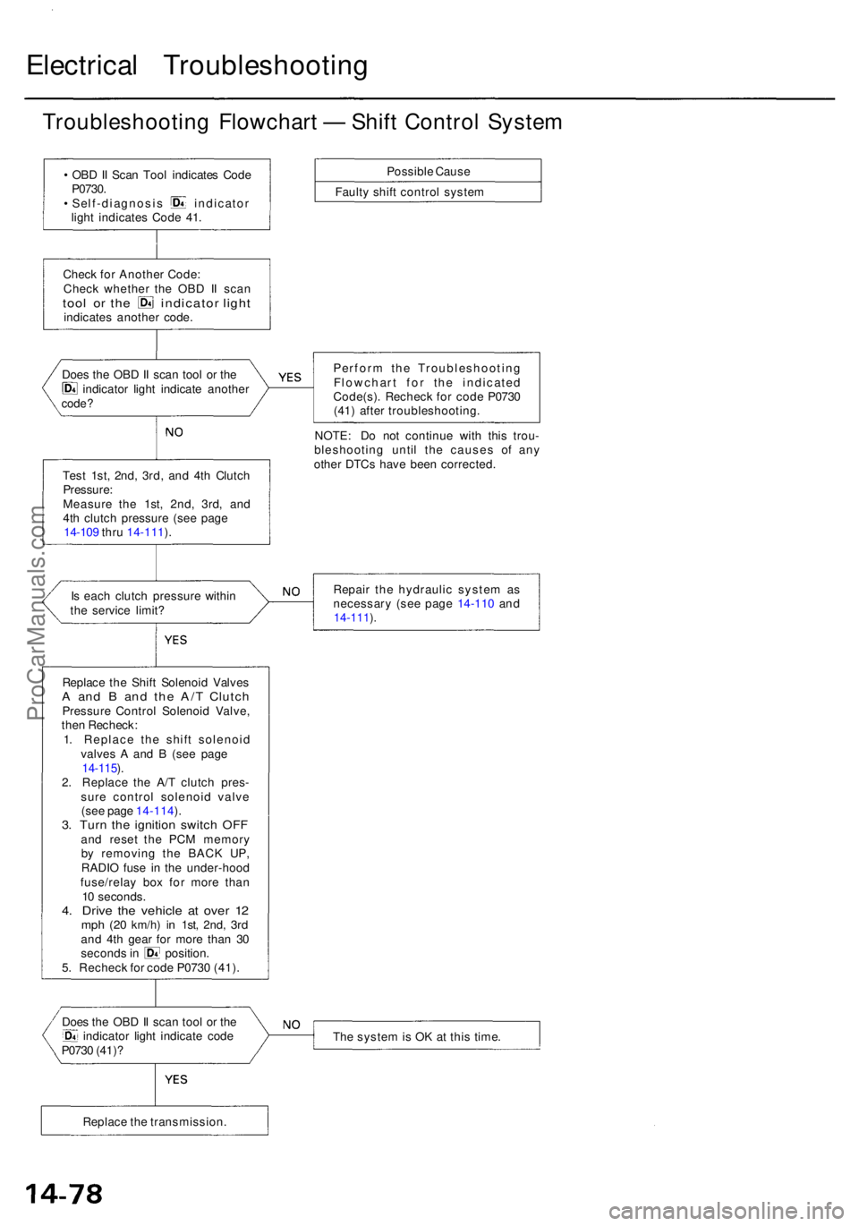
Electrical Troubleshootin g
Troubleshooting Flowchar t — Shif t Contro l Syste m
• OB D II Sca n Too l indicate s Cod eP0730 .• Self-diagnosi s indicato r
ligh t indicate s Cod e 41 .
Chec k fo r Anothe r Code :
Chec k whethe r th e OB D I I sca n
tool o r th e indicato r ligh tindicate s anothe r code .
Doe s th e OB D II sca n too l o r th e
indicato r ligh t indicat e anothe rcode?
Test 1st , 2nd , 3rd , an d 4t h Clutc h
Pressure :
Measur e th e 1st , 2nd , 3rd , an d
4t h clutc h pressur e (se e pag e
14-10 9 thr u 14-111 ).
I s eac h clutc h pressur e within
th e servic e limit ?
Replac e th e Shif t Solenoi d Valve s
A an d B an d th e A/ T Clutc hPressur e Contro l Solenoi d Valve ,
the n Recheck :
1 . Replac e th e shif t solenoi d
valve s A an d B (se e pag e
14-115 ).2 . Replac e th e A/ T clutc h pres -
sur e contro l solenoi d valv e
(se e pag e 14-114 ).
3 . Tur n th e ignitio n switc h OF Fand rese t th e PC M memor y
b y removin g th e BAC K UP ,
RADI O fus e i n th e under-hoo d
fuse/rela y bo x fo r mor e tha n
1 0 seconds .
4. Driv e th e vehicl e a t ove r 1 2mp h (2 0 km/h ) in 1st , 2nd , 3rdand 4t h gea r fo r mor e tha n 3 0second s in position .
5 . Rechec k fo r cod e P073 0 (41) .
Doe s th e OB D II sca n too l o r th e
indicato r ligh t indicat e cod e
P073 0 (41) ? Possibl
e Caus e
Fault y shif t contro l syste m
Perfor m th e Troubleshootin g
Flowchar t fo r th e indicate d
Code(s) . Rechec k fo r cod e P073 0
(41 ) afte r troubleshooting .
NOTE : D o no t continu e wit h thi s trou -
bleshootin g unti l th e cause s o f an y
othe r DTC s hav e bee n corrected .
Repai r th e hydrauli c syste m a s
necessar y (se e pag e 14-11 0 an d
14-111 ).
Th e syste m is O K a t thi s time .
Replac e th e transmission .
ProCarManuals.com
Page 786 of 1954
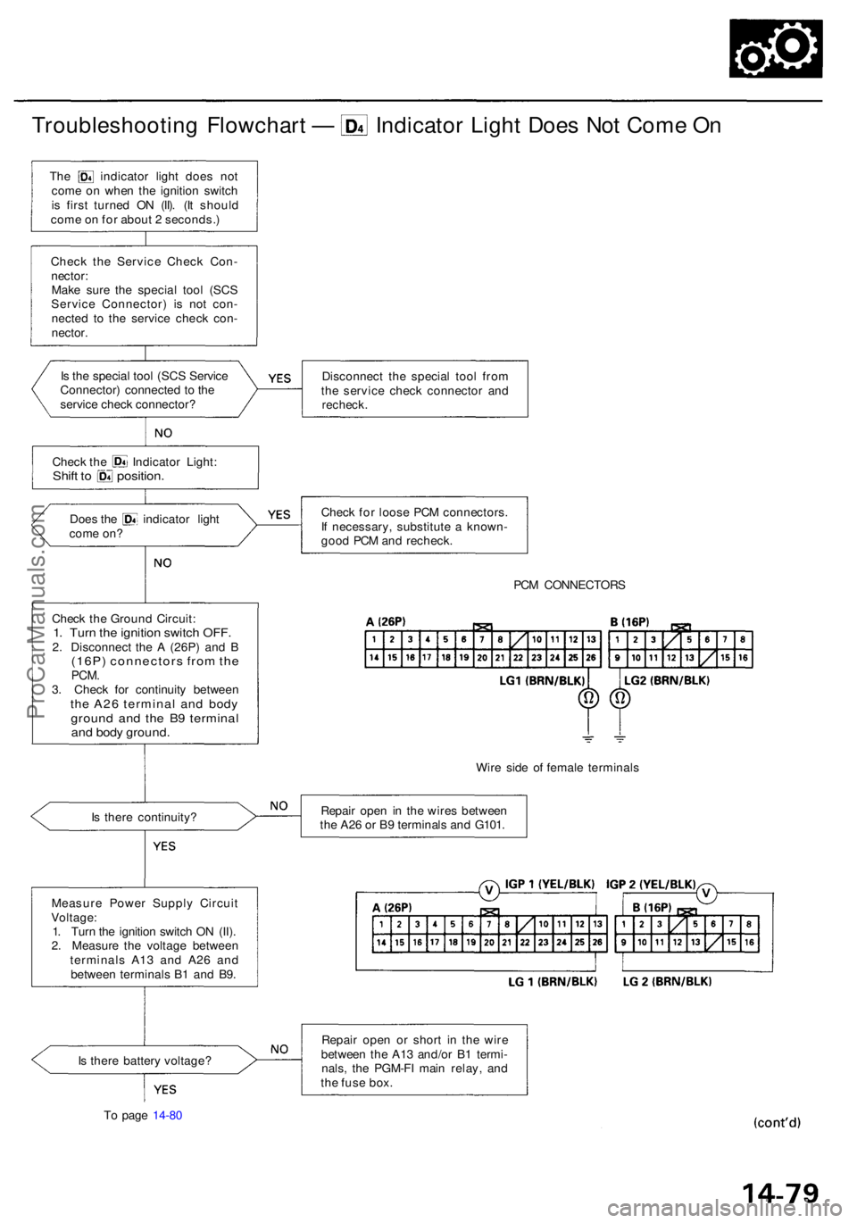
Troubleshooting Flowchar t — Indicato r Ligh t Doe s No t Com e O n
Is th e specia l too l (SC S Servic e
Connector ) connecte d t o th e
servic e chec k connector ?
Check th e Indicato r Light :Shift t o position .
Does th e indicato r ligh t
com e on ?
Chec k th e Groun d Circuit :
1. Tur n th e ignitio n switc h OFF .2. Disconnec t th e A (26P ) an d B(16P ) connector s fro m th ePCM .3. Chec k fo r continuit y betwee nthe A2 6 termina l an d bod ygroun d an d th e B 9 termina land bod y ground .
Is ther e continuity ?
Measur e Powe r Suppl y Circui t
Voltage :
1 . Tur n th e ignitio n switc h O N (II) .
2 . Measur e th e voltag e betwee n
terminal s A1 3 an d A2 6 an d
betwee n terminal s B 1 an d B9 .
I s ther e batter y voltage ?
T o pag e 14-8 0 Disconnec
t th e specia l too l fro m
th e servic e chec k connecto r an d
recheck .
Check fo r loos e PC M connectors .
I f necessary , substitut e a known -
goo d PC M an d recheck .
PCM CONNECTOR S
Wir e sid e o f femal e terminal s
Repai r ope n i n th e wire s betwee n
th e A2 6 o r B 9 terminal s an d G101 .
Repai r ope n o r shor t i n th e wir e
betwee n th e A1 3 and/o r B 1 termi -
nals , th e PGM-F I mai n relay , an d
th e fus e box .
The indicato r ligh t doe s no t
com e o n whe n th e ignitio n switc h
i s firs t turne d O N (II) . (I t shoul d
com e o n fo r abou t 2 seconds. )
Chec k th e Servic e Chec k Con -
nector :
Mak e sur e th e specia l too l (SC S
Servic e Connector ) i s no t con -
necte d t o th e servic e chec k con -
nector .
ProCarManuals.com
Page 787 of 1954
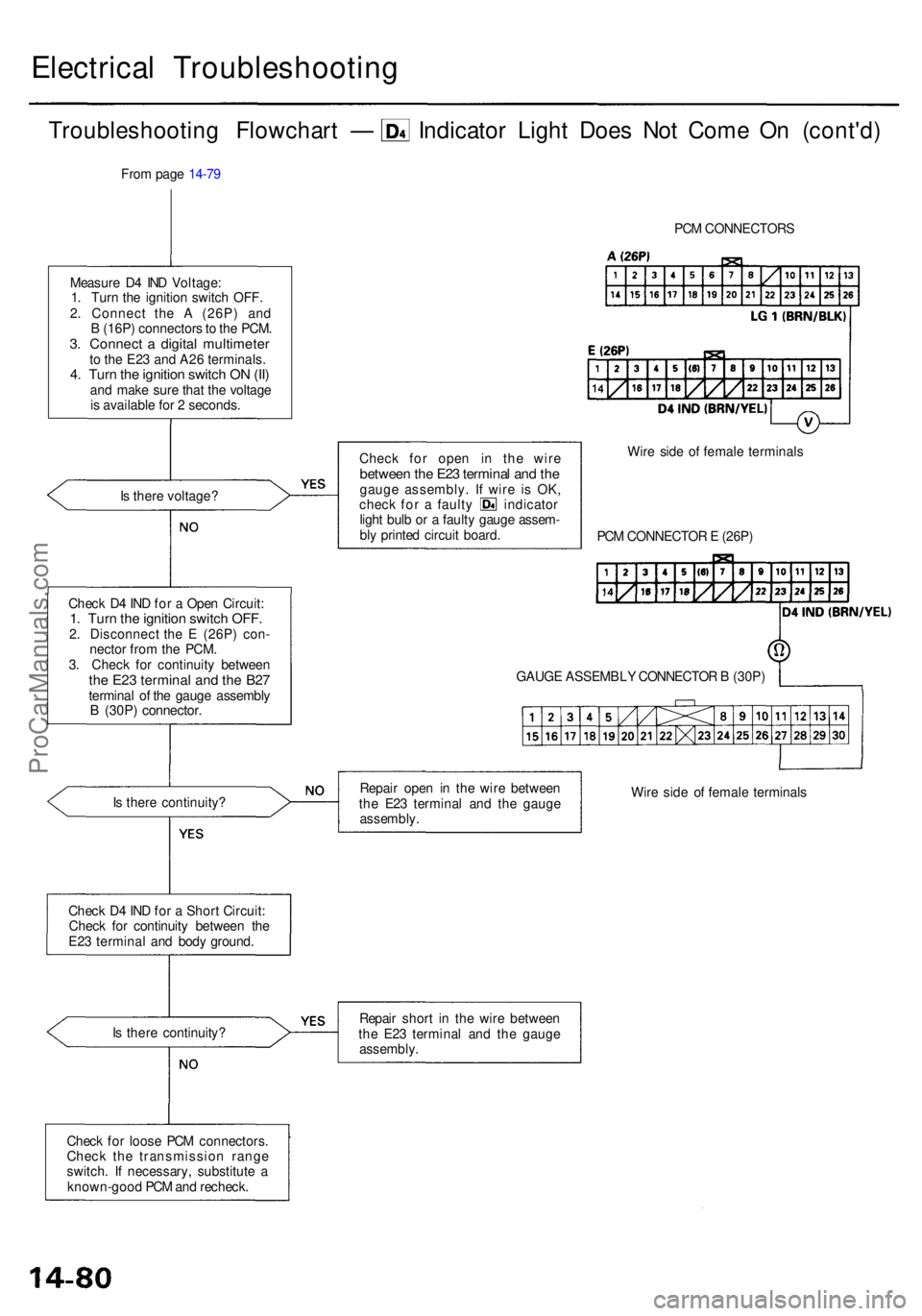
Electrical Troubleshootin g
Troubleshooting Flowchar t — Indicato r Ligh t Doe s No t Com e O n (cont'd )
Measure D 4 IN D Voltage :
1 . Tur n th e ignitio n switc h OFF .
2 . Connec t th e A (26P ) an d
B (16P ) connector s to th e PCM .
3. Connec t a digita l multimete rto th e E2 3 an d A2 6 terminals .4. Tur n th e ignitio n switc h O N (II )an d mak e sur e tha t th e voltag e
i s availabl e fo r 2 seconds .
I s ther e voltage ?
Chec k D 4 IN D fo r a Ope n Circuit :
1. Tur n th e ignitio n switc h OFF .2. Disconnec t th e E (26P ) con -
necto r fro m th e PCM .
3 . Chec k fo r continuit y betwee n
the E2 3 termina l an d th e B2 7termina l o f th e gaug e assembl yB (30P ) connector .
Is ther e continuity ?
Chec k D 4 IN D fo r a Shor t Circuit :
Chec k fo r continuit y betwee n th e
E2 3 termina l an d bod y ground .
I s ther e continuity ? PC
M CONNECTOR S
Chec k fo r ope n i n th e wir e
betwee n th e E2 3 termina l an d th egaug e assembly . I f wir e i s OK ,chec k fo r a fault y indicato r
ligh t bul b o r a fault y gaug e assem -
bl y printe d circui t board . Wir
e sid e o f femal e terminal s
PC M CONNECTO R E (26P )
GAUG E ASSEMBL Y CONNECTO R B (30P )
Repai r shor t i n th e wir e betwee n
th e E2 3 termina l an d th e gaug e
assembly .
Fro
m pag e 14-7 9
Chec k fo r loos e PC M connectors .
Chec k th e transmissio n rang e
switch . I f necessary , substitut e a
known-goo d PC M an d recheck . Wir
e sid e o f femal e terminal s
Repai
r ope n i n th e wir e betwee n
th e E2 3 termina l an d th e gaug e
assembly .
ProCarManuals.com
Page 788 of 1954
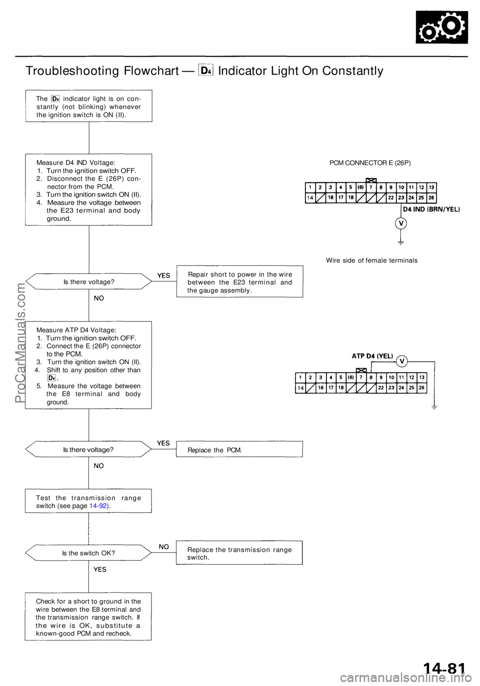
Troubleshooting Flowchar t — Indicato r Ligh t O n Constantl y
The indicato r ligh t i s o n con -
stantl y (no t blinking ) wheneve r
th e ignitio n switc h is O N (II) .
Measur e D 4 IN D Voltage :
1. Tur n th e ignitio n switc h OFF .2. Disconnec t th e E (26P ) con -
necto r fro m th e PCM .
3. Tur n th e ignitio n switc h O N (II) .4. Measur e th e voltag e betwee nthe E2 3 termina l an d bod yground .
Is ther e voltage ?
Measur e AT P D 4 Voltage :
1. Tur n th e ignitio n switc h OFF .2. Connec t th e E (26P ) connecto rto th e PCM .3. Tur n th e ignitio n switc h O N (II) .4. Shif t t o an y positio n othe r tha n
5 . Measur e th e voltag e betwee n
th e E 8 termina l an d bod y
ground .
Is ther e voltage ?
Test th e transmissio n rang e
switc h (se e pag e 14-92 ).
I s th e switc h OK ?
Chec k fo r a shor t t o groun d in th e
wir e betwee n th e E 8 termina l an d
th e transmissio n rang e switch . I f
th e wir e i s OK , substitut e aknown-goo d PC M an d recheck . PC
M CONNECTO R E (26P )
Wir e sid e o f femal e terminal s
Repai r shor t t o powe r i n th e wir e
betwee n th e E2 3 termina l an d
th e gaug e assembly .
Replac e th e PCM .
Replac e th e transmissio n rang e
switch .
ProCarManuals.com
Page 789 of 1954
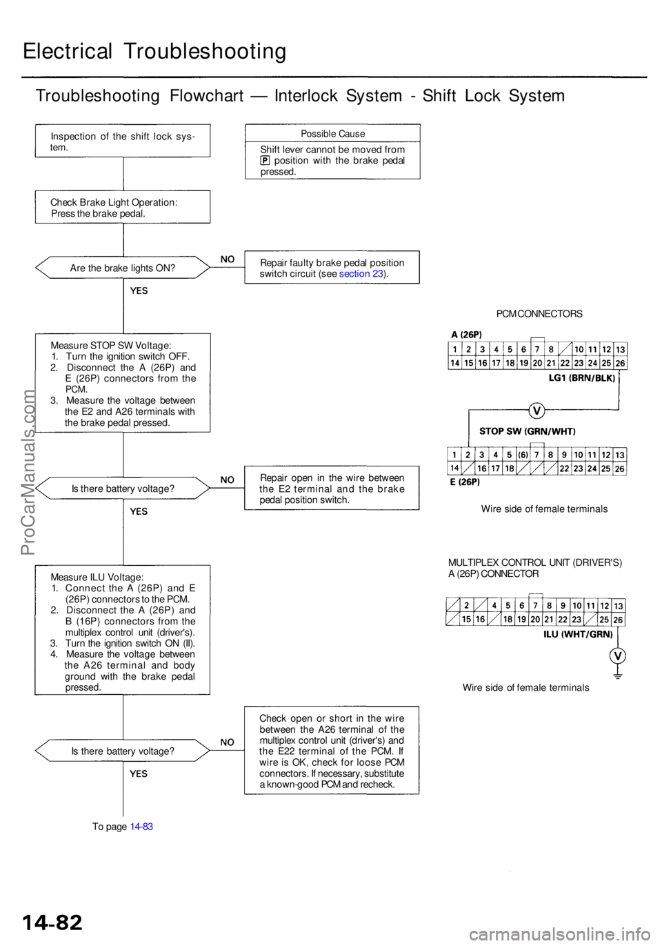
Electrical Troubleshootin g
Troubleshooting Flowchar t — Interloc k Syste m - Shif t Loc k Syste m
Inspectio n o f th e shif t loc k sys -tem.
Chec k Brak e Ligh t Operation :
Pres s th e brak e pedal .
Ar e th e brak e light s ON ?
Measur e STO P S W Voltage :
1 . Tur n th e ignitio n switc h OFF .
2 . Disconnec t th e A (26P ) an d
E (26P ) connector s fro m th e
PCM .3. Measur e th e voltag e betwee n
th e E 2 an d A2 6 terminal s wit h
th e brak e peda l pressed .
I s ther e batter y voltage ?
I s ther e batter y voltage ?
T o pag e 14-8 3
Possibl e Caus e
Shift leve r canno t b e move d fro mpositio n wit h th e brak e peda lpressed .
Repair fault y brak e peda l positio n
switc h circui t (se e sectio n 23 ).
Repai r ope n i n th e wir e betwee n
th e E 2 termina l an d the brak e
peda l positio n switch .
Chec k ope n o r shor t i n th e wir e
betwee n th e A2 6 termina l o f th e
multiple x contro l uni t (driver's ) an d
th e E2 2 termina l o f th e PCM . I f
wir e i s OK , chec k fo r loos e PC M
connectors . I f necessary , substitut e
a known-goo d PC M an d recheck . PC
M CONNECTOR S
Wir e sid e o f femal e terminal s
MULTIPLE X CONTRO L UNI T (DRIVER'S )
A (26P ) CONNECTO R
Wir e sid e o f femal e terminal s
Measur
e IL U Voltage :
1 . Connec t th e A (26P ) an d E
(26P ) connector s to th e PCM .
2 . Disconnec t th e A (26P ) an d
B (16P ) connector s fro m th e
multiple x contro l uni t (driver's) .
3 . Tur n th e ignitio n switc h O N (II) .
4 . Measur e th e voltag e betwee n
th e A2 6 termina l an d bod y
groun d wit h th e brak e peda l
pressed .
ProCarManuals.com
Page 790 of 1954
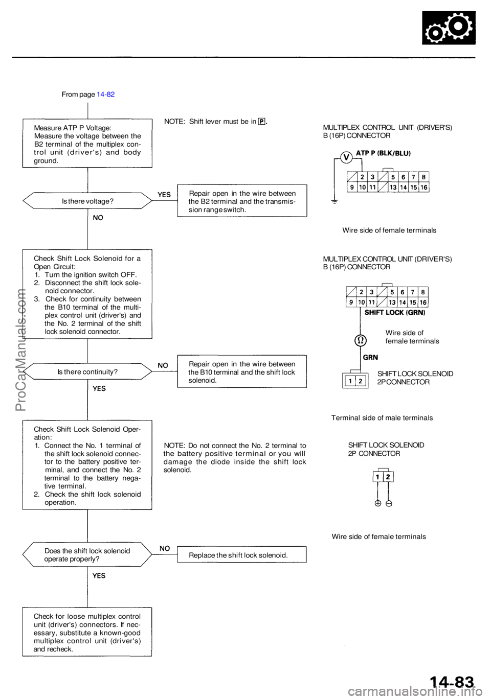
From pag e 14-8 2
Measur e AT P P Voltage :
Measur e th e voltag e betwee n th e
B 2 termina l o f th e multiple x con -
trol uni t (driver's ) an d bod yground .
NOTE: Shif t leve r mus t b e in
MULTIPLEX CONTRO L UNI T (DRIVER'S )
B (16P ) CONNECTO R
I s ther e voltage ?
Chec k Shif t Loc k Solenoi d fo r a
Ope n Circuit :
1 . Tur n th e ignitio n switc h OFF .
2 . Disconnec t th e shif t loc k sole -
noi d connector .
3 . Chec k fo r continuit y betwee n
th e B1 0 termina l o f th e multi -
ple x contro l uni t (driver's ) an d
th e No . 2 termina l o f th e shif t
loc k solenoi d connector .
I s ther e continuity ?
Doe s th e shif t loc k solenoi d
operat e properly ?
Chec k fo r loos e multiple x contro l
uni t (driver's ) connectors . I f nec -
essary , substitut e a known-goo d
multiple x contro l uni t (driver's )
an d recheck . Repai
r ope n in th e wir e betwee n
th e B 2 termina l an d th e transmis -
sio n rang e switch .
Wire sid e o f femal e terminal s
MULTIPLE X CONTRO L UNI T (DRIVER'S )
B (16P ) CONNECTO R
Wir e sid e o f
femal e terminal s
Repai r ope n in th e wir e betwee n
th e B1 0 termina l an d th e shif t loc k
solenoid .
NOTE: D o no t connec t th e No . 2 termina l t oth e batter y positiv e termina l o r yo u wil ldamag e th e diod e insid e th e shif t loc k
solenoid . SHIF
T LOC K SOLENOI D
2 P CONNECTO R
Termina l sid e o f mal e terminal s
SHIF T LOC K SOLENOI D2P CONNECTO R
Wire sid e o f femal e terminal s
Replac e th e shif t loc k solenoid .
Chec
k Shif t Loc k Solenoi d Oper -
ation:1. Connec t th e No . 1 termina l o f
th e shif t loc k solenoi d connec -
to r t o th e batter y positiv e ter -
minal , an d connec t th e No . 2
termina l t o th e batter y nega -
tiv e terminal .
2 . Chec k th e shif t loc k solenoid
operation .
ProCarManuals.com