ACURA TL 1995 Service Repair Manual
Manufacturer: ACURA, Model Year: 1995, Model line: TL, Model: ACURA TL 1995Pages: 1771, PDF Size: 62.49 MB
Page 971 of 1771
Description
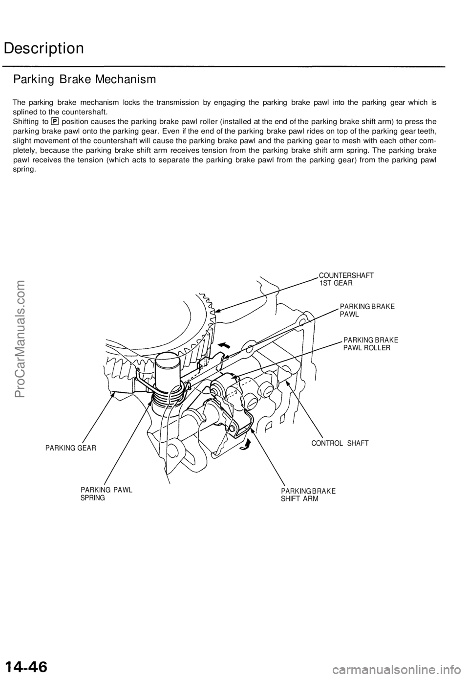
The parking brake mechanism locks the transmission by engaging the parking brake pawl into the parking gear which is
splined to the countershaft.
Shifting to position causes the parking brake pawl roller (installed at the end of the parking brake shift arm) to press the
parking brake pawl onto the parking gear. Even if the end of the parking brake pawl rides on top of the parking gear teeth,
slight movement of the countershaft will cause the parking brake pawl and the parking gear to mesh with each other com-
pletely, because the parking brake shift arm receives tension from the parking brake shift arm spring. The parking brake
pawl receives the tension (which acts to separate the parking brake pawl from the parking gear) from the parking pawl
spring.
PARKING GEAR
COUNTERSHAFT
1ST GEAR
PARKING BRAKE
PAWL
PARKING BRAKE
PAWL ROLLER
CONTROL SHAFT
PARKING PAWL
SPRING
PARKING BRAKE
SHIFT ARM
Parking Brake MechanismProCarManuals.com
Page 972 of 1771
Component Locations
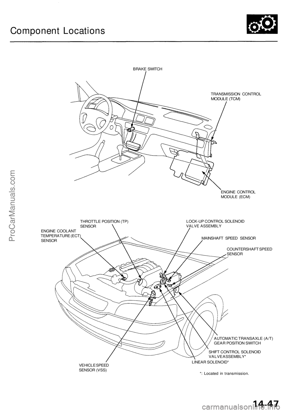
BRAKE SWITCH
TRANSMISSION CONTROL
MODULE (TCM)
ENGINE CONTROL
MODULE (ECM)
THROTTLE POSITION (TP)
SENSOR
ENGINE COOLANT
TEMPERATURE (ECT)
SENSOR
LOCK-UP CONTROL SOLENOID
VALVE ASSEMBLY
MAINSHAFT SPEED SENSOR
COUNTERSHAFT SPEED
SENSOR
VEHICLE SPEED
SENSOR (VSS)
AUTOMATIC TRANSAXLE (A/T)
GEAR POSITION SWITCH
SHIFT CONTROL SOLENOID
VALVE ASSEMBLY*
LINEAR SOLENOID*
*: Located in transmission.ProCarManuals.com
Page 973 of 1771
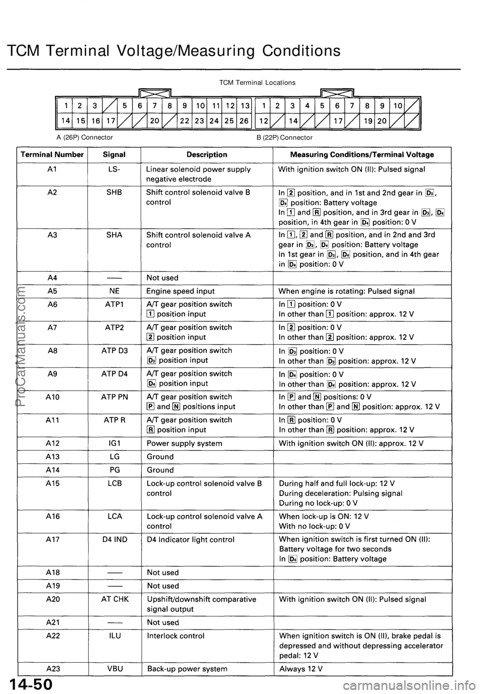
TCM Terminal Voltage/Measuring Conditions
TCM Terminal Locations
A (26P) Connector
B (22P) ConnectorProCarManuals.com
Page 974 of 1771
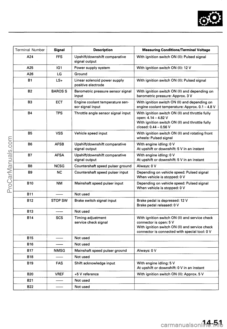
Terminal NumberProCarManuals.com
Page 975 of 1771
Troubleshooting Procedures
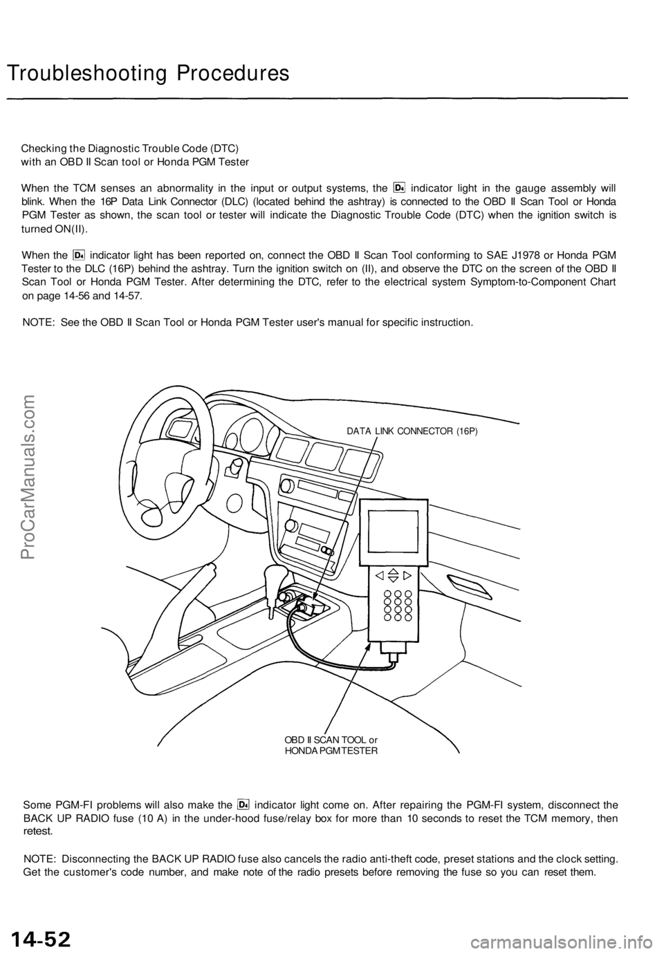
Checking the Diagnostic Trouble Code (DTC)
with an OBD II Scan tool or Honda PGM Tester
When the TCM senses an abnormality in the input or output systems, the indicator light in the gauge assembly will
blink. When the 16P Data Link Connector (DLC) (located behind the ashtray) is connected to the OBD II Scan Tool or Honda
PGM Tester as shown, the scan tool or tester will indicate the Diagnostic Trouble Code (DTC) when the ignition switch is
turned ON(II).
When the indicator light has been reported on, connect the OBD II Scan Tool conforming to SAE J1978 or Honda PGM
Tester to the DLC (16P) behind the ashtray. Turn the ignition switch on (II), and observe the DTC on the screen of the OBD II
Scan Tool or Honda PGM Tester. After determining the DTC, refer to the electrical system Symptom-to-Component Chart
on page 14-56 and 14-57.
NOTE: See the OBD II Scan Tool or Honda PGM Tester user's manual for specific instruction.
OBD II SCAN TOOL or
HONDA PGM TESTER
Some PGM-FI problems will also make the indicator light come on. After repairing the PGM-FI system, disconnect the
BACK UP RADIO fuse (10 A) in the under-hood fuse/relay box for more than 10 seconds to reset the TCM memory, then
retest.
NOTE: Disconnecting the BACK UP RADIO fuse also cancels the radio anti-theft code, preset stations and the clock setting.
Get the customer's code number, and make note of the radio presets before removing the fuse so you can reset them.
DATA LINK CONNECTOR (16P)ProCarManuals.com
Page 976 of 1771
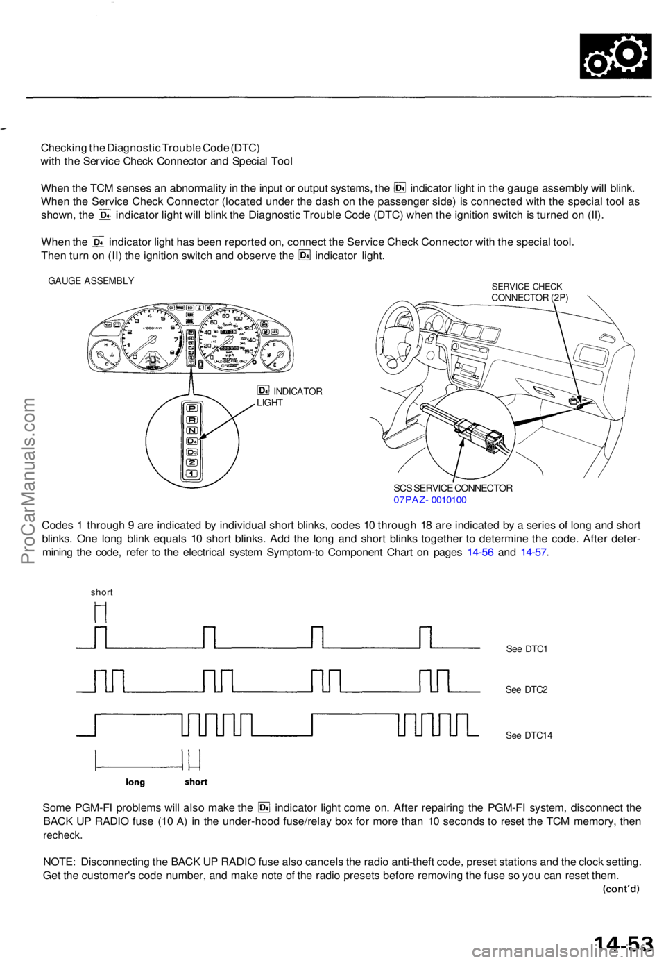
Checking th e Diagnosti c Troubl e Cod e (DTC )
wit h th e Servic e Chec k Connecto r an d Specia l Too l
Whe n th e TC M sense s a n abnormalit y in th e inpu t o r outpu t systems , th e indicato r ligh t i n th e gaug e assembl y wil l blink .
Whe n th e Servic e Chec k Connecto r (locate d unde r th e das h o n th e passenge r side ) i s connecte d wit h th e specia l too l a s
shown , th e indicato r ligh t wil l blin k th e Diagnosti c Troubl e Cod e (DTC ) whe n th e ignitio n switc h is turne d o n (II) .
Whe n th e indicato r ligh t ha s bee n reporte d on , connec t th e Servic e Chec k Connecto r wit h th e specia l tool .
Then tur n o n (II ) th e ignitio n switc h an d observ e th e indicato r light .
GAUG E ASSEMBL YSERVICE CHEC KCONNECTO R (2P )
INDICATO RLIGHT
SCS SERVIC E CONNECTO R07PAZ- 001010 0
Codes 1 throug h 9 ar e indicate d b y individua l shor t blinks , code s 1 0 throug h 1 8 ar e indicate d b y a serie s o f lon g an d shor t
blinks . On e lon g blin k equal s 1 0 shor t blinks . Ad d th e lon g an d shor t blink s togethe r t o determin e th e code . Afte r deter -
minin g th e code , refe r t o th e electrica l syste m Symptom-t o Componen t Char t o n page s 14-5 6 an d 14-57 .
short
Some PGM-F I problem s wil l als o mak e th e indicato r ligh t com e on . Afte r repairin g th e PGM-F I system , disconnec t th e
BAC K U P RADI O fus e (1 0 A ) i n th e under-hoo d fuse/rela y bo x fo r mor e tha n 1 0 second s t o rese t th e TC M memory , the n
recheck .
NOTE: Disconnectin g th e BAC K U P RADI O fus e als o cancel s th e radi o anti-theft code, prese t station s an d th e cloc k setting .
Ge t th e customer' s cod e number , an d mak e not e o f th e radi o preset s befor e removin g th e fus e s o yo u ca n rese t them .
See DTC 1
See DTC 2
See DTC1 4
ProCarManuals.com
Page 977 of 1771
Troubleshooting Procedure s
(cont'd)
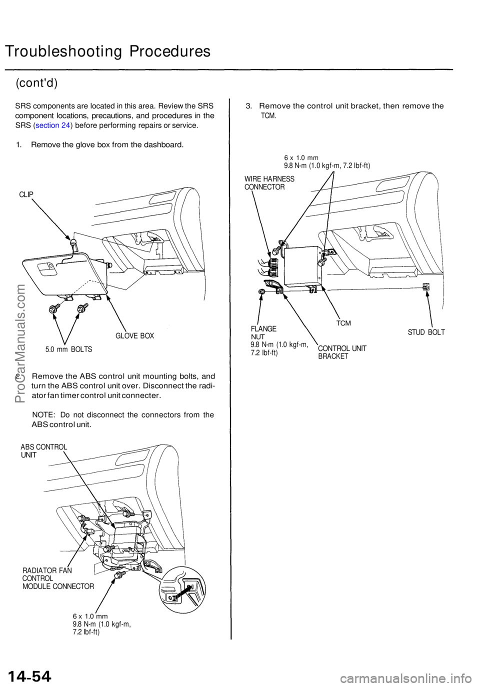
SRS component s ar e locate d in thi s area . Revie w th e SR S
componen t locations , precautions , an d procedure s in th e
SR S (sectio n 24 ) befor e performin g repair s o r service .
1. Remov e th e glov e bo x fro m th e dashboard .
CLIP
GLOV E BO X
5. 0 m m BOLT S
2.Remov e th e AB S contro l uni t mountin g bolts , an d
tur n th e AB S contro l uni t over . Disconnec t th e radi -
ato r fa n time r contro l uni t connecter .
NOTE: D o no t disconnec t th e connector s fro m th e
AB S contro l unit .
ABS CONTRO LUNIT
RADIATO R FA N
CONTRO L
MODULE CONNECTO R
6 x 1. 0 m m9.8 N- m (1. 0 kgf-m ,
7. 2 Ibf-ft )
3. Remov e th e contro l uni t bracket , the n remov e th e
TCM .
6 x 1. 0 m m9.8 N- m (1. 0 kgf-m , 7. 2 Ibf-ft )
WIR E HARNES S
CONNECTO R
STUD BOL T
CONTRO L UNI TBRACKE T
TCMFLANG ENUT9.8 N- m (1. 0 kgf-m ,
7. 2 Ibf-ft )
ProCarManuals.com
Page 978 of 1771
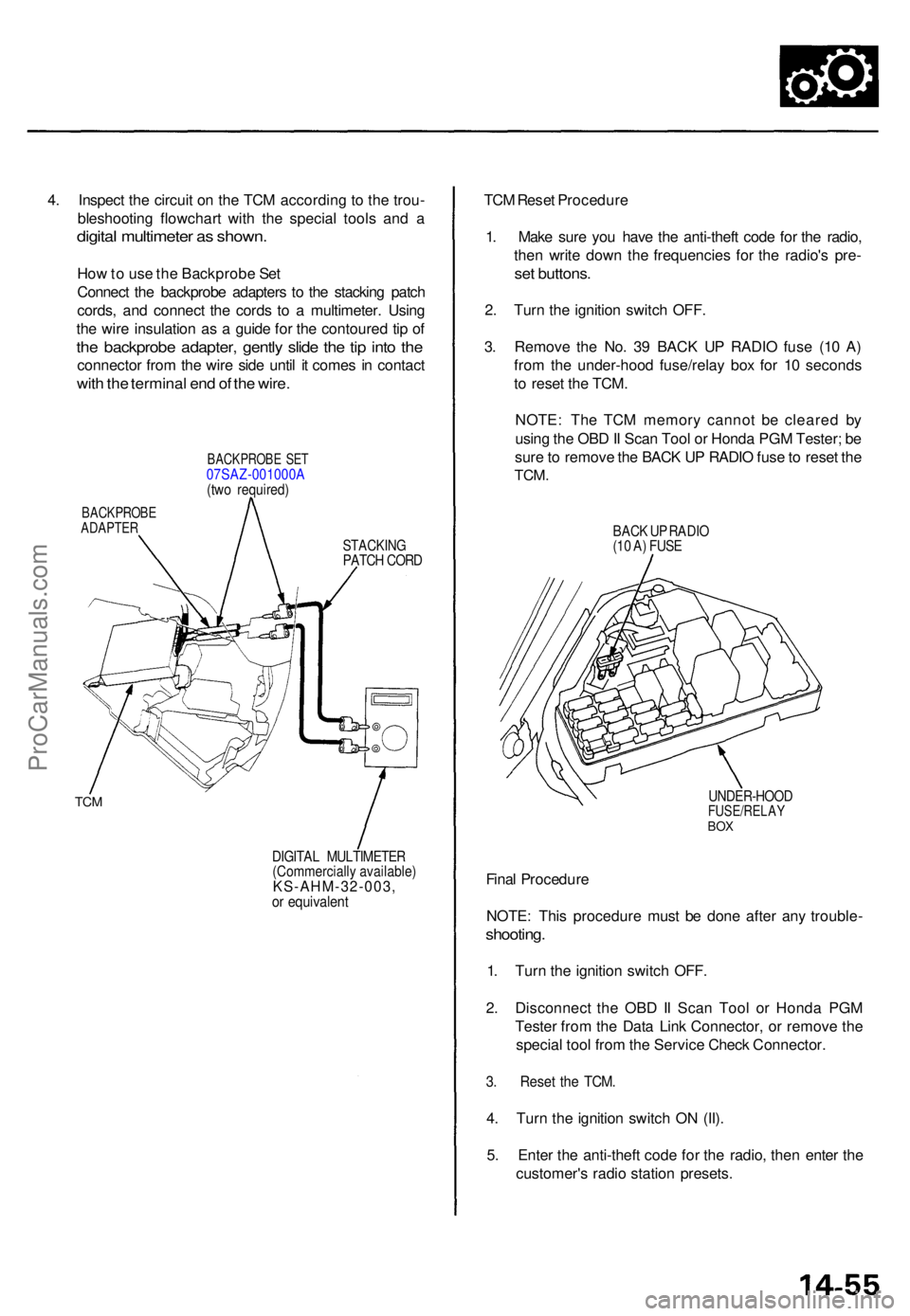
4. Inspec t th e circui t o n th e TC M accordin g t o th e trou -
bleshootin g flowchar t wit h th e specia l tool s an d a
digita l multimete r a s shown .
How to us e th e Backprob e Se t
Connec t th e backprob e adapter s t o th e stackin g patc h
cords , an d connec t th e cord s t o a multimeter . Usin g
th e wir e insulatio n a s a guid e fo r th e contoure d ti p o f
the backprob e adapter , gentl y slid e th e ti p int o th e
connecto r fro m th e wir e sid e unti l i t come s i n contac t
with th e termina l en d o f th e wire .
BACKPROB E SE T07SAZ-001000 A
(tw o required )
BACKPROB EADAPTER
STACKIN GPATCH COR D
TCM
DIGITA L MULTIMETE R
(Commerciall y available )
KS-AHM-32-003 ,or equivalen t
TCM Rese t Procedur e
1 . Mak e sur e yo u hav e th e anti-thef t cod e fo r th e radio ,
the n writ e dow n th e frequencie s fo r th e radio' s pre -
set buttons .
2. Tur n th e ignitio n switc h OFF .
3 . Remov e th e No . 3 9 BAC K U P RADI O fus e (1 0 A )
fro m th e under-hoo d fuse/rela y bo x fo r 1 0 second s
t o rese t th e TCM .
NOTE : Th e TC M memor y canno t b e cleare d b y
usin g th e OB D II Sca n Too l o r Hond a PG M Tester ; b e
sur e to remov e th e BAC K U P RADI O fus e to rese t th e
TCM .
BACK U P RADI O
(1 0 A ) FUS E
UNDER-HOO D
FUSE/RELAYBOX
Fina l Procedur e
NOTE : Thi s procedur e mus t b e don e afte r an y trouble -
shooting.
1. Tur n th e ignitio n switc h OFF .
2 . Disconnec t th e OB D II Sca n Too l o r Hond a PG M
Teste r fro m th e Dat a Lin k Connector , o r remov e th e
specia l too l fro m th e Servic e Chec k Connector .
3. Rese t th e TCM .
4. Tur n th e ignitio n switc h O N (II) .
5 . Ente r th e anti-thef t cod e fo r th e radio , the n ente r th e
customer' s radi o statio n presets .
ProCarManuals.com
Page 979 of 1771
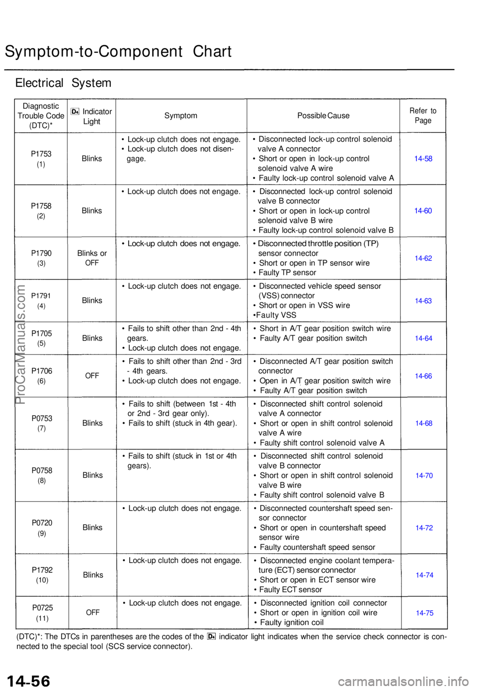
Symptom-to-Component Char t
Electrica l Syste m
Diagnosti c
Troubl e Cod e
(DTC) *
P1753
(1)
P175 8
(2)
P179 0
(3)
P179 1
(4)
P170 5
(5)
P170 6
(6)
P075 3
(7)
P075 8
(8)
P072 0
(9)
P179 2
(10)
P072 5
(11)
Indicato r
Light
Blink s
Blink s
Blinks o r
OF F
Blink s
Blink s
OFF
Blink s
Blink s
Blinks
Blink s
OFF
Sympto m
• Lock-u p clutc h doe s no t engage .
• Lock-u p clutc h doe s no t disen -
gage.
• Lock-u p clutc h doe s no t engage .
• Lock-u p clutc h doe s no t engage .
• Lock-u p clutc h doe s no t engage .
• Fail s t o shif t othe r tha n 2n d - 4t h
gears .
• Lock-u p clutc h doe s no t engage .
• Fail s t o shif t othe r tha n 2n d - 3r d
- 4t h gears .
• Lock-u p clutc h doe s no t engage .
• Fail s t o shif t (betwee n 1s t - 4t h
o r 2n d - 3r d gea r only) .
• Fail s t o shif t (stuc k in 4t h gear) .
• Fail s t o shif t (stuc k i n 1s t o r 4t h
gears) .
• Lock-u p clutc h doe s no t engage .
• Lock-u p clutc h doe s no t engage .
• Lock-u p clutc h doe s no t engage . Possibl
e Caus e
• Disconnecte d lock-u p contro l solenoi d
valv e A connecto r
• Shor t o r ope n i n lock-u p contro l
solenoi d valv e A wir e
• Fault y lock-u p contro l solenoi d valv e A
• Disconnecte d lock-u p contro l solenoi d
valv e B connecto r
• Shor t o r ope n i n lock-u p contro l
solenoi d valv e B wir e
• Fault y lock-u p contro l solenoi d valv e B
• Disconnecte d throttl e positio n (TP )
senso r connecto r
• Shor t o r ope n in T P senso r wir e
• Fault y T P senso r
• Disconnecte d vehicl e spee d senso r
(VSS ) connecto r
• Shor t o r ope n i n VS S wir e
•Fault y VS S
• Shor t i n A/ T gea r positio n switc h wir e
• Fault y A/ T gea r positio n switc h
• Disconnecte d A/ T gea r positio n switc h
connecto r
• Ope n i n A/ T gea r positio n switc h wir e
• Fault y A/ T gea r positio n switc h
• Disconnecte d shif t contro l solenoi d
valv e A connecto r
• Shor t o r ope n i n shif t contro l solenoi d
valv e A wir e
• Fault y shif t contro l solenoi d valv e A
• Disconnecte d shif t contro l solenoi d
valv e B connecto r
• Shor t o r ope n i n shif t contro l solenoi d
valv e B wir e
• Fault y shif t contro l solenoi d valv e B
• Disconnecte d countershaf t spee d sen -
so r connecto r
• Shor t o r ope n i n countershaf t spee d
senso r wir e
• Fault y countershaf t spee d senso r
• Disconnecte d engin e coolan t tempera -
ture (ECT ) senso r connecto r
• Shor t o r ope n in EC T senso r wir e
• Fault y EC T senso r
• Disconnecte d ignitio n coi l connecto r
• Shor t o r ope n i n ignitio n coi l wir e
• Fault y ignitio n coi l
Refe r t o
Pag e
14-5 8
14-6 0
14-6 2
14-6 3
14-6 4
14-6 6
14-6 8
14-7 0
14-7 2
14-7 4
14-7 5
(DTC)* : Th e DTC s i n parenthese s ar e th e code s o f th e indicato r ligh t indicate s whe n th e servic e chec k connecto r i s con -
necte d to th e specia l too l (SC S servic e connector) .
ProCarManuals.com
Page 980 of 1771
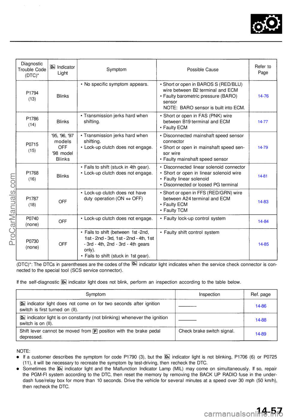
Diagnostic
Troubl e Cod e
(DTC) *
P1794
(13)
P178 6
(14)
P071 5
(15)
P176 8
(16)
P178 7
(18)
P074 0
(none )
P0730
(none )
Indicato r
Light
Blink s
Blinks
'95, '96 , '97
model s
OFF
'98 mode l
Blink s
Blinks
OFF
OF F
OFF
Sympto m
• N o specifi c sympto m appears .
• Transmissio n jerk s har d whe n
shifting .
• Transmissio n jerk s har d whe n
shifting .
• Lock-u p clutc h doe s no t engage .
• Fail s t o shif t (stuc k in 4t h gear) .
• Lock-u p clutc h doe s no t engage .
• Lock-u p clutc h doe s no t hav e
duty operatio n (O N OFF )
• Lock-u p clutc h doe s no t engage .
• Fail s t o shif t (betwee n 1s t -2nd,
1s t - 2n d - 3rd , 1st - 2nd - 4th , 1st
- 3r d - 4th , 2n d - 3r d - 4t h gear s
only) .
• Fail s t o shif t (stuc k in 1s t gear) .
Possibl e Caus e
• Shor t o r ope n in BARO S S (RED/BLU )
wir e betwee n B 2 termina l an d EC M
• Fault y barometri c pressur e (BARO )
sensor
NOTE : BAR O senso r i s buil t int o ECM .
• Shor t o r ope n in FA S (PNK ) wir e
betwee n B1 9 termina l an d EC M
• Fault y EC M
• Disconnecte d mainshaf t spee d senso r
connecto r
• Shor t o r ope n in mainshaf t spee d sen -
so r wir e
• Fault y mainshaf t spee d senso r
• Disconnecte d linea r solenoi d connecto r
• Shor t o r ope n in linea r solenoi d wir e
• Fault y linea r solenoi d
• Disconnecte d o r loose d P G termina l
• Shor t o r ope n in FF S (RED/GRN ) wir e
betwee n A2 4 termina l an d EC M
• Fault y EC M
• Fault y TC M
• Fault y lock-u p contro l syste m
• Fault y shif t contro l syste m
Refer t o
Pag e
14-7 6
14-77
14-7 9
14-8 1
14-8 3
14-8 4
14-8 5
(DTC)* : Th e DTC s i n parenthese s ar e th e code s o f th e indicato r ligh t indicate s whe n th e servic e chec k connecto r i s con -
necte d t o th e specia l too l (SC S servic e connector) .
If th e self-diagnosti c indicato r ligh t doe s no t blink , perfor m a n inspectio n accordin g t o th e tabl e below .
Sympto m
indicator ligh t doe s no t com e o n fo r tw o second s afte r ignitio n
switc h i s firs t turne d o n (II) .
indicato r ligh t i s o n constantl y (no t blinking ) wheneve r th e ignitio n
switch i s o n (II) .
Shif t leve r canno t b e move d fro m positio n wit h th e brak e peda l
depressed . Inspectio
n
Chec k brak e switc h signal . Ref
. pag e
14-86
14-8 8
14-8 9
NOTE :
If a custome r describe s th e sympto m fo r cod e P179 0 (3) , bu t th e indicato r ligh t i s no t blinking , P170 6 (6 ) o r P072 5
(11) , i t wil l b e necessar y t o recreat e th e sympto m b y test-driving , the n rechec k th e DTC .
Sometime s th e indicato r ligh t an d th e Malfunctio n Indicato r Lam p (MIL ) ma y com e o n simultaneously . I f so , repai r
th e PGM-F I syste m accordin g t o th e DTC , the n rese t th e memor y b y removin g th e BAC K U P RADI O fus e i n th e under -
das h fuse/rela y bo x fo r mor e tha n 1 0 seconds . Driv e th e vehicl e fo r severa l minute s a t a spee d ove r 3 0 mp h (5 0 km/h) ,
the n rechec k th e DTC .
ProCarManuals.com