ACURA TL 1995 Service Repair Manual
Manufacturer: ACURA, Model Year: 1995,
Model line: TL,
Model: ACURA TL 1995
Pages: 1771, PDF Size: 62.49 MB
ACURA TL 1995 Service Repair Manual
TL 1995
ACURA
ACURA
https://www.carmanualsonline.info/img/32/56993/w960_56993-0.png
ACURA TL 1995 Service Repair Manual
Trending: emergency towing, headlight aiming, diagram, power steering fluid, fuel filter, spark plugs, power steering
Page 941 of 1771
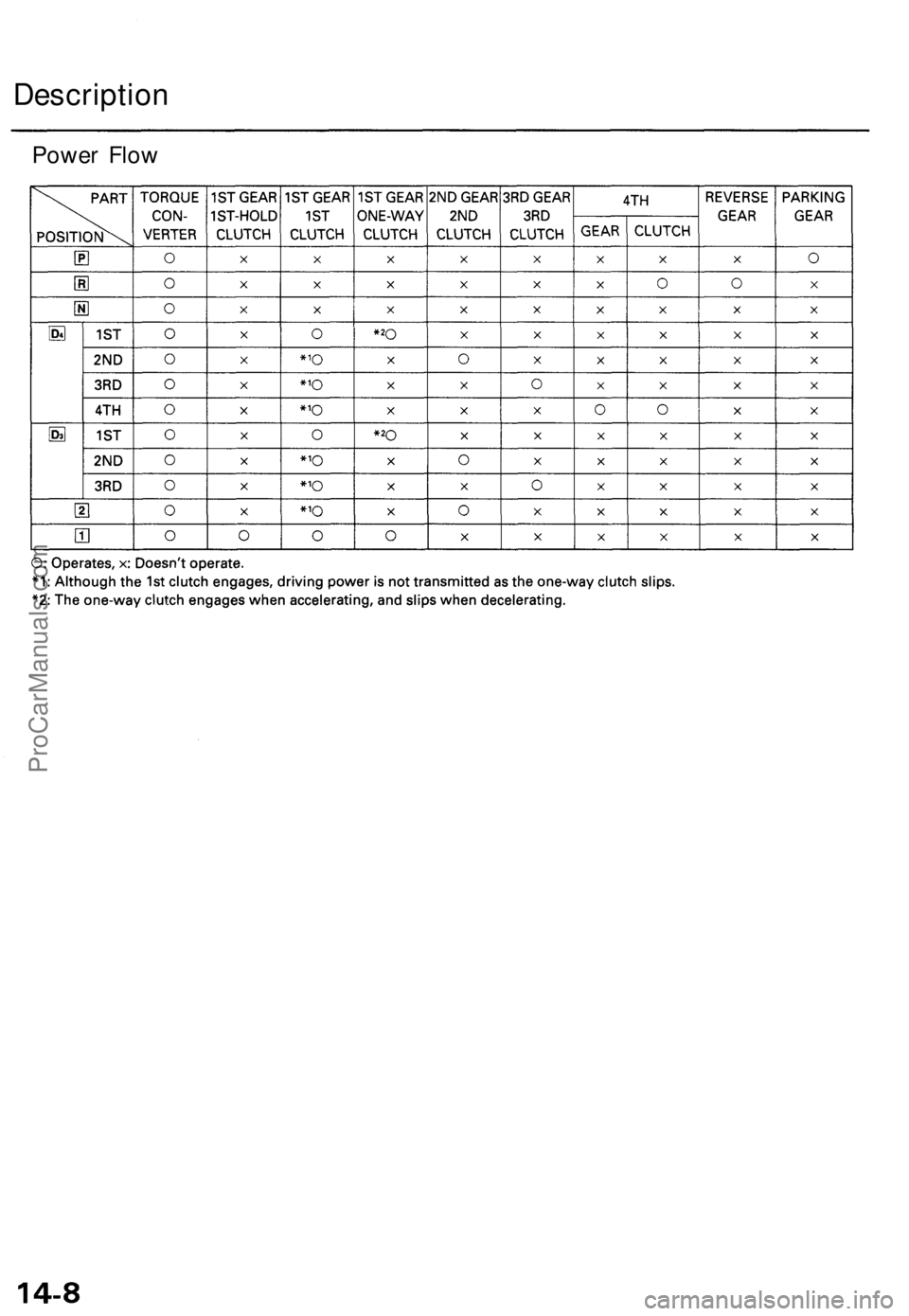
Description
Power FlowProCarManuals.com
Page 942 of 1771
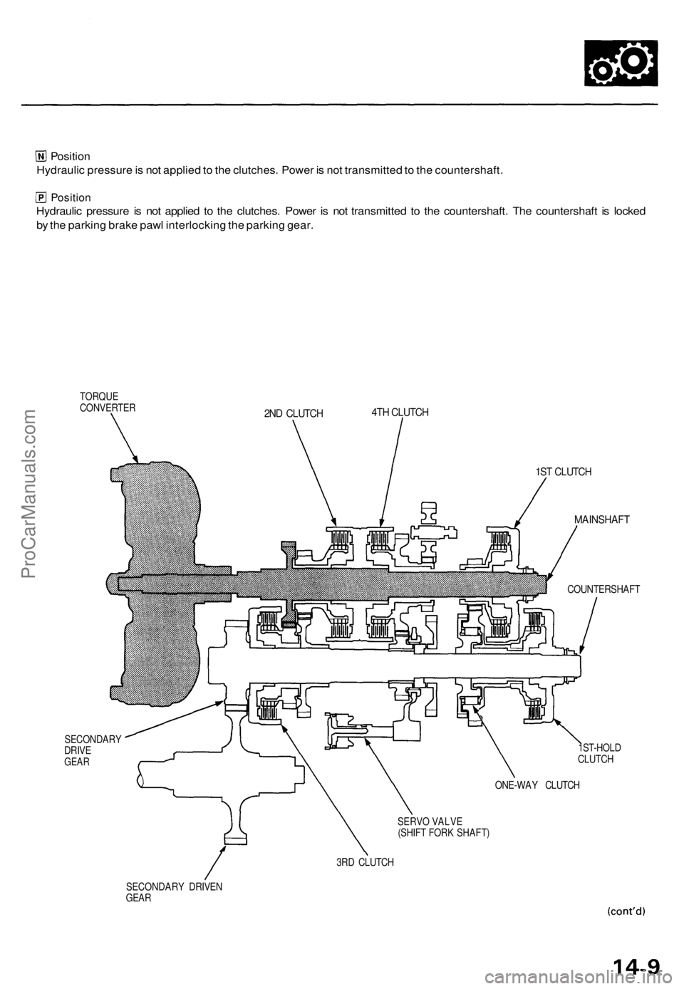
Position
Hydraulic pressure is not applied to the clutches. Power is not transmitted to the countershaft.
Position
Hydraulic pressure is not applied to the clutches. Power is not transmitted to the countershaft. The countershaft is locked
by the parking brake pawl interlocking the parking gear.
TORQUE
CONVERTER
SECONDARY
DRIVE
GEAR
2ND CLUTCH
4TH CLUTCH
1ST CLUTCH
MAINSHAFT
COUNTERSHAFT
1ST-HOLD
CLUTCH
ONE-WAY CLUTCH
SERVO VALVE
(SHIFT FORK SHAFT)
3RD CLUTCH
SECONDARY DRIVEN
GEARProCarManuals.com
Page 943 of 1771
Description
Power Flow (cont'd)
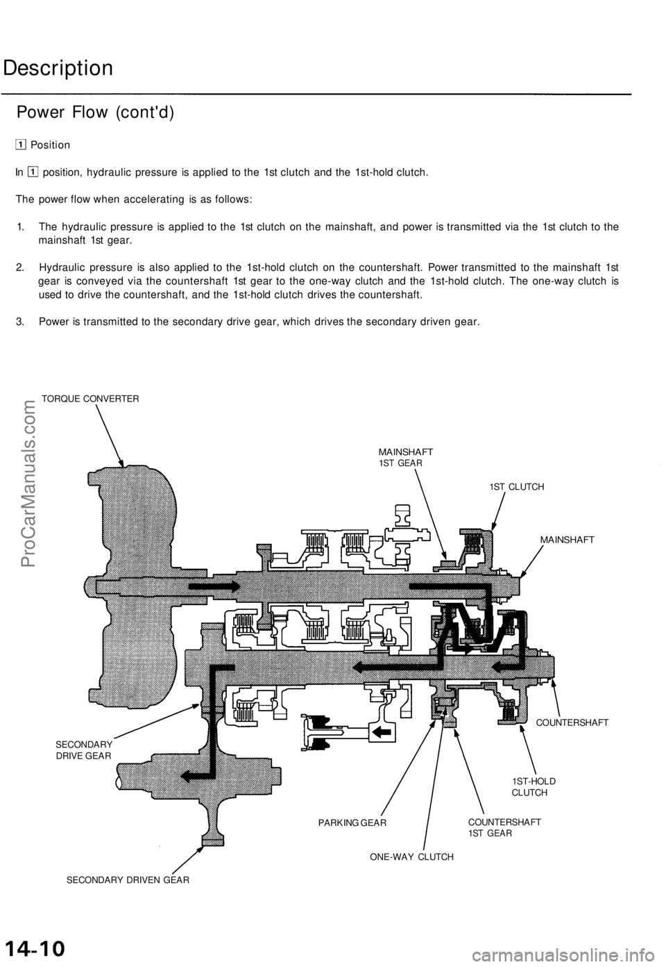
Position
In position, hydraulic pressure is applied to the 1st clutch and the 1st-hold clutch.
The power flow when accelerating is as follows:
1. The hydraulic pressure is applied to the 1st clutch on the mainshaft, and power is transmitted via the 1st clutch to the
mainshaft 1st gear.
2. Hydraulic pressure is also applied to the 1st-hold clutch on the countershaft. Power transmitted to the mainshaft 1st
gear is conveyed via the countershaft 1st gear to the one-way clutch and the 1st-hold clutch. The one-way clutch is
used to drive the countershaft, and the 1st-hold clutch drives the countershaft.
3. Power is transmitted to the secondary drive gear, which drives the secondary driven gear.
TORQUE CONVERTER
MAINSHAFT
1ST GEAR
SECONDARY
DRIVE GEAR
1ST CLUTCH
MAINSHAFT
COUNTERSHAFT
1ST-HOLD
CLUTCH
COUNTERSHAFT
1ST GEAR
ONE-WAY CLUTCH
SECONDARY DRIVEN GEAR
PARKING GEARProCarManuals.com
Page 944 of 1771
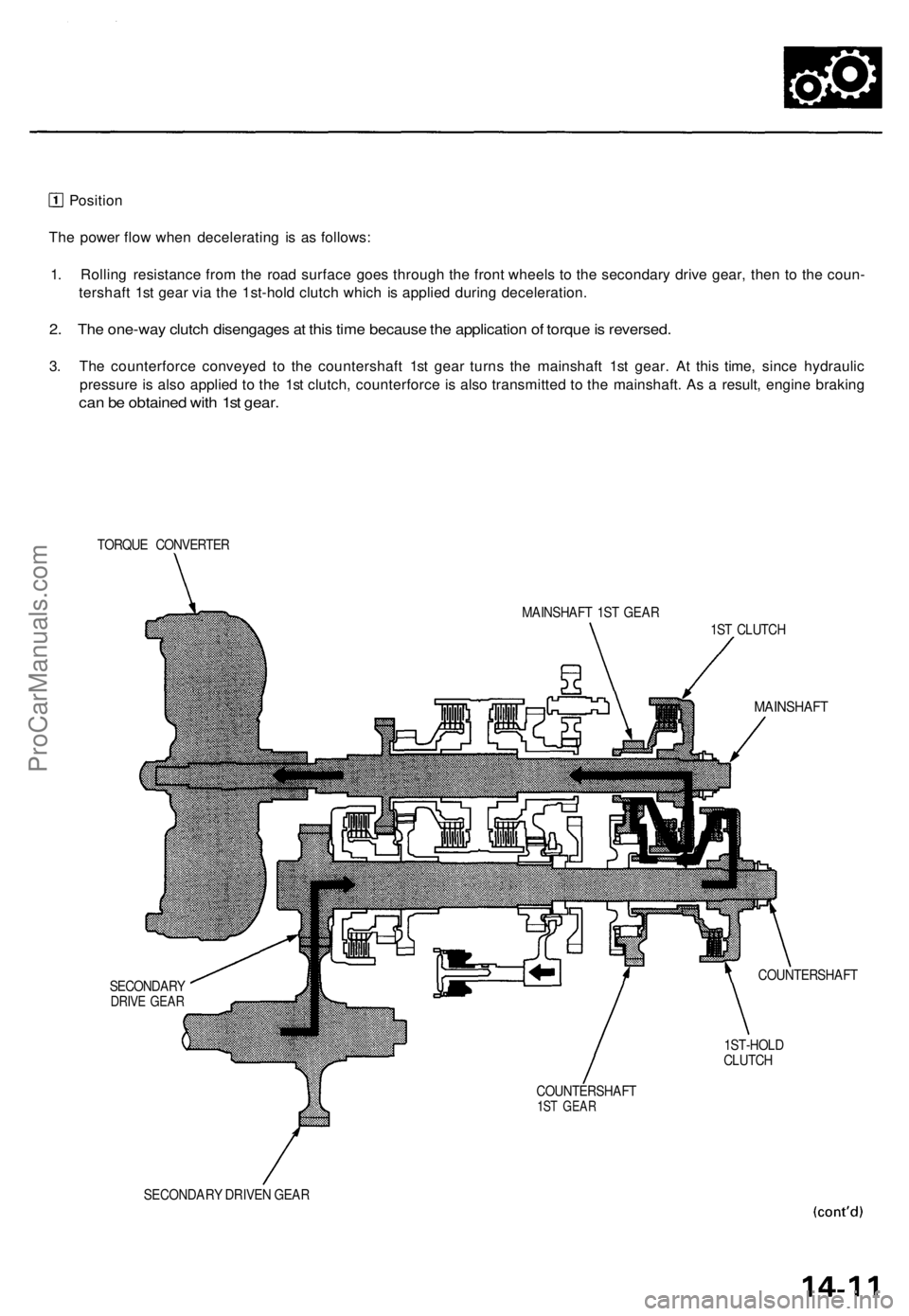
Position
The power flow when decelerating is as follows:
1. Rolling resistance from the road surface goes through the front wheels to the secondary drive gear, then to the coun-
tershaft 1st gear via the 1st-hold clutch which is applied during deceleration.
2. The one-way clutch disengages at this time because the application of torque is reversed.
3. The counterforce conveyed to the countershaft 1st gear turns the mainshaft 1st gear. At this time, since hydraulic
pressure is also applied to the 1st clutch, counterforce is also transmitted to the mainshaft. As a result, engine braking
can be obtained with 1st gear.
TORQUE CONVERTER
MAINSHAFT 1ST GEAR
1ST CLUTCH
MAINSHAFT
SECONDARY
DRIVE GEAR
COUNTERSHAFT
1ST-HOLD
CLUTCH
COUNTERSHAFT
1ST GEAR
SECONDARY DRIVEN GEARProCarManuals.com
Page 945 of 1771
Description
Power Flow (cont'd)
Position
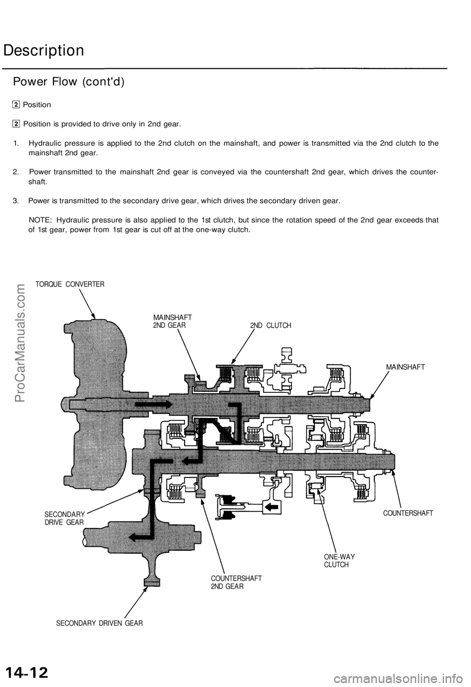
Position is provided to drive only in 2nd gear.
1. Hydraulic pressure is applied to the 2nd clutch on the mainshaft, and power is transmitted via the 2nd clutch to the
mainshaft 2nd gear.
2. Power transmitted to the mainshaft 2nd gear is conveyed via the countershaft 2nd gear, which drives the counter-
shaft.
3. Power is transmitted to the secondary drive gear, which drives the secondary driven gear.
NOTE: Hydraulic pressure is also applied to the 1st clutch, but since the rotation speed of the 2nd gear exceeds that
of 1st gear, power from 1st gear is cut off at the one-way clutch.
TORQUE CONVERTER
2ND CLUTCH
MAINSHAFT
SECONDARY
DRIVE GEAR
COUNTERSHAFT
ONE-WAY
CLUTCH
COUNTERSHAFT
2ND GEAR
SECONDARY DRIVEN GEAR
MAINSHAFT
2ND GEARProCarManuals.com
Page 946 of 1771
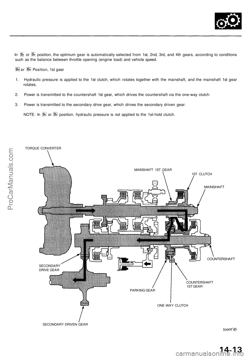
In or position, the optimum gear is automatically selected from 1st, 2nd, 3rd, and 4th gears, according to conditions
such as the balance between throttle opening (engine load) and vehicle speed.
or Position, 1st gear
1. Hydraulic pressure is applied to the 1st clutch, which rotates together with the mainshaft, and the mainshaft 1st gear
rotates.
2. Power is transmitted to the countershaft 1st gear, which drives the countershaft via the one-way clutch.
3. Power is transmitted to the secondary drive gear, which drives the secondary driven gear.
NOTE: In or position, hydraulic pressure is not applied to the 1st-hold clutch.
TORQUE CONVERTER
MAINSHAFT 1ST GEAR
1ST CLUTCH
MAINSHAFT
COUNTERSHAFT
COUNTERSHAFT
1ST GEAR
ONE-WAY CLUTCH
SECONDARY DRIVEN GEAR
PARKING GEAR
SECONDARY
DRIVE GEARProCarManuals.com
Page 947 of 1771
Power Flow (cont'd)
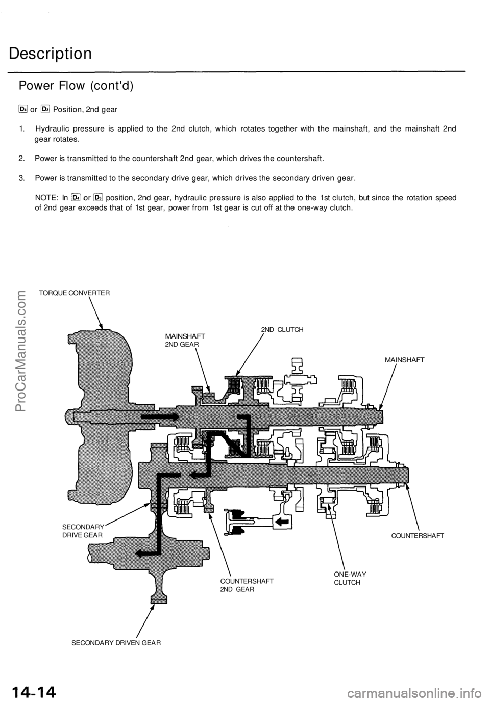
or Position, 2nd gear
1. Hydraulic pressure is applied to the 2nd clutch, which rotates together with the mainshaft, and the mainshaft 2nd
gear rotates.
2. Power is transmitted to the countershaft 2nd gear, which drives the countershaft.
3. Power is transmitted to the secondary drive gear, which drives the secondary driven gear.
NOTE: In or position, 2nd gear, hydraulic pressure is also applied to the 1st clutch, but since the rotation speed
of 2nd gear exceeds that of 1st gear, power from 1st gear is cut off at the one-way clutch.
TORQUE CONVERTER
2ND CLUTCH
MAINSHAFT
SECONDARY
DRIVE GEAR
COUNTERSHAFT
ONE-WAY
CLUTCH
SECONDARY DRIVEN GEAR
Description
COUNTERSHAFT
2ND GEAR
MAINSHAFT
2ND GEARProCarManuals.com
Page 948 of 1771
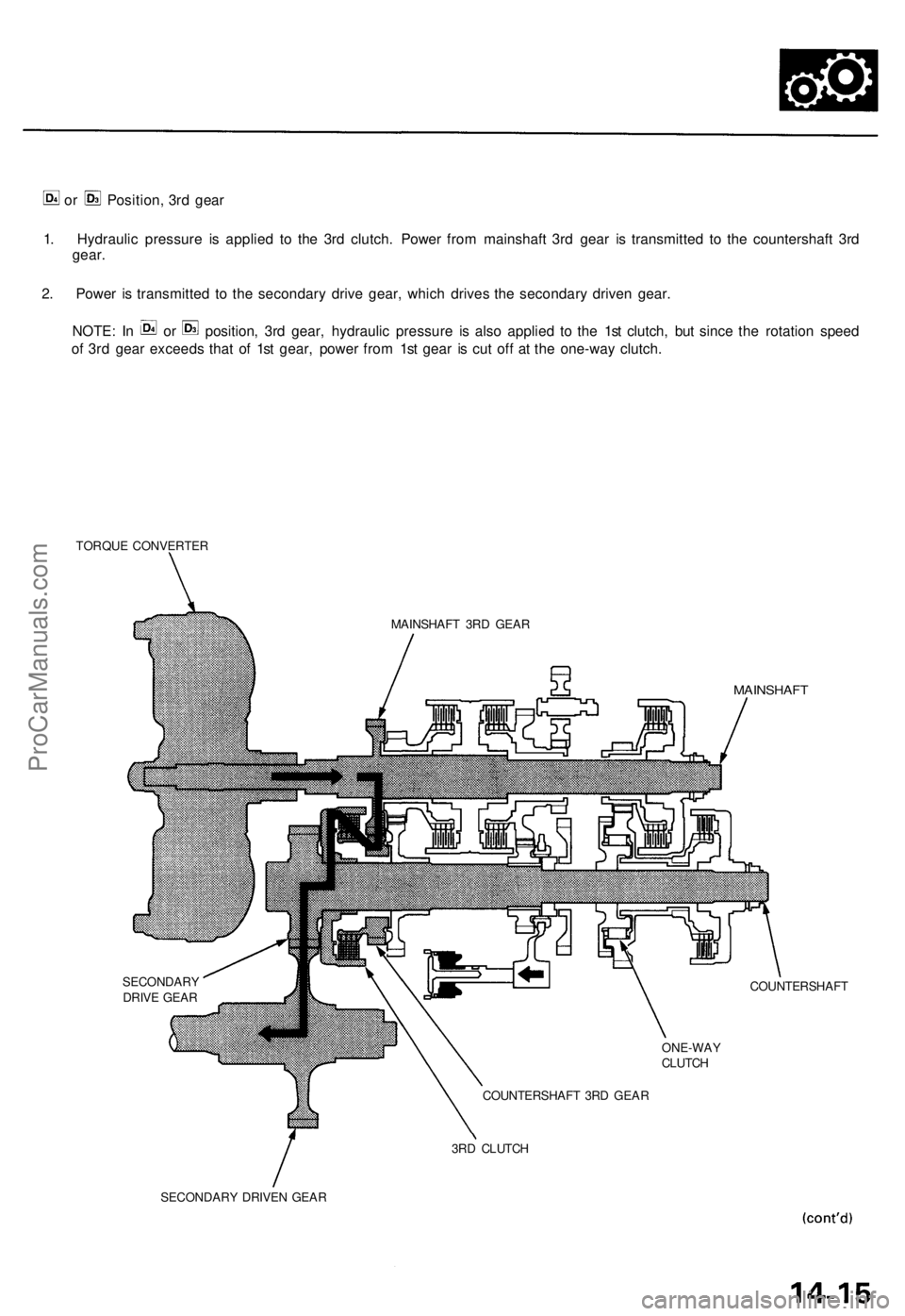
or Position, 3rd gear
1. Hydraulic pressure is applied to the 3rd clutch. Power from mainshaft 3rd gear is transmitted to the countershaft 3rd
gear.
2. Power is transmitted to the secondary drive gear, which drives the secondary driven gear.
NOTE: In or position, 3rd gear, hydraulic pressure is also applied to the 1st clutch, but since the rotation speed
of 3rd gear exceeds that of 1st gear, power from 1st gear is cut off at the one-way clutch.
TORQUE CONVERTER
MAINSHAFT 3RD GEAR
MAINSHAFT
SECONDARY
DRIVE GEAR
COUNTERSHAFT
ONE-WAY
CLUTCH
COUNTERSHAFT 3RD GEAR
3RD CLUTCH
SECONDARY DRIVEN GEARProCarManuals.com
Page 949 of 1771
Description
Power Flow (cont'd)
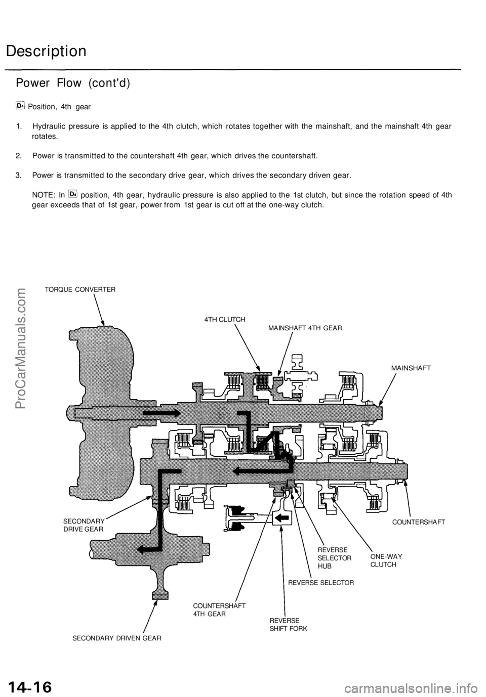
Position, 4th gear
1. Hydraulic pressure is applied to the 4th clutch, which rotates together with the mainshaft, and the mainshaft 4th gear
rotates.
2. Power is transmitted to the countershaft 4th gear, which drives the countershaft.
3. Power is transmitted to the secondary drive gear, which drives the secondary driven gear.
NOTE: In position, 4th gear, hydraulic pressure is also applied to the 1st clutch, but since the rotation speed of 4th
gear exceeds that of 1st gear, power from 1st gear is cut off at the one-way clutch.
TORQUE CONVERTER
4TH CLUTCH
MAINSHAFT 4TH GEAR
MAINSHAFT
SECONDARY
DRIVE GEAR
COUNTERSHAFT
ONE-WAY
CLUTCH
REVERSE
SHIFT FORK
SECONDARY DRIVEN GEAR
COUNTERSHAFT
4TH GEAR
REVERSE SELECTOR
REVERSE
SELECTOR
HUBProCarManuals.com
Page 950 of 1771
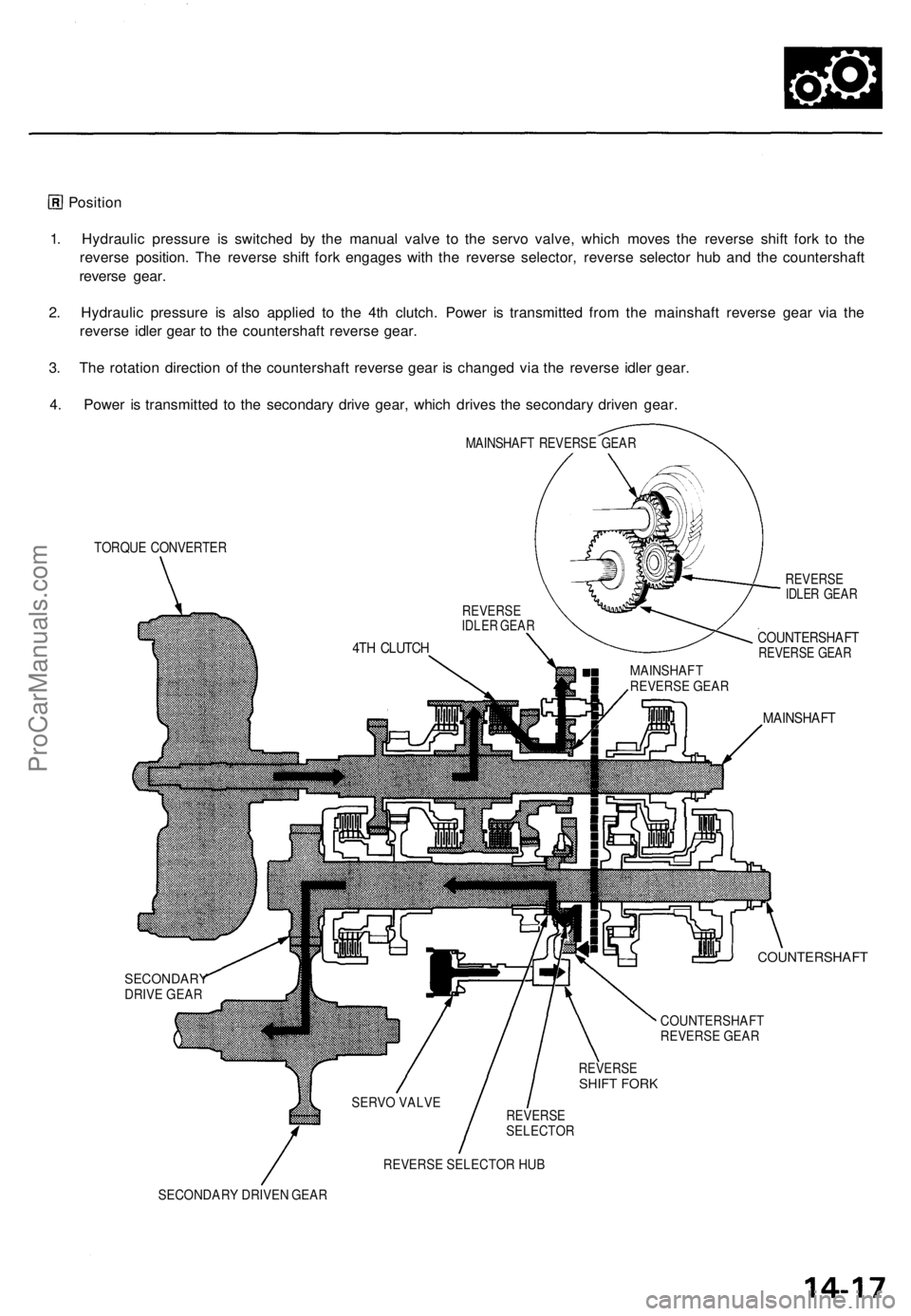
Position
1 . Hydrauli c pressur e i s switche d b y th e manua l valv e t o th e serv o valve , whic h move s th e revers e shif t for k t o th e
revers e position . Th e revers e shif t for k engage s wit h th e revers e selector , revers e selecto r hu b an d th e countershaf t
revers e gear .
2 . Hydrauli c pressur e i s als o applie d t o th e 4t h clutch . Powe r i s transmitte d fro m th e mainshaf t revers e gea r vi a th e
revers e idle r gea r t o th e countershaf t revers e gear .
3 . Th e rotatio n directio n o f th e countershaf t revers e gea r i s change d vi a th e revers e idle r gear .
4 . Powe r i s transmitte d t o th e secondar y driv e gear , whic h drive s th e secondar y drive n gear .
TORQU E CONVERTE R
REVERSEIDLER GEA R
COUNTERSHAF TREVERSE GEA R
MAINSHAF T
COUNTERSHAF T
SECONDARYDRIVE GEAR
COUNTERSHAFT
REVERSE GEAR
REVERSESHI FT FORK
REVERSESELECTOR
REVERSE SELECTOR HUB
SECONDARY DRIVEN GEAR SERVO VALVE MAINSHAF T
REVERSE
GEAR
REVERSEIDLER GEAR
4T H CLUTC H
MAINSHAF T REVERS E GEA R
ProCarManuals.com
Trending: battery capacity, tow bar, low beam, brake, fuel pump, radio antenna, engine coolant
