AUDI A6 2000 C5 / 2.G Changing Clutch 5Speed Manual Gearbox
Manufacturer: AUDI, Model Year: 2000, Model line: A6, Model: AUDI A6 2000 C5 / 2.GPages: 71, PDF Size: 1.82 MB
Page 11 of 71
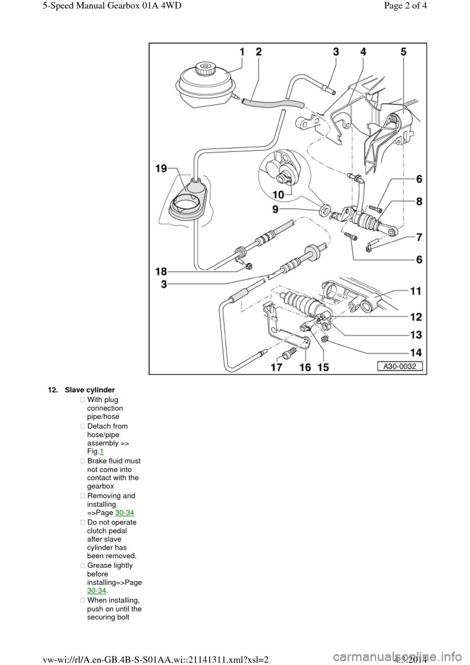
12.Slave cylinder ◆ With plug
connection
pipe/hose
◆ Detach from
hose/pipe
assembly =>
Fig.1
◆ Brake fluid must not come into
contact with the
gearbox
◆ Removing and
installing
=>Page 30-34
◆ Do not operate
clutch pedal
after slave
cylinder has
been removed.
◆ Grease lightly
before installing=>Page 30-34.
◆ When installing, push on until the securing bolt Page 2 of 45-Speed Manual Gearbox 01A 4WD4.3.2014vw-wi://rl/A.en-GB.4B-S-S01AA.wi::21141311.xml?xsl=2
Page 12 of 71
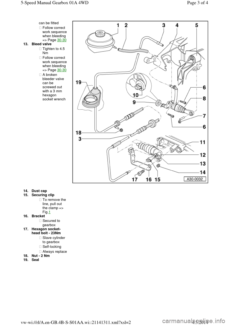
can be fitted
◆ Follow correct work sequence when bleeding
=> Page 30-30 13.Bleed valve
◆ Tighten to 4.5
Nm
◆ Follow correct work sequence when bleeding
=> Page 30-30 ◆ A broken
bleeder valve
can be
screwed out
with a 3 mm
hexagon
socket wrench 14.Dust cap 15.Securing clip
◆ To remove the
line, pull out
the clamp =>
Fig.1
16.Bracket
◆ Secured to
gearbox
17.Hexagon socket-
head bolt - 23Nm
◆ Slave cylinder
to gearbox
◆ Self-locking
◆ Always replace 18.Nut - 2 Nm
19.Seal Page 3 of 45-Speed Manual Gearbox 01A 4WD4.3.2014vw-wi://rl/A.en-GB.4B-S-S01AA.wi::21141311.xml?xsl=2
Page 13 of 71
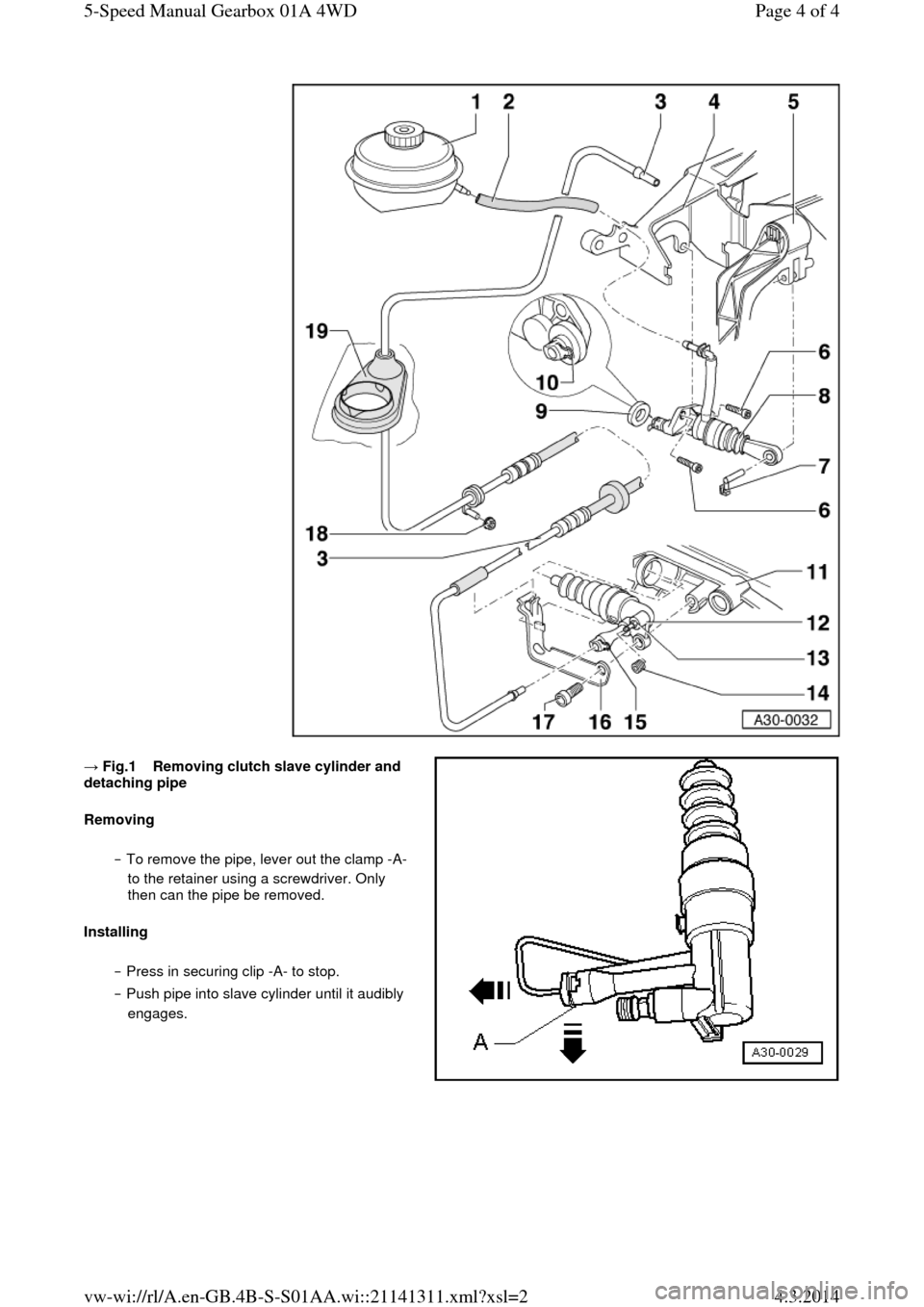
→ Fig.1 Removing clutch slave cylinder and detaching pipe
Removing
‒ To remove the pipe, lever out the clamp -A-
to the retainer using a screwdriver. Only
then can the pipe be removed.
Installing
‒ Press in securing clip -A- to stop.
‒ Push pipe into slave cylinder until it audibly
engages. Page 4 of 45-Speed Manual Gearbox 01A 4WD4.3.2014vw-wi://rl/A.en-GB.4B-S-S01AA.wi::21141311.xml?xsl=2
Page 14 of 71
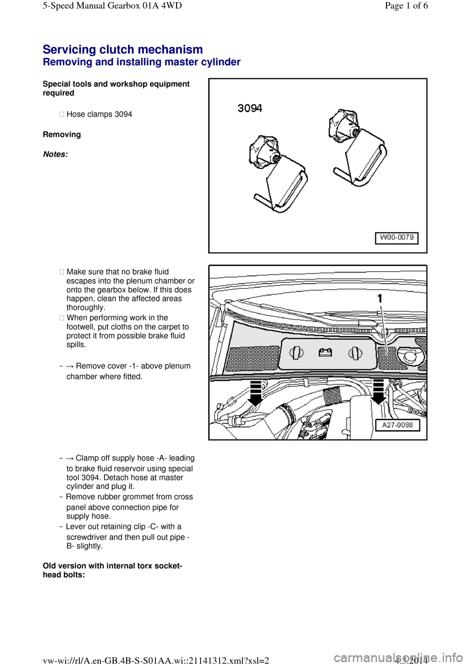
Servicing clutch mechanism Removing and installing master cylinder Special tools and workshop equipment required
◆ Hose clamps 3094
Removing
Notes: ◆ Make sure that no brake fluid escapes into the plenum chamber or onto the gearbox below. If this does
happen, clean the affected areas
thoroughly.
◆ When performing work in the
footwell, put cloths on the carpet to
protect it from possible brake fluid
spills.
‒ → Remove cover -1- above plenum
chamber where fitted. ‒ → Clamp off supply hose -A- leading to brake fluid reservoir using special
tool 3094. Detach hose at master
cylinder and plug it.
‒ Remove rubber grommet from cross
panel above connection pipe for
supply hose.
‒ Lever out retaining clip -C- with a
screwdriver and then pull out pipe -
B- slightly.
Old version with internal torx socket-
head bolts: Page 1 of 65-Speed Manual Gearbox 01A 4WD4.3.2014vw-wi://rl/A.en-GB.4B-S-S01AA.wi::21141312.xml?xsl=2
Page 15 of 71
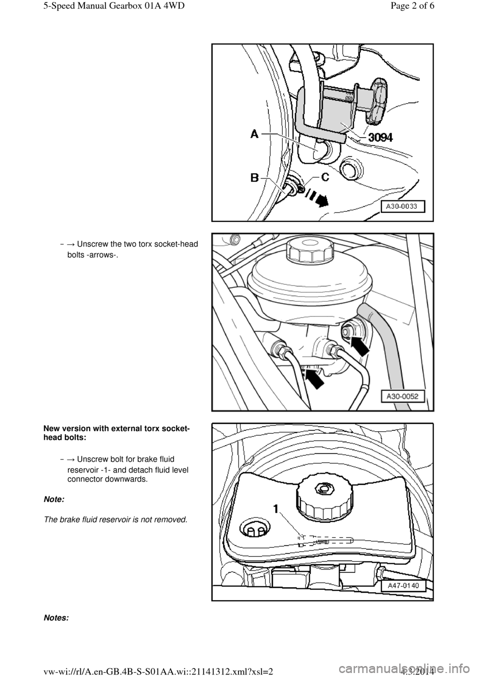
‒ → Unscrew the two torx socket-head bolts -arrows-. New version with external torx socket-head bolts:
‒ → Unscrew bolt for brake fluid
reservoir -1- and detach fluid level
connector downwards.
Note:
The brake fluid reservoir is not removed. Notes: Page 2 of 65-Speed Manual Gearbox 01A 4WD4.3.2014vw-wi://rl/A.en-GB.4B-S-S01AA.wi::21141312.xml?xsl=2
Page 16 of 71
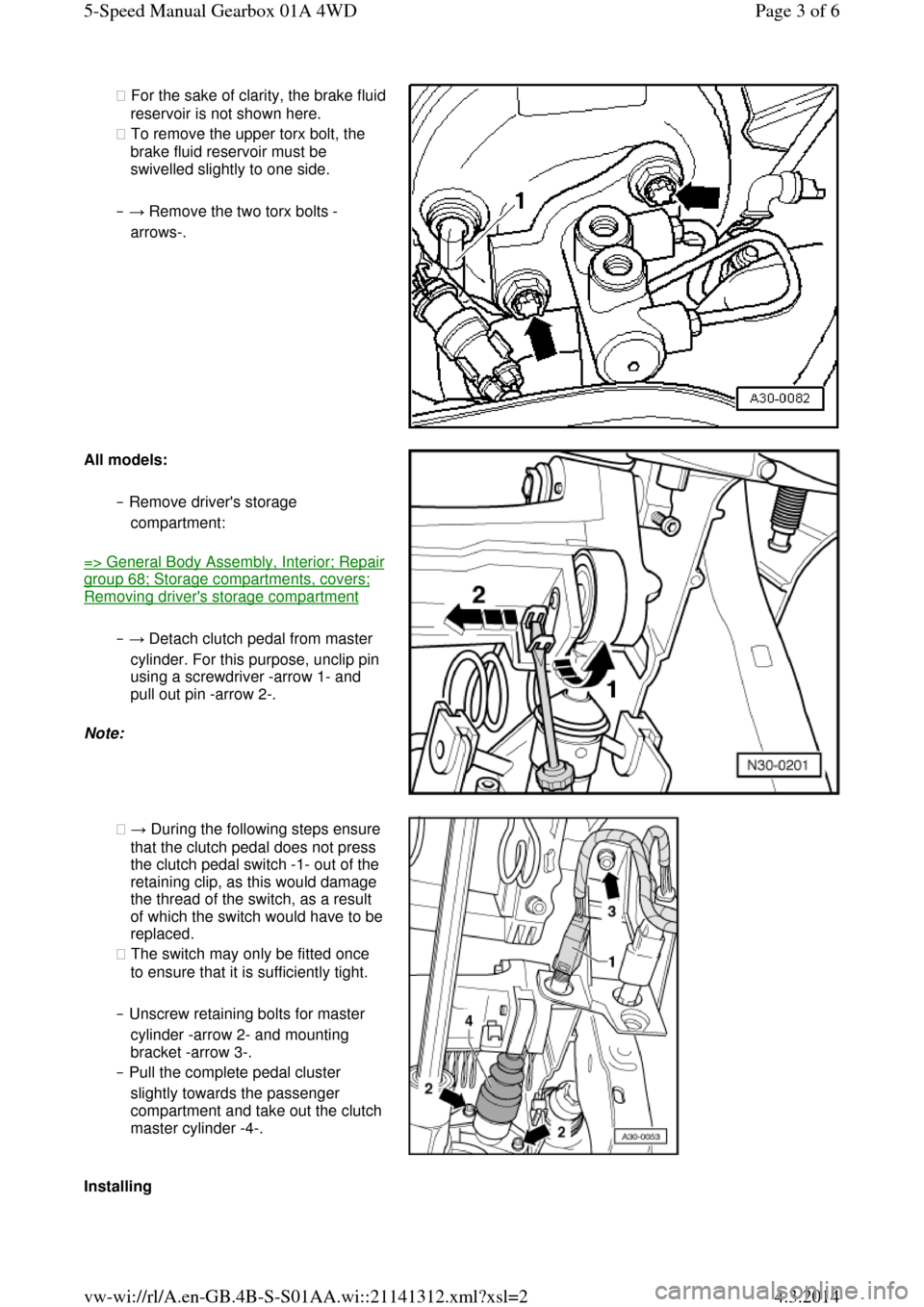
◆ For the sake of clarity, the brake fluid reservoir is not shown here.
◆ To remove the upper torx bolt, the
brake fluid reservoir must be
swivelled slightly to one side.
‒ → Remove the two torx bolts -
arrows-. All models: ‒ Remove driver's storage
compartment: => General Body Assembly, Interior; Repair group 68; Storage compartments, covers; Removing driver's storage compartment
‒ → Detach clutch pedal from master
cylinder. For this purpose, unclip pin
using a screwdriver -arrow 1- and
pull out pin -arrow 2-.
Note: ◆ → During the following steps ensure
that the clutch pedal does not press
the clutch pedal switch -1- out of the
retaining clip, as this would damage
the thread of the switch, as a result of which the switch would have to be replaced.
◆ The switch may only be fitted once
to ensure that it is sufficiently tight.
‒ Unscrew retaining bolts for master
cylinder -arrow 2- and mounting
bracket -arrow 3-.
‒ Pull the complete pedal cluster
slightly towards the passenger compartment and take out the clutch master cylinder -4-. Installing Page 3 of 65-Speed Manual Gearbox 01A 4WD4.3.2014vw-wi://rl/A.en-GB.4B-S-S01AA.wi::21141312.xml?xsl=2
Page 17 of 71
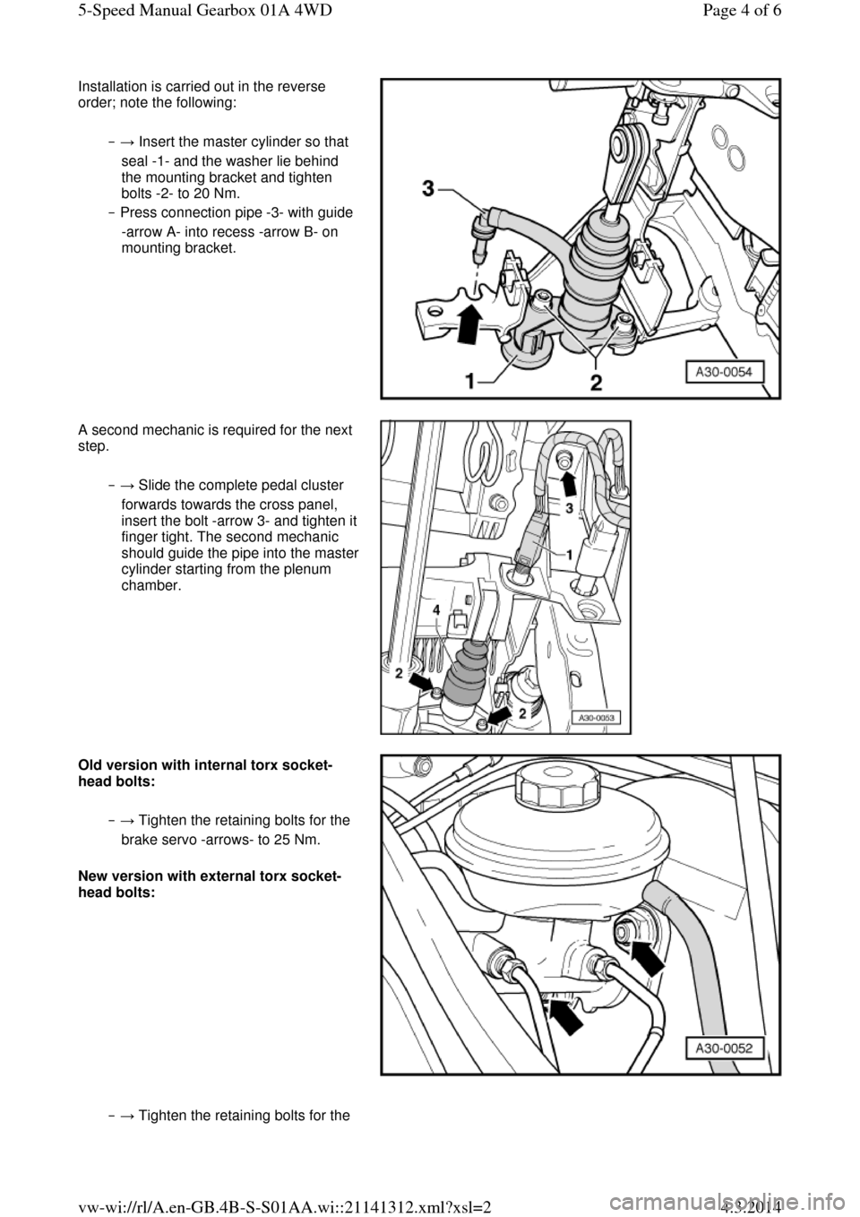
Installation is carried out in the reverse
order; note the following:
‒ → Insert the master cylinder so that
seal -1- and the washer lie behind
the mounting bracket and tighten
bolts -2- to 20 Nm.
‒ Press connection pipe -3- with guide
-arrow A- into recess -arrow B- on
mounting bracket. A second mechanic is required for the next
step.
‒ → Slide the complete pedal cluster
forwards towards the cross panel,
insert the bolt -arrow 3- and tighten it finger tight. The second mechanic should guide the pipe into the master cylinder starting from the plenum
chamber. Old version with internal torx socket-head bolts:
‒ → Tighten the retaining bolts for the
brake servo -arrows- to 25 Nm.
New version with external torx socket-
head bolts: ‒ → Tighten the retaining bolts for the Page 4 of 65-Speed Manual Gearbox 01A 4WD4.3.2014vw-wi://rl/A.en-GB.4B-S-S01AA.wi::21141312.xml?xsl=2
Page 18 of 71
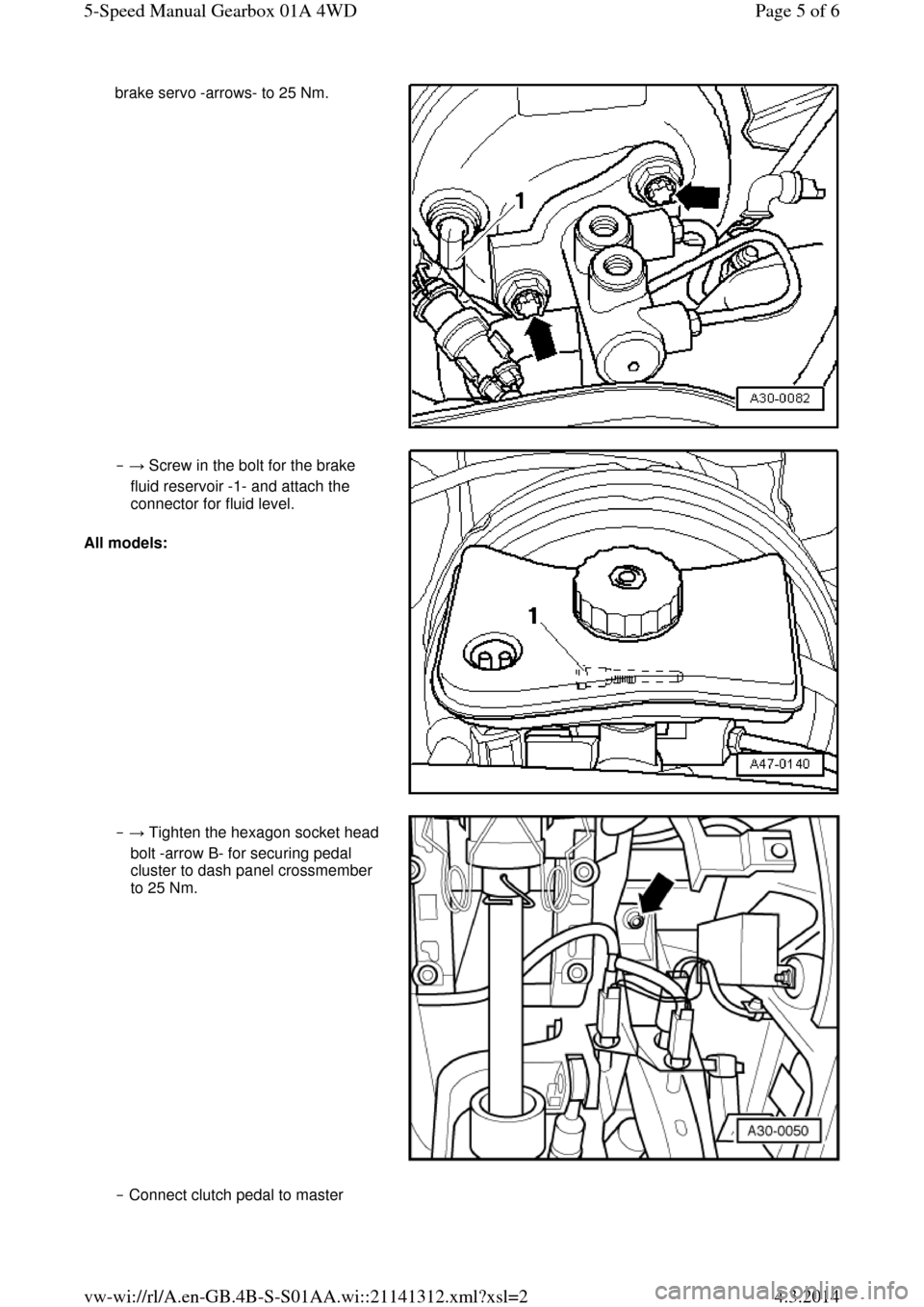
brake servo -arrows- to 25 Nm. ‒ → Screw in the bolt for the brake
fluid reservoir -1- and attach the
connector for fluid level.
All models: ‒ → Tighten the hexagon socket head
bolt -arrow B- for securing pedal
cluster to dash panel crossmember
to 25 Nm. ‒ Connect clutch pedal to master Page 5 of 65-Speed Manual Gearbox 01A 4WD4.3.2014vw-wi://rl/A.en-GB.4B-S-S01AA.wi::21141312.xml?xsl=2
Page 19 of 71
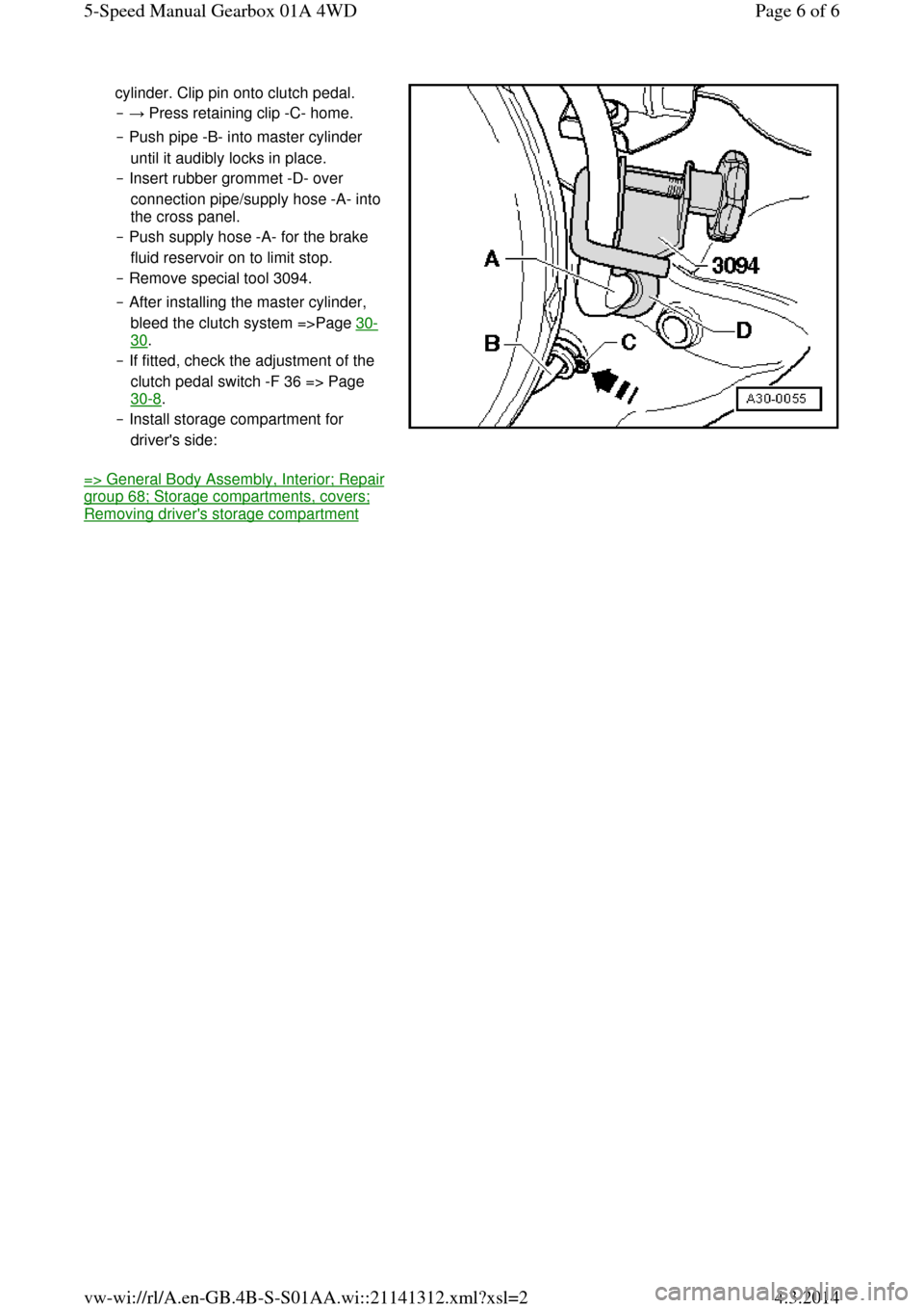
cylinder. Clip pin onto clutch pedal.
‒ → Press retaining clip -C- home.
‒ Push pipe -B- into master cylinder
until it audibly locks in place.
‒ Insert rubber grommet -D- over
connection pipe/supply hose -A- into
the cross panel.
‒ Push supply hose -A- for the brake
fluid reservoir on to limit stop.
‒ Remove special tool 3094.
‒ After installing the master cylinder,
bleed the clutch system =>Page 30-30.
‒ If fitted, check the adjustment of the
clutch pedal switch -F 36 => Page
30-8.
‒ Install storage compartment for
driver's side: => General Body Assembly, Interior; Repair group 68; Storage compartments, covers; Removing driver's storage compartment Page 6 of 65-Speed Manual Gearbox 01A 4WD4.3.2014vw-wi://rl/A.en-GB.4B-S-S01AA.wi::21141312.xml?xsl=2
Page 20 of 71
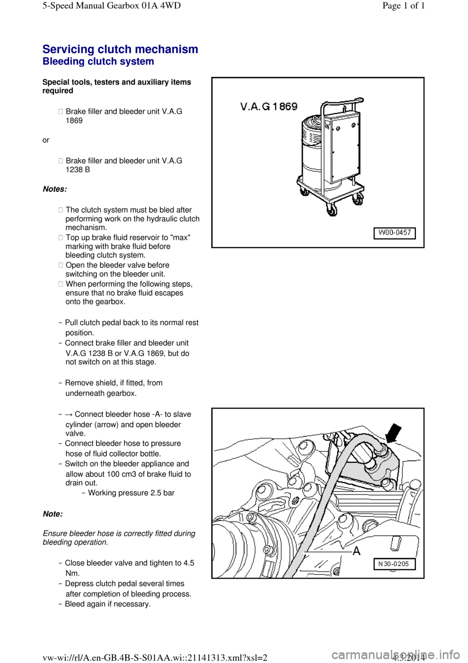
Servicing clutch mechanism Bleeding clutch system Special tools, testers and auxiliary items required
◆ Brake filler and bleeder unit V.A.G
1869
or
◆ Brake filler and bleeder unit V.A.G
1238 B
Notes:
◆ The clutch system must be bled after performing work on the hydraulic clutch mechanism.
◆ Top up brake fluid reservoir to "max"
marking with brake fluid before
bleeding clutch system.
◆ Open the bleeder valve before
switching on the bleeder unit.
◆ When performing the following steps,
ensure that no brake fluid escapes
onto the gearbox.
‒ Pull clutch pedal back to its normal rest position.
‒ Connect brake filler and bleeder unit
V.A.G 1238 B or V.A.G 1869, but do
not switch on at this stage.
‒ Remove shield, if fitted, from
underneath gearbox. ‒ → Connect bleeder hose -A- to slave
cylinder (arrow) and open bleeder
valve.
‒ Connect bleeder hose to pressure
hose of fluid collector bottle.
‒ Switch on the bleeder appliance and
allow about 100 cm3 of brake fluid to
drain out.
‒ Working pressure 2.5 bar
Note:
Ensure bleeder hose is correctly fitted during
bleeding operation.
‒ Close bleeder valve and tighten to 4.5
Nm.
‒ Depress clutch pedal several times
after completion of bleeding process.
‒ Bleed again if necessary. Page 1 of 15-Speed Manual Gearbox 01A 4WD4.3.2014vw-wi://rl/A.en-GB.4B-S-S01AA.wi::21141313.xml?xsl=2