AUDI A6 2000 C5 / 2.G Changing Clutch 5Speed Manual Gearbox
Manufacturer: AUDI, Model Year: 2000, Model line: A6, Model: AUDI A6 2000 C5 / 2.GPages: 71, PDF Size: 1.82 MB
Page 31 of 71
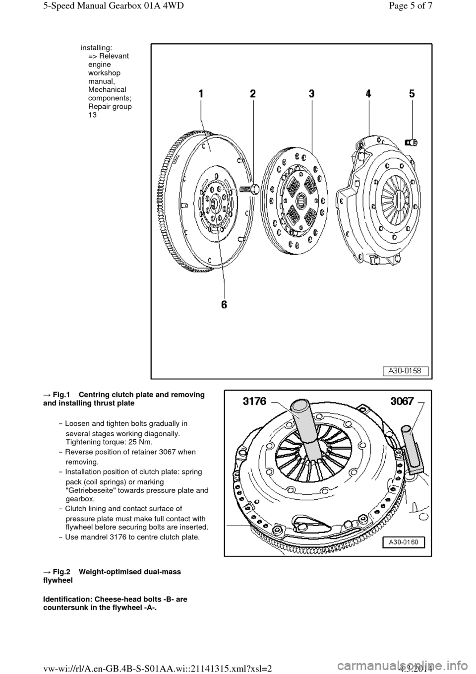
installing:
=> Relevant
engine
workshop
manual,
Mechanical
components;
Repair group
13 → Fig.1 Centring clutch plate and removing and installing thrust plate
‒ Loosen and tighten bolts gradually in
several stages working diagonally.
Tightening torque: 25 Nm.
‒ Reverse position of retainer 3067 when
removing.
‒ Installation position of clutch plate: spring
pack (coil springs) or marking
"Getriebeseite" towards pressure plate and
gearbox.
‒ Clutch lining and contact surface of
pressure plate must make full contact with
flywheel before securing bolts are inserted. ‒ Use mandrel 3176 to centre clutch plate.
→ Fig.2 Weight-optimised dual-mass flywheel
Identification: Cheese-head bolts -B- are
countersunk in the flywheel -A-. Page 5 of 75-Speed Manual Gearbox 01A 4WD4.3.2014vw-wi://rl/A.en-GB.4B-S-S01AA.wi::21141315.xml?xsl=2
Page 32 of 71
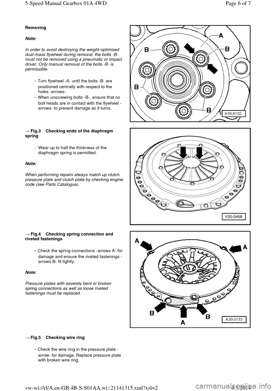
Removing Note:
In order to avoid destroying the weight-optimised
dual-mass flywheel during removal, the bolts -B-
must not be removed using a pneumatic or impact
driver. Only manual removal of the bolts -B- is permissible.
‒ Turn flywheel -A- until the bolts -B- are
positioned centrally with respect to the
holes -arrows-.
‒ When unscrewing bolts -B-, ensure that no
bolt heads are in contact with the flywheel -
arrows- to prevent damage as it turns. → Fig.3 Checking ends of the diaphragm spring
◆ Wear up to half the thickness of the
diaphragm spring is permitted.
Note:
When performing repairs always match up clutch pressure plate and clutch plate by checking engine code (see Parts Catalogue).
→ Fig.4 Checking spring connection and riveted fastenings
‒ Check the spring connections -arrows A- for damage and ensure the riveted fastenings -
arrows B- fit tightly.
Note:
Pressure plates with severely bent or broken
spring connections as well as loose riveted
fastenings must be replaced.
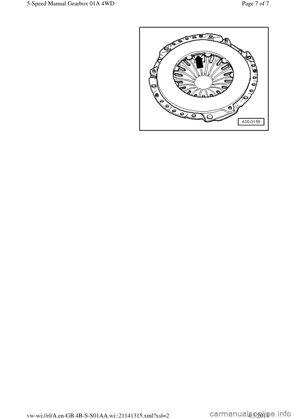
→ Fig.5 Checking wire ring ‒ Check the wire ring in the pressure plate -
arrow- for damage. Replace pressure plate
with broken wire ring. Page 6 of 75-Speed Manual Gearbox 01A 4WD4.3.2014vw-wi://rl/A.en-GB.4B-S-S01AA.wi::21141315.xml?xsl=2
Page 33 of 71
Page 7 of 75-Speed Manual Gearbox 01A 4WD4.3.2014vw-wi://rl/A.en-GB.4B-S-S01AA.wi::21141315.xml?xsl=2
Page 34 of 71
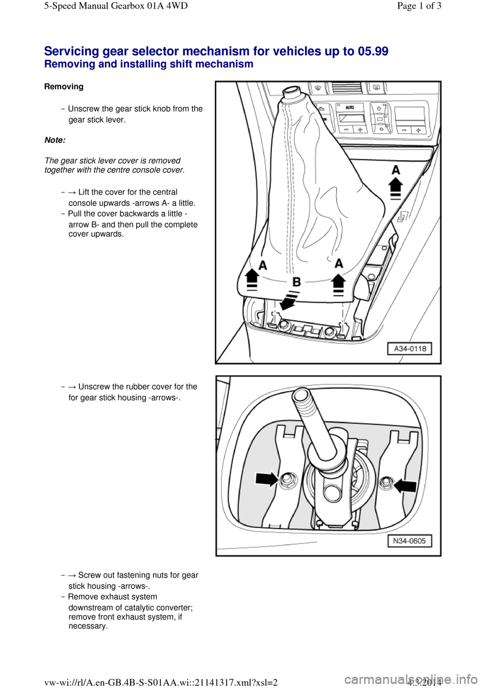
Servicing gear selector mechanism for vehicles up to 05.99 Removing and installing shift mechanism Removing ‒ Unscrew the gear stick knob from the gear stick lever.
Note:
The gear stick lever cover is removed
together with the centre console cover.
‒ → Lift the cover for the central
console upwards -arrows A- a little.
‒ Pull the cover backwards a little -
arrow B- and then pull the complete
cover upwards. ‒ → Unscrew the rubber cover for the
for gear stick housing -arrows-. ‒ → Screw out fastening nuts for gear
stick housing -arrows-.
‒ Remove exhaust system
downstream of catalytic converter;
remove front exhaust system, if
necessary. Page 1 of 35-Speed Manual Gearbox 01A 4WD4.3.2014vw-wi://rl/A.en-GB.4B-S-S01AA.wi::21141317.xml?xsl=2
Page 35 of 71
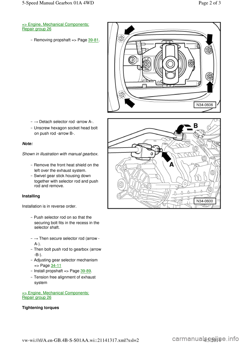
=> Engine, Mechanical Components; Repair group 26
‒ Removing propshaft => Page 39-81. ‒ → Detach selector rod -arrow A-.
‒ Unscrew hexagon socket head bolt
on push rod -arrow B-.
Note:
Shown in illustration with manual gearbox.
‒ Remove the front heat shield on the
left over the exhaust system.
‒ Swivel gear stick housing down
together with selector rod and push
rod and remove.
Installing
Installation is in reverse order.
‒ Push selector rod on so that the
securing bolt fits in the recess in the
selector shaft. ‒ → Then secure selector rod (arrow -
A-).
‒ Then bolt push rod to gearbox (arrow -B-).
‒ Adjusting gear selector mechanism
=> Page 34-11
‒ Install propshaft => Page 39-89.
‒ Tension free alignment of exhaust
system
=> Engine, Mechanical Components; Repair group 26
Tightening torques Page 2 of 35-Speed Manual Gearbox 01A 4WD4.3.2014vw-wi://rl/A.en-GB.4B-S-S01AA.wi::21141317.xml?xsl=2
Page 36 of 71
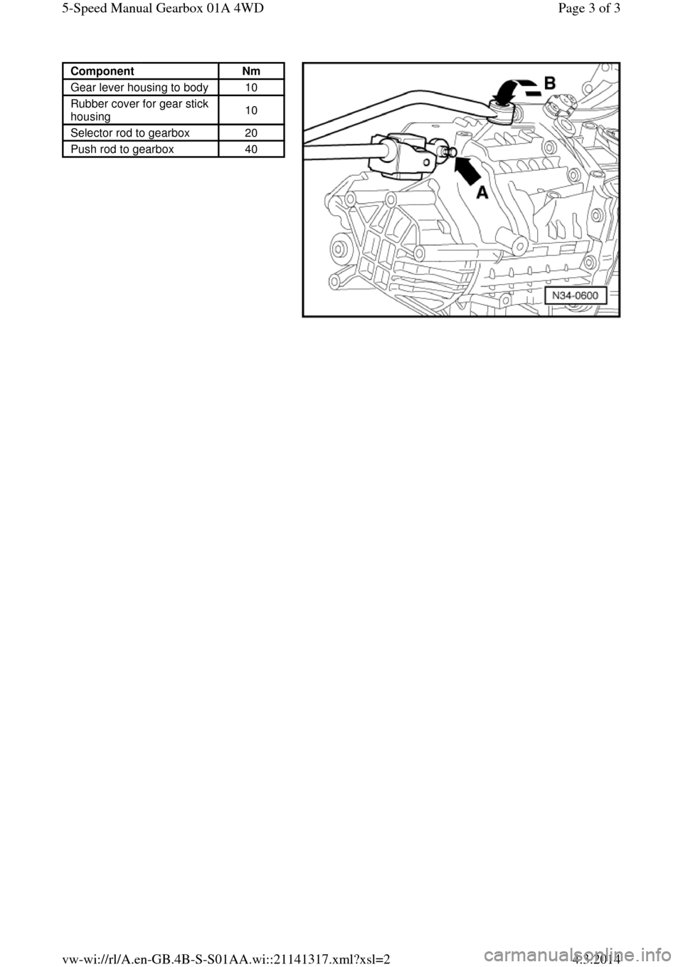
Component Nm
Gear lever housing to body 10
Rubber cover for gear stick
housing 10
Selector rod to gearbox 20
Push rod to gearbox 40 Page 3 of 35-Speed Manual Gearbox 01A 4WD4.3.2014vw-wi://rl/A.en-GB.4B-S-S01AA.wi::21141317.xml?xsl=2
Page 37 of 71
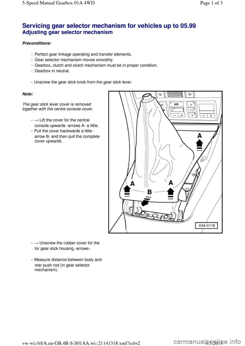
Servicing gear selector mechanism for vehicles up to 05.99 Adjusting gear selector mechanism
Preconditions:
◆ Perfect gear linkage operating and transfer elements.
◆ Gear selector mechanism moves smoothly.
◆ Gearbox, clutch and clutch mechanism must be in proper condition.
◆ Gearbox in neutral.
‒ Unscrew the gear stick knob from the gear stick lever. Note:
The gear stick lever cover is removed
together with the centre console cover.
‒ → Lift the cover for the central
console upwards -arrows A- a little.
‒ Pull the cover backwards a little -
arrow B- and then pull the complete
cover upwards.
‒ → Unscrew the rubber cover for the
for gear stick housing -arrows-.
‒ Measure distance between body and rear push rod (in gear selector
mechanism). Page 1 of 35-Speed Manual Gearbox 01A 4WD4.3.2014vw-wi://rl/A.en-GB.4B-S-S01AA.wi::21141318.xml?xsl=2
Page 38 of 71
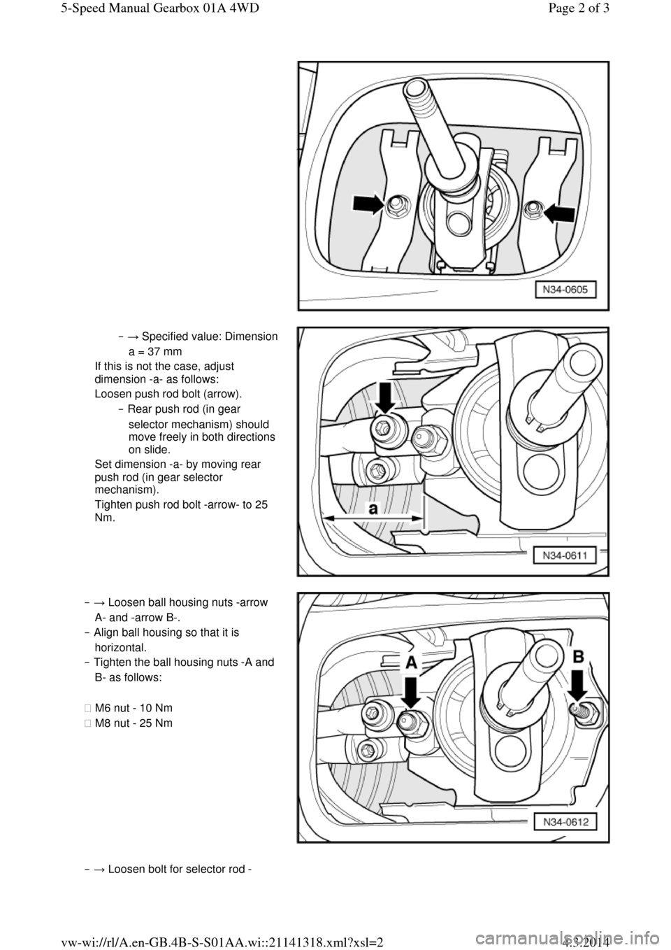
‒ → Specified value: Dimension a = 37 mm
If this is not the case, adjust
dimension -a- as follows:
Loosen push rod bolt (arrow).
‒ Rear push rod (in gear
selector mechanism) should
move freely in both directions
on slide.
Set dimension -a- by moving rear
push rod (in gear selector
mechanism).
Tighten push rod bolt -arrow- to 25
Nm. ‒ → Loosen ball housing nuts -arrow
A- and -arrow B-.
‒ Align ball housing so that it is
horizontal.
‒ Tighten the ball housing nuts -A and
B- as follows:
◆ M6 nut - 10 Nm
◆ M8 nut - 25 Nm ‒ → Loosen bolt for selector rod -Page 2 of 35-Speed Manual Gearbox 01A 4WD4.3.2014vw-wi://rl/A.en-GB.4B-S-S01AA.wi::21141318.xml?xsl=2
Page 39 of 71
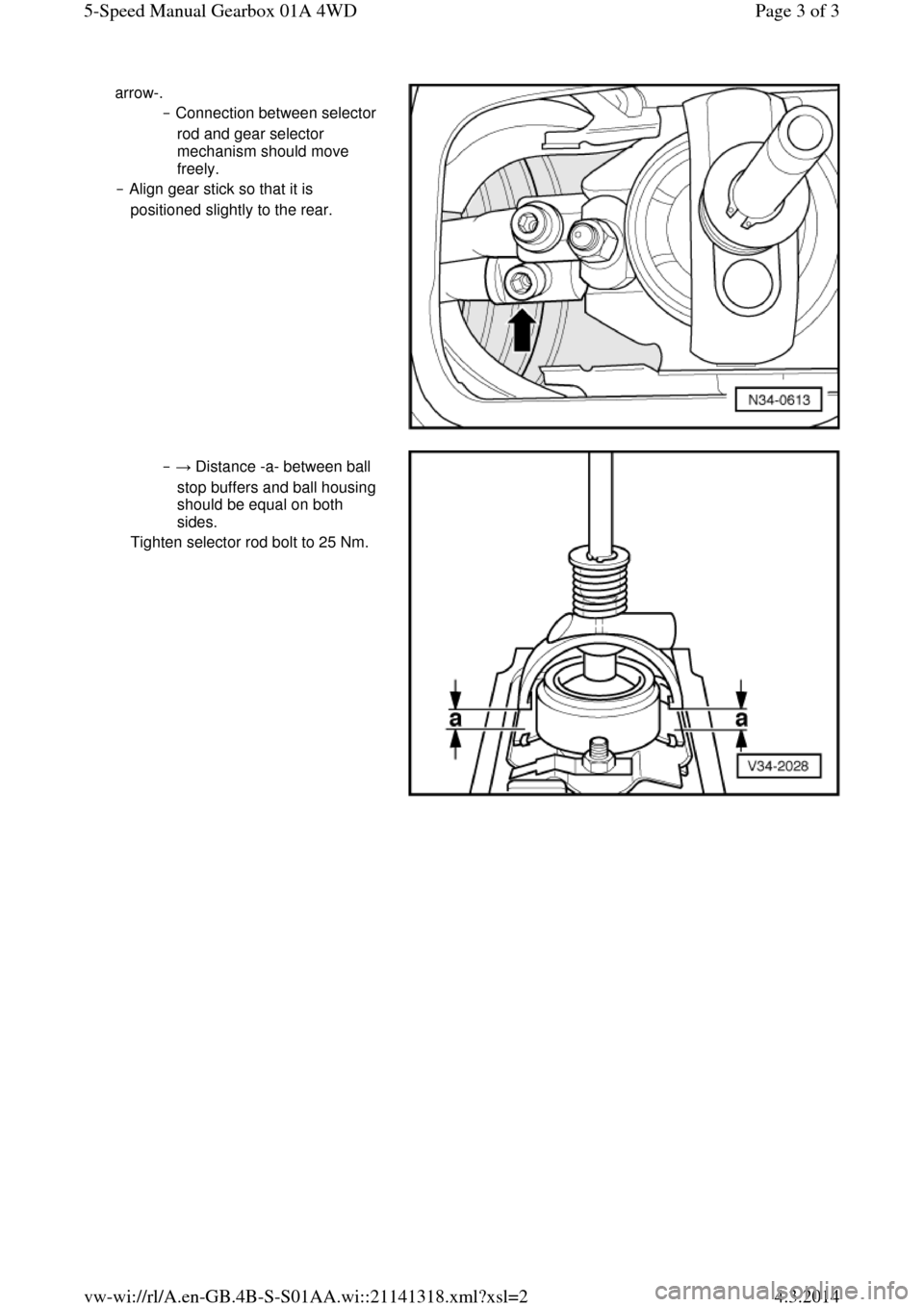
arrow-.
‒ Connection between selector
rod and gear selector
mechanism should move
freely.
‒ Align gear stick so that it is
positioned slightly to the rear. ‒ → Distance -a- between ball
stop buffers and ball housing
should be equal on both
sides.
Tighten selector rod bolt to 25 Nm. Page 3 of 35-Speed Manual Gearbox 01A 4WD4.3.2014vw-wi://rl/A.en-GB.4B-S-S01AA.wi::21141318.xml?xsl=2
Page 40 of 71
Servicing gear selector mechanism for vehicles up to 05.99 Checking gear stick position
● The gear stick must rest in the 3rd/4th gear gate when the gearbox is in neutral.
‒ Depress clutch.
‒ Check that all gears can be engaged.
‒ Check operation of reverse gear lock.
‒ The gear stick should return by itself from the 5th/reverse gear gate into the 3rd/4th gear gate.
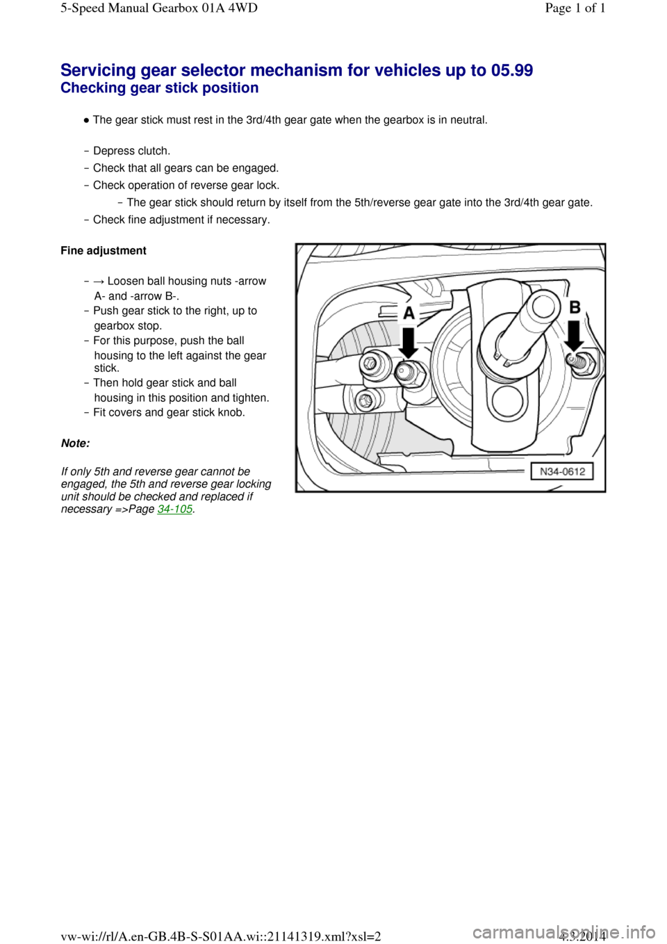
‒ Check fine adjustment if necessary. Fine adjustment ‒ → Loosen ball housing nuts -arrow
A- and -arrow B-.
‒ Push gear stick to the right, up to
gearbox stop.
‒ For this purpose, push the ball
housing to the left against the gear
stick.
‒ Then hold gear stick and ball
housing in this position and tighten.
‒ Fit covers and gear stick knob.
Note:
If only 5th and reverse gear cannot be
engaged, the 5th and reverse gear locking
unit should be checked and replaced if necessary =>Page 34-105. Page 1 of 15-Speed Manual Gearbox 01A 4WD4.3.2014vw-wi://rl/A.en-GB.4B-S-S01AA.wi::21141319.xml?xsl=2