CHERY TIGGO 2009 Service Repair Manual
Manufacturer: CHERY, Model Year: 2009, Model line: TIGGO, Model: CHERY TIGGO 2009Pages: 1903, PDF Size: 33.38 MB
Page 1291 of 1903
Downloaded from www.Manualslib.com manuals search engine GENERAL INFORMATION
Description
LTSM160027
09
09–17Chery Automobile Co., Ltd.
Page 1292 of 1903
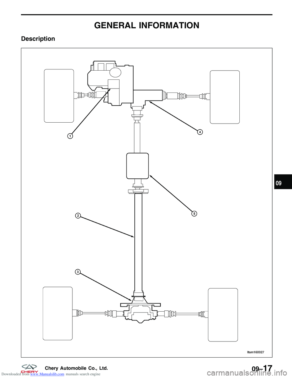
Downloaded from www.Manualslib.com manuals search engine The Tiggo 4WD is the first 4WD vehicle produced by Chery. The 4WD system is equipped with a QR523T transaxle
manufactured by Chery.
An active torque transfer system is used, and an interactive torque management system (ITM) is equipped to make
it possible to intelligently distribute the drive force for the front wheels and rear wheels according to different road
conditions. For example, on a smooth road, the vehicle utilizes front-wheel drive. When road conditions worsen, the
ITM will automatically switch to 4WD. The use of ITM allows the Tiggo vehicle to be more economical and more
efficient than the common 4WD system.
Operation
The intelligent 4WD system is controlled by an interactive torque management system (ITM) module. The ITM mod-
ule communicates with the Engine Control Module (ECM) and the Antilock Brake System (ABS) controller through the
CAN network. The ITM module collects data from sensors on the vehicle body to determine the condition of the drive
wheels. Based on the sensor inputs, the ITM module controls the ITM controller. The ITM controller will then distrib-
ute a portion of the torque to the rear drive axle as needed. The ITM controller works as an electromagnetic clutch.
Different torque can be transferred by changing the electric current of the ITM controller. The ITM controller will be
able to distribute the torque of the front drive axle and the rear drive axle at different ratios according to the various
dynamic conditions of the vehicle.
Specification
Transaxle Specifications
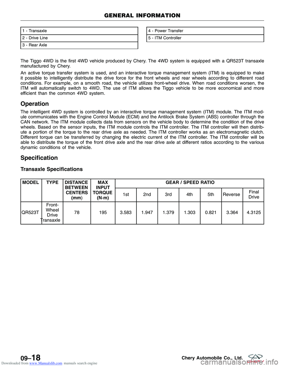
MODEL TYPE DISTANCEBETWEENCENTERS (mm) MAX
INPUT
TORQUE (N·m) GEAR / SPEED RATIO
1st 2nd 3rd 4th 5th Reverse Final
Drive
QR523T Front-
Wheel Drive
Transaxle 78 195 3.583 1.947 1.379 1.303 0.821 3.364 4.3125
1 - Transaxle
2 - Drive Line
3 - Rear Axle4 - Power Transfer
5 - ITM Controller
GENERAL INFORMATION
LTSM160027
09–18Chery Automobile Co., Ltd.
Page 1293 of 1903
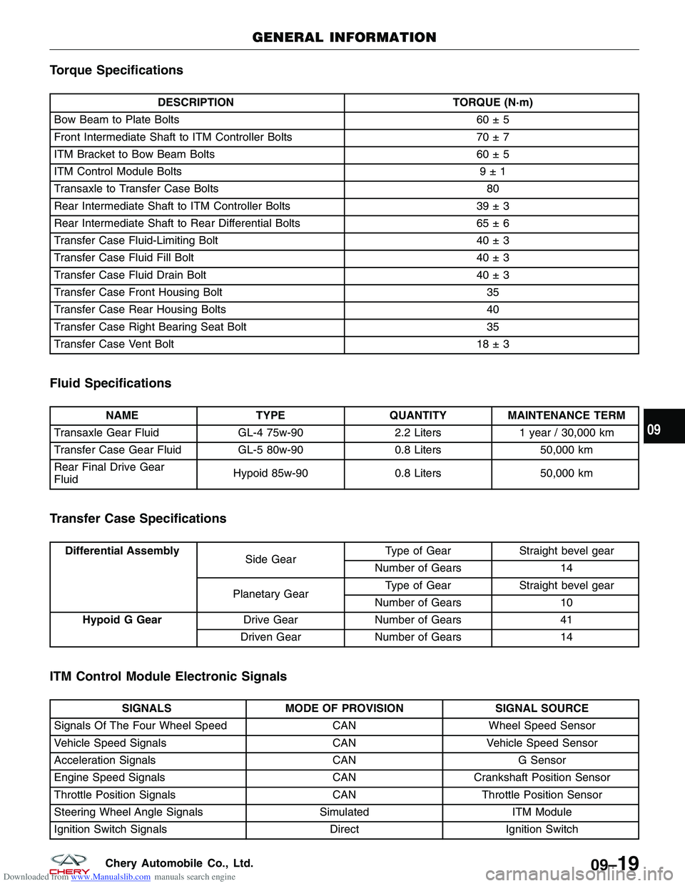
Downloaded from www.Manualslib.com manuals search engine Torque Specifications
DESCRIPTIONTORQUE (N·m)
Bow Beam to Plate Bolts 60 ± 5
Front Intermediate Shaft to ITM Controller Bolts 70 ± 7
ITM Bracket to Bow Beam Bolts 60 ± 5
ITM Control Module Bolts 9 ± 1
Transaxle to Transfer Case Bolts 80
Rear Intermediate Shaft to ITM Controller Bolts 39 ± 3
Rear Intermediate Shaft to Rear Differential Bolts 65 ± 6
Transfer Case Fluid-Limiting Bolt 40 ± 3
Transfer Case Fluid Fill Bolt 40 ± 3
Transfer Case Fluid Drain Bolt 40 ± 3
Transfer Case Front Housing Bolt 35
Transfer Case Rear Housing Bolts 40
Transfer Case Right Bearing Seat Bolt 35
Transfer Case Vent Bolt 18 ± 3
Fluid Specifications
NAMETYPEQUANTITYMAINTENANCE TERM
Transaxle Gear Fluid GL-4 75w-902.2 Liters1 year / 30,000 km
Transfer Case Gear Fluid GL-5 80w-900.8 Liters50,000 km
Rear Final Drive Gear
Fluid Hypoid 85w-90
0.8 Liters50,000 km
Transfer Case Specifications
Differential Assembly
Side GearType of Gear Straight bevel gear
Number of Gears 14
Planetary Gear Type of Gear
Straight bevel gear
Number of Gears 10
Hypoid G Gear Drive GearNumber of Gears 41
Driven Gear Number of Gears 14
ITM Control Module Electronic Signals
SIGNALSMODE OF PROVISION SIGNAL SOURCE
Signals Of The Four Wheel Speed CANWheel Speed Sensor
Vehicle Speed Signals CANVehicle Speed Sensor
Acceleration Signals CANG Sensor
Engine Speed Signals CANCrankshaft Position Sensor
Throttle Position Signals CANThrottle Position Sensor
Steering Wheel Angle Signals SimulatedITM Module
Ignition Switch Signals DirectIgnition Switch
GENERAL INFORMATION
09
09–19Chery Automobile Co., Ltd.
Page 1294 of 1903
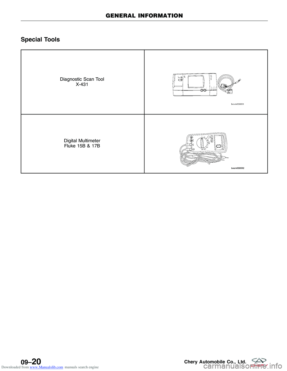
Downloaded from www.Manualslib.com manuals search engine Special Tools
Diagnostic Scan ToolX-431
Digital MultimeterFluke 15B & 17B
GENERAL INFORMATION
09–20Chery Automobile Co., Ltd.
Page 1295 of 1903
Downloaded from www.Manualslib.com manuals search engine ON-VEHICLE SERVICE
Interactive Torque Management (ITM) Controller
Description
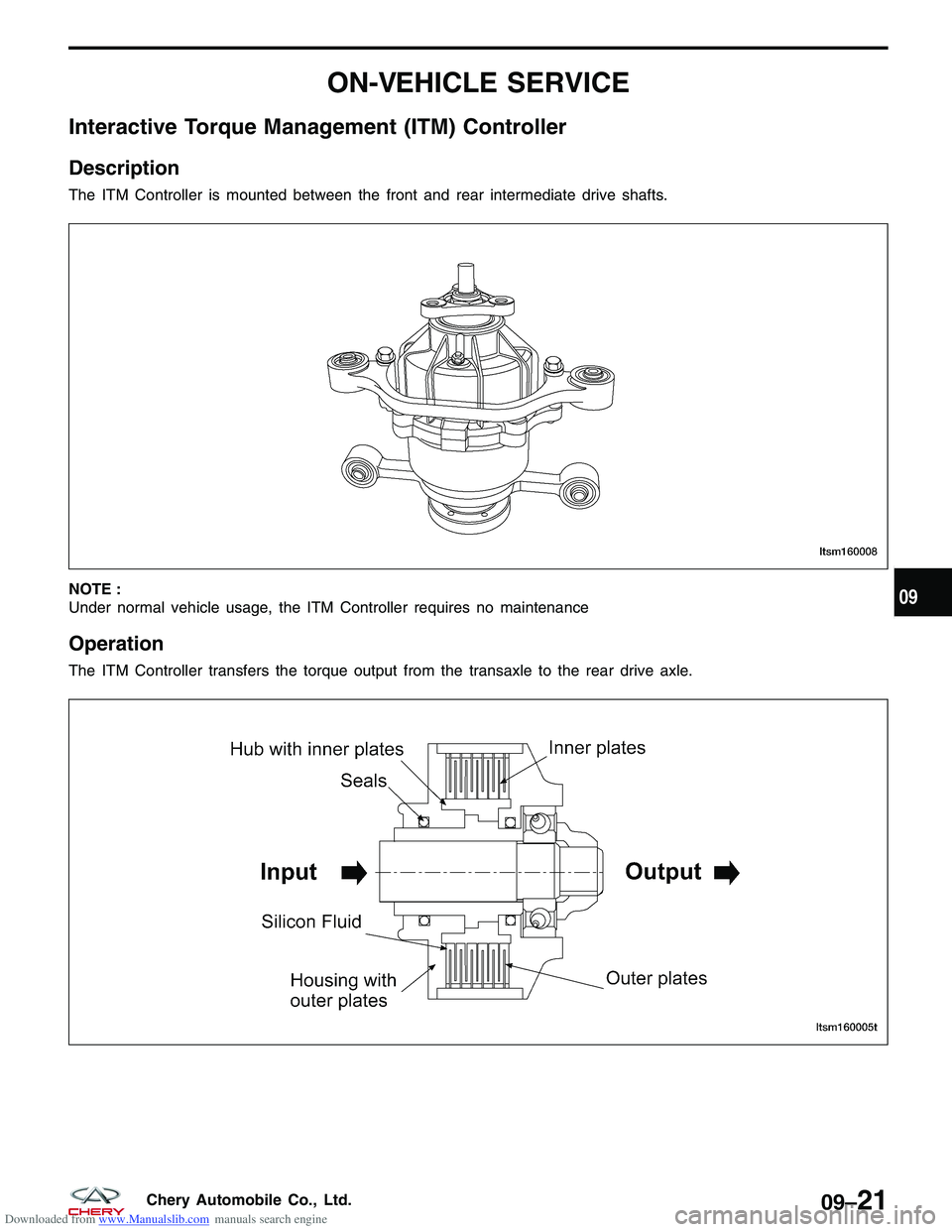
The ITM Controller is mounted between the front and rear intermediate drive shafts.
NOTE :
Under normal vehicle usage, the ITM Controller requires no maintenance
Operation
The ITM Controller transfers the torque output from the transaxle to the rear drive axle.
LTSM160008
LTSM160005T
09
09–21Chery Automobile Co., Ltd.
Page 1296 of 1903
Downloaded from www.Manualslib.com manuals search engine Removal & Installation
1. Raise and support the vehicle.
2. Remove the front intermediate drive shaft (See Front Intermediate Drive Shaft Removal & Installation in Section09 Driveline & Axle).
3. Remove the rear intermediate drive shaft (See Rear Intermediate Drive Shaft Removal & Installation in Section 09 Driveline & Axle).
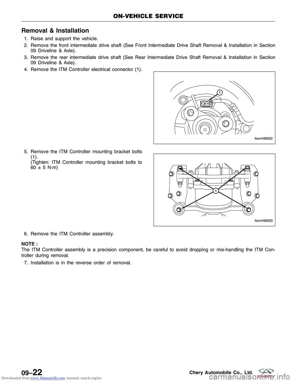
4. Remove the ITM Controller electrical connector (1).
5. Remove the ITM Controller mounting bracket bolts (1).
(Tighten: ITM Controller mounting bracket bolts to
60 ± 5 N·m)
6. Remove the ITM Controller assembly.
NOTE :
The ITM Controller assembly is a precision component, be careful to avoid dropping or mis-handling the ITM Con-
troller during removal. 7. Installation is in the reverse order of removal.
ON-VEHICLE SERVICE
LTSM160022
LTSM160023
09–22Chery Automobile Co., Ltd.
Page 1297 of 1903
Downloaded from www.Manualslib.com manuals search engine Interactive Torque Management (ITM) Control Module
Description
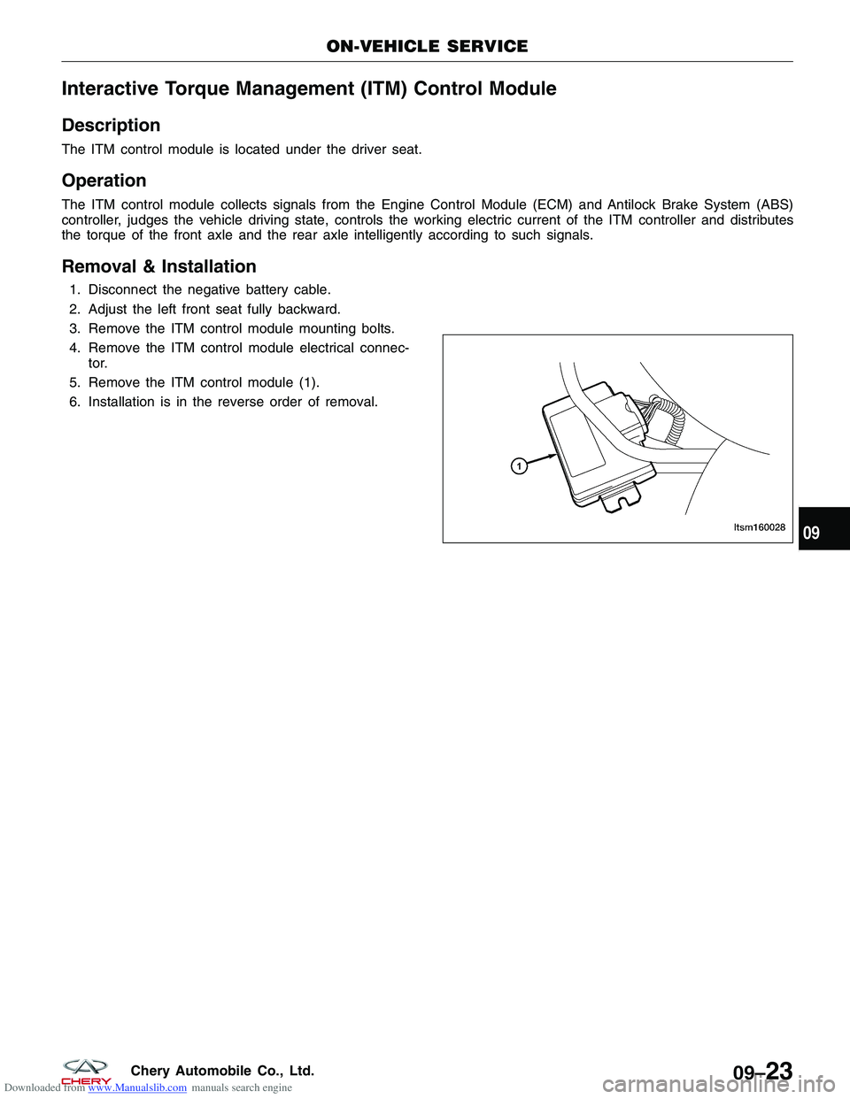
The ITM control module is located under the driver seat.
Operation
The ITM control module collects signals from the Engine Control Module (ECM) and Antilock Brake System (ABS)
controller, judges the vehicle driving state, controls the working electric current of the ITM controller and distributes
the torque of the front axle and the rear axle intelligently according to such signals.
Removal & Installation
1. Disconnect the negative battery cable.
2. Adjust the left front seat fully backward.
3. Remove the ITM control module mounting bolts.
4. Remove the ITM control module electrical connec-tor.
5. Remove the ITM control module (1).
6. Installation is in the reverse order of removal.
ON-VEHICLE SERVICE
LTSM16002809
09–23Chery Automobile Co., Ltd.
Page 1298 of 1903
Downloaded from www.Manualslib.com manuals search engine DRIVE SHAFT (4X4)
GENERAL INFORMATION09-25
Description 09-25
Operation 09-25
Specifications 09-25
DIAGNOSIS & TESTING09-26
Vehicle Inspection 09-26
Shudder Or Vibration During Acceleration 09-26
Clunking Noise During Acceleration 09-26 Shudder Or Vibration During Acceleration 09-26
Vibration At High Speeds 09-26
ON-VEHICLE SERVICE09-27
Front Intermediate Drive Shaft 09-27
Removal & Installation 09-27
Rear Intermediate Drive Shaft 09-27
Removal & Installation 09-27
09–24Chery Automobile Co., Ltd.
Page 1299 of 1903
Downloaded from www.Manualslib.com manuals search engine GENERAL INFORMATION
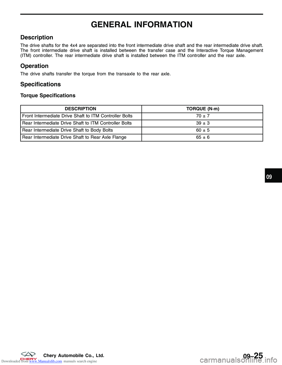
Description
The drive shafts for the 4x4 are separated into the front intermediate drive shaft and the rear intermediate drive shaft.
The front intermediate drive shaft is installed between the transfer case and the Interactive Torque Management
(ITM) controller. The rear intermediate drive shaft is installed between the ITM controller and the rear axle.
Operation
The drive shafts transfer the torque from the transaxle to the rear axle.
Specifications
Torque Specifications
DESCRIPTIONTORQUE (N·m)
Front Intermediate Drive Shaft to ITM Controller Bolts 70 ± 7
Rear Intermediate Drive Shaft to ITM Controller Bolts 39 ± 3
Rear Intermediate Drive Shaft to Body Bolts 60 ± 5
Rear Intermediate Drive Shaft to Rear Axle Flange 65 ± 6
09
09–25Chery Automobile Co., Ltd.
Page 1300 of 1903
Downloaded from www.Manualslib.com manuals search engine DIAGNOSIS & TESTING
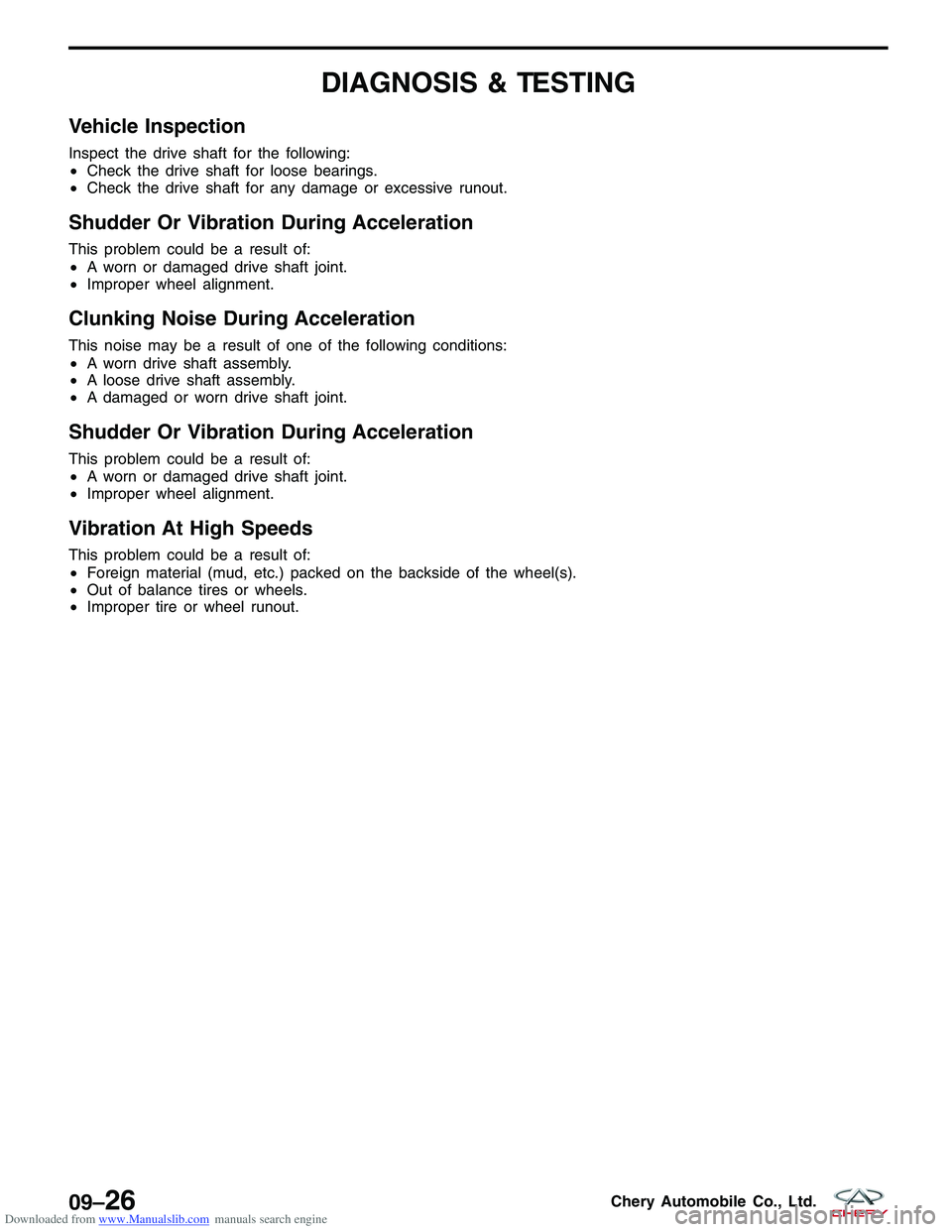
Vehicle Inspection
Inspect the drive shaft for the following:
•Check the drive shaft for loose bearings.
• Check the drive shaft for any damage or excessive runout.
Shudder Or Vibration During Acceleration
This problem could be a result of:
•A worn or damaged drive shaft joint.
• Improper wheel alignment.
Clunking Noise During Acceleration
This noise may be a result of one of the following conditions:
•A worn drive shaft assembly.
• A loose drive shaft assembly.
• A damaged or worn drive shaft joint.
Shudder Or Vibration During Acceleration
This problem could be a result of:
•A worn or damaged drive shaft joint.
• Improper wheel alignment.
Vibration At High Speeds
This problem could be a result of:
•Foreign material (mud, etc.) packed on the backside of the wheel(s).
• Out of balance tires or wheels.
• Improper tire or wheel runout.
09–26Chery Automobile Co., Ltd.