wiring CHEVROLET DYNASTY 1993 Manual PDF
[x] Cancel search | Manufacturer: CHEVROLET, Model Year: 1993, Model line: DYNASTY, Model: CHEVROLET DYNASTY 1993Pages: 2438, PDF Size: 74.98 MB
Page 388 of 2438
relay to starter solenoid for loose or corroded connec-
tions. Particularly at starter terminals.
² Repeat test. If engine still fails to crank properly,
trouble is within starter or starter mounted solenoid,
and it must be removed for repairs. Refer to Group
8B, Battery/Starter/Generator Service, Starter re-
placement.
STARTER RELAY TEST
WARNING: CHECK TO ENSURE THAT THE TRANS-
MISSION IS IN PARK OR NEUTRAL WITH THE
PARKING BRAKE APPLIED
(1) Verify battery condition. Battery must be in
good condition with a full charge before performing
any starter tests. Refer to Battery Tests. (2) Perform the preceding starter solenoid tests
BEFORE performing starter relay tests. Refer to
Starter Solenoid Test. (3) Locate and remove the starter relay. For
starter relay locations, refer to Starter Solenoid Test
(Fig. 13 or 14). (4) After the starter relay has been located and re-
moved, refer to Starter Relay Tests (Fig. 15).
NEUTRAL STARTING AND BACK-UP SWITCH
AUTOMATIC TRANSMISSION ONLY
For electrical diagnostics, when checking starter
circuits, refer to Starter Relay Tests (Fig. 15). For replacement of switch, refer to Group 21, Tran-
saxle, Neutral Starting and Switch Replacement.
STARTER INTERLOCK SWITCHÐCLUTCH PEDAL MOUNTED
MANUAL TRANSMISSION ONLY
For electrical diagnostics, refer to the Starter Relay
Tests. For replacement and/or adjustment of the switch,
refer to Group 6, Manual Transaxle Clutch, Manual
Transaxle Starter Interlock Switch.
IGNITION SWITCH TEST
After testing the starter solenoid and relay, test ig-
nition switch and wiring. Refer to Group 8D, Ignition
Systems, or the Front Wheel Drive Car Wiring Dia-
grams Service Manual. Check all wiring for opens or
shorts, and all connectors for being loose or corroded.
BENCH TESTING STARTER SOLENOID
(1) Disconnect field coil wire from field coil termi-
nal (Fig. 16 or 17). (2) Check for continuity between solenoid terminal
and field coil terminal with a continuity tester. Con-
tinuity should be detected (Fig. 18 or 19). (3) Check for continuity between solenoid terminal
and solenoid housing (Fig. 20 or 21). Continuity
should be detected. If continuity is detected, solenoid
is good. (4) If continuity is not detected in either test, sole-
noid has an open circuit and is defective. If equipped
with:
² BOSCH STARTER: Replace the solenoid.
² NIPPONDENSO STARTER: Replace the starter
assembly.
8A - 16 BATTERY/STARTING/CHARGING SYSTEMS DIAGNOSTICS Ä
Page 393 of 2438
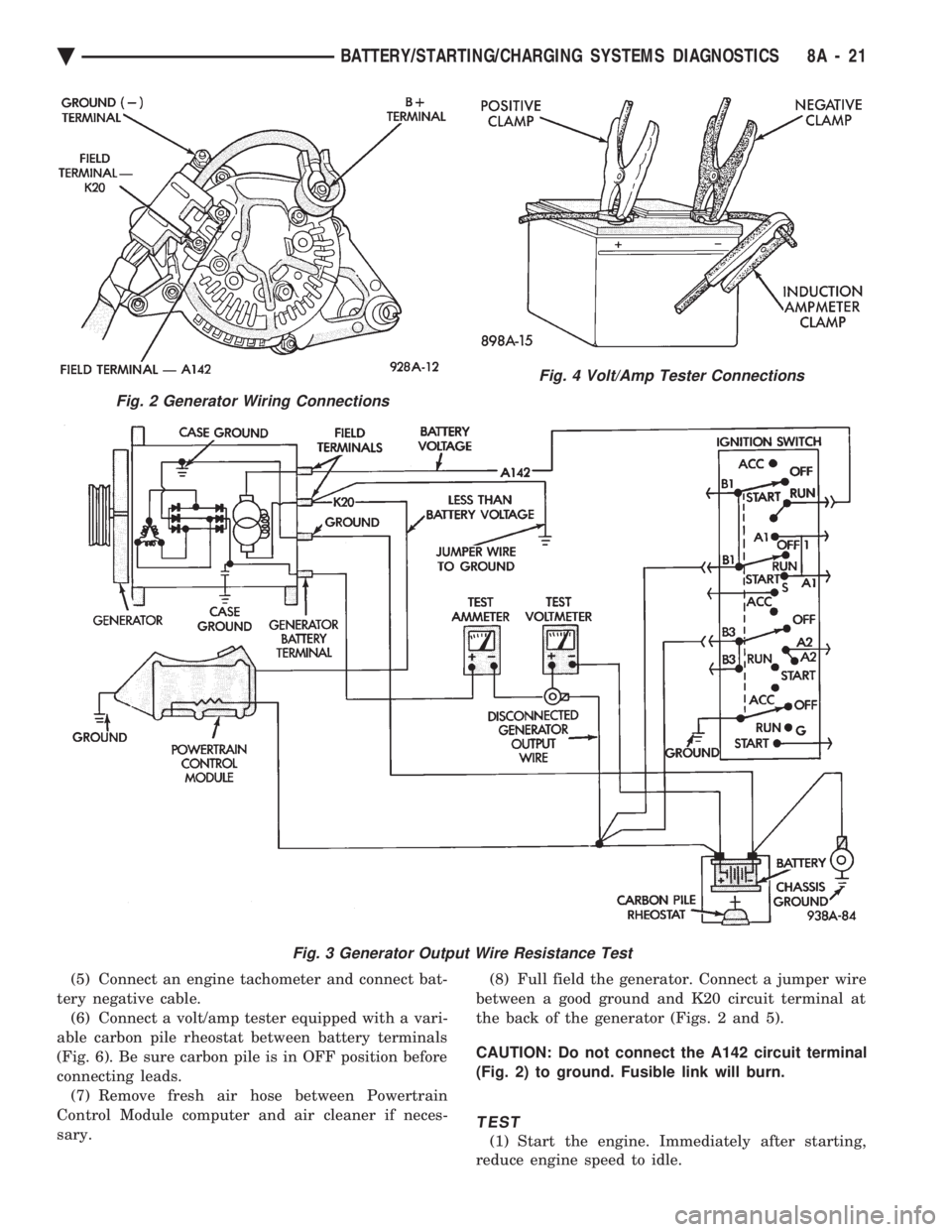
(5) Connect an engine tachometer and connect bat-
tery negative cable. (6) Connect a volt/amp tester equipped with a vari-
able carbon pile rheostat between battery terminals
(Fig. 6). Be sure carbon pile is in OFF position before
connecting leads. (7) Remove fresh air hose between Powertrain
Control Module computer and air cleaner if neces-
sary. (8) Full field the generator. Connect a jumper wire
between a good ground and K20 circuit terminal at
the back of the generator (Figs. 2 and 5).
CAUTION: Do not connect the A142 circuit terminal
(Fig. 2) to ground. Fusible link will burn.
TEST
(1) Start the engine. Immediately after starting,
reduce engine speed to idle.
Fig. 2 Generator Wiring Connections
Fig. 3 Generator Output Wire Resistance Test
Fig. 4 Volt/Amp Tester Connections
Ä BATTERY/STARTING/CHARGING SYSTEMS DIAGNOSTICS 8A - 21
Page 399 of 2438
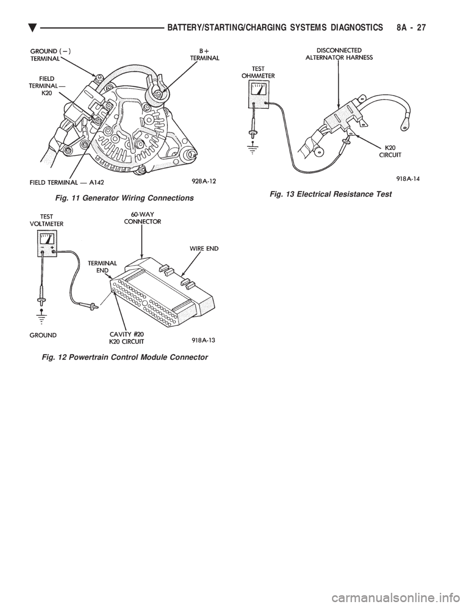
Fig. 11 Generator Wiring Connections
Fig. 12 Powertrain Control Module Connector
Fig. 13 Electrical Resistance Test
Ä BATTERY/STARTING/CHARGING SYSTEMS DIAGNOSTICS 8A - 27
Page 406 of 2438
STARTER INDEX
page page
General Information ........................ 4
Neutral Starter and Back-Up Switch ........... 8
Starter Component Replacement .............. 5
Starter Interlock Switch: Clutch Pedal Mounted/ Manual Transmission Only ................. 7 Starter Motor Replacement
.................. 4
Starting System ........................... 4
Supply Circuit and Control Circuit ............. 4
GENERAL INFORMATION
This section will cover Starter replacement and
service procedures only. For starter diagnostic proce-
dures, refer to Group 8A, Battery/Starting/Charging
Systems Diagnostics.
STARTING SYSTEM
The starting system has:
² Ignition switch
² Starter relay
² Neutral starting and back-up switch with auto-
matic transmissions
² Clutch pedal mounted starter interlock switch
with manual transmissions
² Wiring harness
² Battery
² Starter motor with an integral solenoid
BOSCH STARTERS
²A Bosch permanent magnet starter motor is avail-
able on 2.2L, 2.5L and 3.0L engines on all vehicles.
A planetary gear train transmits power between
starter motor and pinion shaft. The fields consist of
six permanent magnets.
NIPPONDENSO STARTERS
² A Nippondenso reduction gear-field coil starter
motor is available on 3.0L, 3.3L and 3.8L engines.
SUPPLY CIRCUIT AND CONTROL CIRCUIT
Both starter systems consist of two separate cir-
cuits:
² A high amperage supply to feed the starter motor.
² A low amperage circuit to control the starter sole-
noid. For additional information on starter motor supply
and control circuits, refer to Group 8A, Battery/Start-
ing/Charging Systems Diagnostics.
STARTER MOTOR REPLACEMENT
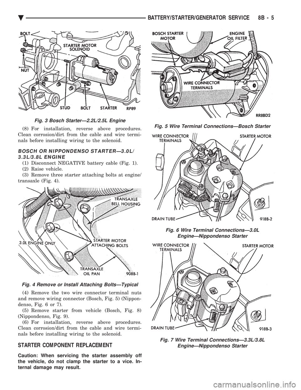
BOSCH STARTERÐ2.2L/2.5L ENGINE
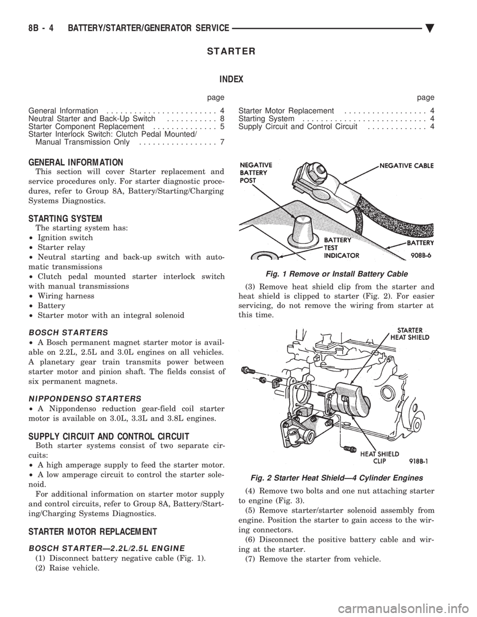
(1) Disconnect battery negative cable (Fig. 1).
(2) Raise vehicle. (3) Remove heat shield clip from the starter and
heat shield is clipped to starter (Fig. 2). For easier
servicing, do not remove the wiring from starter at
this time.
(4) Remove two bolts and one nut attaching starter
to engine (Fig. 3). (5) Remove starter/starter solenoid assembly from
engine. Position the starter to gain access to the wir-
ing connectors. (6) Disconnect the positive battery cable and wir-
ing at the starter. (7) Remove the starter from vehicle.
Fig. 1 Remove or Install Battery Cable
Fig. 2 Starter Heat ShieldÐ4 Cylinder Engines
8B - 4 BATTERY/STARTER/GENERATOR SERVICE Ä
Page 407 of 2438
(8) For installation, reverse above procedures.
Clean corrosion/dirt from the cable and wire termi-
nals before installing wiring to the solenoid.
BOSCH OR NIPPONDENSO STARTERÐ3.0L/ 3.3L/3.8L ENGINE
(1) Disconnect NEGATIVE battery cable (Fig. 1).
(2) Raise vehicle.
(3) Remove three starter attaching bolts at engine/
transaxle (Fig. 4).
(4) Remove the two wire connector terminal nuts
and remove wiring connector (Bosch, Fig. 5) (Nippon-
denso, Fig. 6 or 7). (5) Remove starter from vehicle (Bosch, Fig. 8)
(Nippondenso, Fig. 9). (6) For installation, reverse above procedures.
Clean corrosion/dirt from the cable and wire termi-
nals before installing wiring to the solenoid.
STARTER COMPONENT REPLACEMENT
Caution: When servicing the starter assembly off
the vehicle, do not clamp the starter to a vice. In-
ternal damage may result.
Fig. 3 Bosch StarterÐ2.2L/2.5L Engine
Fig. 4 Remove or Install Attaching BoltsÐTypical
Fig. 5 Wire Terminal ConnectionsÐBosch Starter
Fig. 6 Wire Terminal ConnectionsÐ3.0L EngineÐNippondenso Starter
Fig. 7 Wire Terminal ConnectionsÐ3.3L/3.8L EngineÐNippondenso Starter
Ä BATTERY/STARTER/GENERATOR SERVICE 8B - 5
Page 413 of 2438
(6) For installation, reverse above procedure.
Tighten all fasteners to the proper torque. Refer to
the Torque Specifications chart at the rear of this
group.
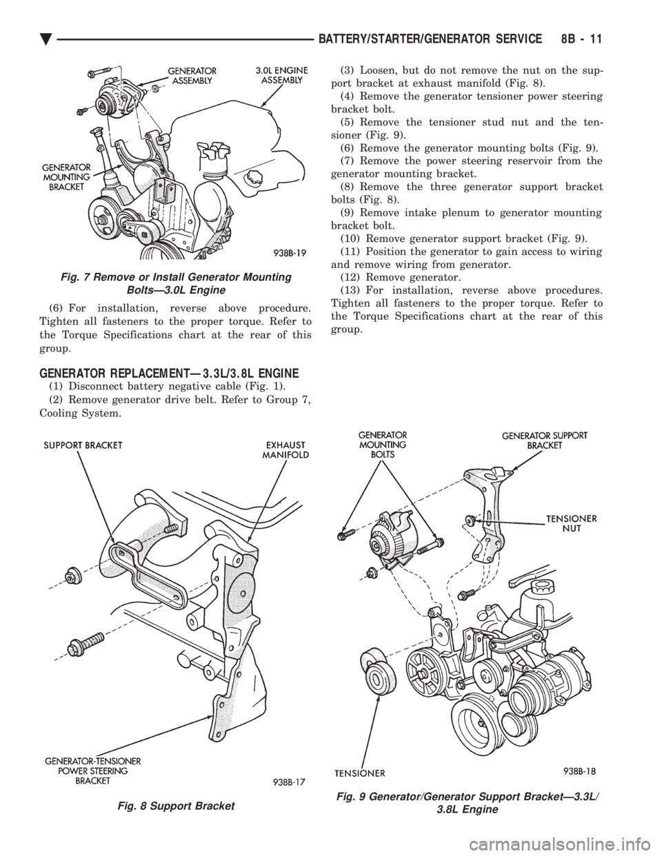
GENERATOR REPLACEMENTÐ3.3L/3.8L ENGINE
(1) Disconnect battery negative cable (Fig. 1).
(2) Remove generator drive belt. Refer to Group 7,
Cooling System. (3) Loosen, but do not remove the nut on the sup-
port bracket at exhaust manifold (Fig. 8). (4) Remove the generator tensioner power steering
bracket bolt. (5) Remove the tensioner stud nut and the ten-
sioner (Fig. 9). (6) Remove the generator mounting bolts (Fig. 9).
(7) Remove the power steering reservoir from the
generator mounting bracket. (8) Remove the three generator support bracket
bolts (Fig. 8). (9) Remove intake plenum to generator mounting
bracket bolt. (10) Remove generator support bracket (Fig. 9).
(11) Position the generator to gain access to wiring
and remove wiring from generator. (12) Remove generator.
(13) For installation, reverse above procedures.
Tighten all fasteners to the proper torque. Refer to
the Torque Specifications chart at the rear of this
group.
Fig. 7 Remove or Install Generator Mounting BoltsÐ3.0L Engine
Fig. 8 Support BracketFig. 9 Generator/Generator Support BracketÐ3.3L/ 3.8L Engine
Ä BATTERY/STARTER/GENERATOR SERVICE 8B - 11
Page 422 of 2438
COMPASS MODULE REPLACEMENT
(1) Remove overhead console.
(2) Using a small screwdriver, release the 2 snaps
at rear of compass module. (3) After releasing the 2 snaps, slide compass mod-
ule rearward until free of mounting bar. (4) For installation reverse above procedures.
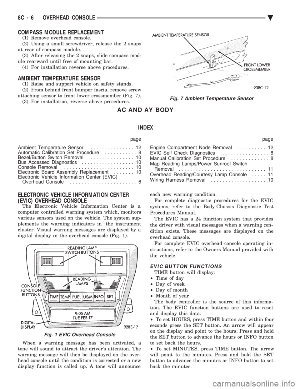
AMBIENT TEMPERATURE SENSOR
(1) Raise and support vehicle on safety stands.
(2) From behind front bumper fascia, remove screw
attaching sensor to front lower crossmember (Fig. 7). (3) For installation, reverse above procedures.
AC AND AY BODY
INDEX
page page
Ambient Temperature Sensor ............... 12
Automatic Calibration Set Procedure ........... 8
Bezel/Button Switch Removal ............... 10
Bus Accessed Diagnostics .................. 10
Console Removal ........................ 10
Electronic Board Assembly Replacement ....... 10
Electronic Vehicle Information Center (EVIC) Overhead Console ....................... 6 Engine Compartment Node Removal
.......... 12
EVIC Self Check Diagnostics ................ 8
Manual Calibration Set Procedure ............. 8
Map Reading Lamps/Power Sunroof Switch Removal .............................. 11
Overhead Reading/Courtesy Lamp Console ..... 11
Wiring Harness Removal ................... 10
ELECTRONIC VEHICLE INFORMATION CENTER
(EVIC) OVERHEAD CONSOLE
The Electronic Vehicle Information Center is a
computer controlled warning system which, monitors
various sensors used on the vehicle. The system sup-
plements the warning indicators in 8the instrument
cluster. Visual warning messages are displayed by a
digital display in the overhead console (Fig. 1).
When a warning message has been activated, a
tone will sound to attract the driver's attention. The
warning message will then be displayed on the over-
head console until the condition is corrected or a new
display function is called up. A tone will announce each new warning condition.
For complete diagnostic procedures for the EVIC
systems, refer to the Body-Chassis Diagnostic Test
Procedures Manual. The EVIC has a 24 function system that provides
the driver with visual messages when a warning con-
dition exists. These messages are displayed on the
overhead console. For complete EVIC overhead console operating in-
structions, refer to the Owners Manual provided with
the vehicle.
EVIC BUTTON FUNCTIONS
TIME button will display:
² Time of day
² Day of week
² Day of month
² Month of year
The body controller is the source of this informa-
tion. The EVIC function buttons are used to reset
and display this data.
² To set HOURS, press TIME button and within four
seconds press the SET button. An arrow will appear
on the display and point to the hours. Press and hold
the SET button to advance the hours or INFO button
to set back the hours.
² To set MINUTES, press TIME button. The arrow
will point to the minutes. Press and hold the SET
button to advance the minutes or INFO button to set
back the minutes.
Fig. 7 Ambient Temperature Sensor
Fig. 1 EVIC Overhead Console
8C - 6 OVERHEAD CONSOLE Ä
Page 426 of 2438
BUS ACCESSED DIAGNOSTICS
The following diagnostic test may be used to check
the integrity of the EVIC's internal connections and
operations. Refer to the Body Chassis Diagnostic Test
Procedure Manual for test procedures. MODULE RESET TEST, when the EVIC receives
this request from the DRB II, the EVIC will immedi-
ately enter into reset. DISPLAY TEST: The EVIC receives a request from
the DBR II, the EVIC will enter into a visual display
mode. Also checks the integrity of the display driver
to anode connections. The test shall consist of walk-
ing through the vertical and horizontal rows of an-
odes in the dot matrix display. SWITCH STATUS TEST, when the EVIC receives
this request from the DRB II, the EVIC will report
the open/closed status of each individual switch. FAULT BYTE TEST, when the EVIC receives this
request from the DRB II, the EVIC will report fault
status. Messages reported are:
² NO FAULT
² DISPLAY DRIVER FAULT
² EVIC MISSING MESSAGES
² POWER SUPPLY FAILURE
² FAULT IN RAM
² FAULT IN ROM
EVIC missing message implies that there may be a
system failure and/or the body controller is not pro-
viding EVIC with sufficient information. DISPLAY DRIVER FAULT, power supply failure
and fault in RAM/ROM implies that the EVIC is de-
fective.
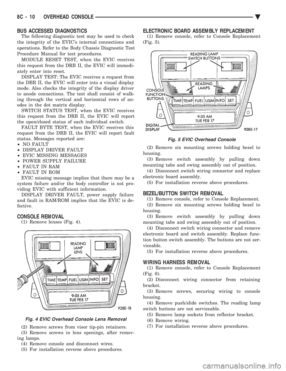
CONSOLE REMOVAL
(1) Remove lenses (Fig. 4).
(2) Remove screws from visor tip-pin retainers.
(3) Remove screws in lens openings, after remov-
ing lamps. (4) Remove console and disconnect wires.
(5) For installation reverse above procedures.
ELECTRONIC BOARD ASSEMBLY REPLACEMENT
(1) Remove console, refer to Console Replacement
(Fig. 5).
(2) Remove six mounting screws holding bezel to
housing. (3) Remove switch assembly by pulling down
mounting tabs and swing assembly out of position. (4) Disconnect switch wiring connector and replace
electronic board assembly. (5) For installation reverse above procedures.
BEZEL/BUTTON SWITCH REMOVAL
(1) Remove console, refer to Console Replacement.
(2) Remove six mounting screws holding bezel to
housing. (3) Remove switch assembly by pulling down
mounting tabs and swing assembly out of position. (4) Disconnect switch wiring connector and remove
electronic board and switch assembly. Replace func-
tion button switch assembly. The buttons are not ser-
viceable. (5) For installation reverse above procedures.
WIRING HARNESS REMOVAL
(1) Remove console, refer to Console Replacement
(Fig. 6). (2) Disconnect wiring connector from retaining
bracket. (3) Remove screws, securing wiring to console
housing. (4) Remove push/slide switches. The reading lamp
switch buttons are not serviceable. (5) Remove lamp sockets from reflector bracket.
(6) Remove wiring.
(7) For installation reverse above procedures.
Fig. 4 EVIC Overhead Console Lens Removal
Fig. 5 EVIC Overhead Console
8C - 10 OVERHEAD CONSOLE Ä
Page 427 of 2438
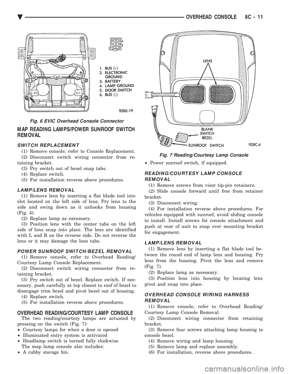
MAP READING LAMPS/POWER SUNROOF SWITCH
REMOVAL
SWITCH REPLACEMENT
(1) Remove console, refer to Console Replacement.
(2) Disconnect switch wiring connector from re-
taining bracket. (3) Pry switch out of bezel snap tabs.
(4) Replace switch.
(5) For installation reverse above procedures.
LAMP/LENS REMOVAL
(1) Remove lens by inserting a flat blade tool into
slot located on the left side of lens. Pry lens to the
side and swing down as it unhooks from housing
(Fig. 4). (2) Replace lamp as necessary.
(3) Position lens with the center tabs on the left
side of lens snap into place. The lens are identified
with L and R on the reverse side. Do not reverse the
lens or it may damage the lens tabs.
POWER SUNROOF SWITCH/BEZEL REMOVAL
(1) Remove console, refer to Overhead Reading/
Courtesy Lamp Console Replacement. (2) Disconnect switch wiring connector from re-
taining bracket. (3) Pry switch out of bezel. Replace switch. If nec-
essary, push carefully at top closest to roof of bezel to
disengage trim bezel and pivot bezel out of housing. (4) Replace switch.
(5) For installation reverse above procedures.
OVERHEAD READING/COURTESY LAMP CONSOLE
The two reading/courtesy lamps are actuated by
pressing on the switch (Fig. 7):
² Courtesy lamps for when a door is opened
² Illuminated entry system is activated
² Headlamp switch is turned fully clockwise
The map lamp console also includes:
² A cubby storage bin. ²
Power sunroof switch, if equipped.
READING/COURTESY LAMP CONSOLE
REMOVAL
(1) Remove screws from visor tip-pin retainers.
(2) Slide console forward until free from retainer
bracket. (3) Disconnect wiring.
(4) For installation reverse above procedures. For
vehicles equipped with sunroof, avoid sliding console
to install. Install screws for console attachment and
push at rear of unit to snap over mounting bracket
for engagement.
LAMP/LENS REMOVAL
(1) Remove lens by inserting a flat blade tool be-
tween the round end of lamp lens and housing. Pry
lens from the housing. Pivot the lens and remove
(Fig. 7). (2) Replace lamp as necessary.
(3) Position lens into housing by locating lens
pivot and snap into place.
OVERHEAD CONSOLE WIRING HARNESS REMOVAL
(1) Remove console, refer to Overhead Reading/
Courtesy Lamp Console Removal. (2) Disconnect wiring connector from retaining
bracket. (3) Remove four screws attaching lamp housing to
console bezel. (4) Remove wiring and lamp housing.
(5) Remove lamp and replace assembly.
(6) For installation, reverse above procedures.
Fig. 6 EVIC Overhead Console Connector
Fig. 7 Reading/Courtesy Lamp Console
Ä OVERHEAD CONSOLE 8C - 11
Page 429 of 2438
AG AND AJ BODIES INDEX
page page
Ambient Temperature Sensor Removal ......... 20
Compass Calibration ...................... 16
Compass Diagnostics ...................... 18
Compass Module Replacement .............. 20
Demagnetizing Procedure .................. 17
Electronic Vehicle Information Center (EVIC) ..... 13
Electronic Vehicle Information Center (EVIC) Removal .............................. 20 Engine Compartment Node (ECN)
............ 15
Engine Compartment Node Compass Calibration . 16
Engine Node Sensor Removal ............... 20
Map Reading Lamps ...................... 13
Overhead Console Replacement ............. 20
Thermometer and Compass ................. 16
Variance Procedure ....................... 17
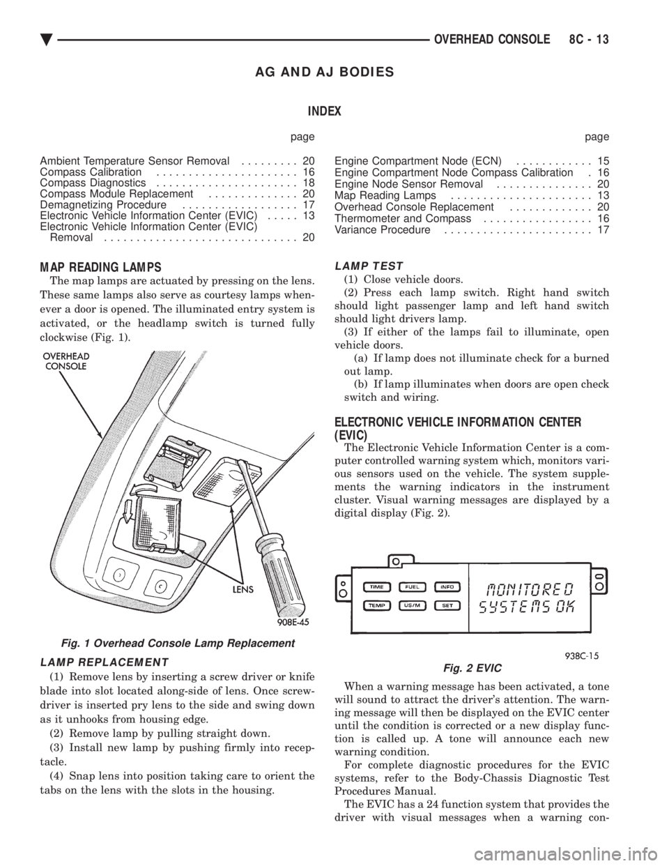
MAP READING LAMPS
The map lamps are actuated by pressing on the lens.
These same lamps also serve as courtesy lamps when-
ever a door is opened. The illuminated entry system is
activated, or the headlamp switch is turned fully
clockwise (Fig. 1).
LAMP REPLACEMENT
(1) Remove lens by inserting a screw driver or knife
blade into slot located along-side of lens. Once screw-
driver is inserted pry lens to the side and swing down
as it unhooks from housing edge. (2) Remove lamp by pulling straight down.
(3) Install new lamp by pushing firmly into recep-
tacle. (4) Snap lens into position taking care to orient the
tabs on the lens with the slots in the housing.
LAMP TEST
(1) Close vehicle doors.
(2) Press each lamp switch. Right hand switch
should light passenger lamp and left hand switch
should light drivers lamp. (3) If either of the lamps fail to illuminate, open
vehicle doors. (a) If lamp does not illuminate check for a burned
out lamp. (b) If lamp illuminates when doors are open check
switch and wiring.
ELECTRONIC VEHICLE INFORMATION CENTER
(EVIC)
The Electronic Vehicle Information Center is a com-
puter controlled warning system which, monitors vari-
ous sensors used on the vehicle. The system supple-
ments the warning indicators in the instrument
cluster. Visual warning messages are displayed by a
digital display (Fig. 2).
When a warning message has been activated, a tone
will sound to attract the driver's attention. The warn-
ing message will then be displayed on the EVIC center
until the condition is corrected or a new display func-
tion is called up. A tone will announce each new
warning condition. For complete diagnostic procedures for the EVIC
systems, refer to the Body-Chassis Diagnostic Test
Procedures Manual. The EVIC has a 24 function system that provides the
driver with visual messages when a warning con-
Fig. 1 Overhead Console Lamp Replacement
Fig. 2 EVIC
Ä OVERHEAD CONSOLE 8C - 13